Honeywell HE220 User manual

Category
Dehumidifiers
Type
User manual

This manual is also suitable for

® U.S. Registered Trademark
Copyright © 2002 Honeywell • •All Rights Reserved
INSTALLATION INSTRUCTIONS/OWNER’S GUIDE
69-1645EF
HE220, HE260 Humidifier and
Installation Kit
WELCOME
To the comfortable world of humidified air. When you use
your Honeywell humidifier, notice that your skin is not as
dry, and that your scratchy throat and irritated nasal
passages that aggravate allergies and asthma are
steadily improving.
You have also taken the first step in reducing the zapping
you create when you walk on your carpet and then touch
your TV, computer, metal door knob or your pet. Your
furniture and woodwork are also benefitting from the
difference that humidified air makes.
Congratulations! You have just made a great investment
in improving the comfort of your home.
APPLICATION
This kit contains your new Honeywell HE220 or HE260
Humidifier, H8908 Humidistat and all the accessories
required for installation.
INSTALLATION
Preparing for the Installation
Be sure to identify all the required (Table 1) accessories
(included) and make sure the appropriate tools are
available before beginning the installation.
Required Accessories (Included)
Required Tools
Tools required for installation include:
•Tin snip.
Screwdriver.
Adjustable or open-end wrench.
Drill, punch or awl.
•Level.
Table 1. Required Accessories.
Quantity Accessory
3 ft (0.93m) Bypass ducting including:
6 in. (155 mm) diameter flexible duct
Starter collar (flanged)
Plain collar
Summer shut-off damper
Connecting straps (2)
20 ft (6.2m) 18 gauge, two-strand thermostat wire
20 ft (6.2m) 1/4 in. (6.35 mm) OD feed water tubing
10 ft (3.1m) 1/2 in (12.7 mm) ID drain tubing
1 bag Connecting and mounting hardware:
Wire nuts (4)
No. 8 sheet metal screws (18)
Drain tube clamp
Feed tube mounting clamps (6)
Brass inserts (2)
Plastic compression rings (2)
1 Sail switch
1 H8908 Humidistat
1 bag Saddle Valve Assembly:
Saddle valve and top clamp (1)
Threaded bottom clamp (1)
Bolts (2)
Rubber gasket (1)
Brass insert (1)
Plastic bushing (1)
1 Plug-in transformer
HE220, HE260 HUMIDIFIER AND INSTALLATION KIT
69-1645EF 2
Determining Best Location for Humidifier
CAUTION
Temperature and Static Pressure Hazard.
Can cause property or equipment damage.
Locate humidifier where ambient temperature is
between 32°F (0°C) and 160°F (71°C).
Do not install humidifier where freezing
temperatures could occur.
Be sure supply plenum static pressure is no
greater than 0.4 in. wc and water pressure is no
greater than 124 psi.
Select a location for the humidifier on the supply
(warm air stream) plenum. See Fig. 1.
Select a location that cannot damage the air
conditioner A-coil during installation.
Do not locate the humidifier on the furnace body.
Allow adequate clearance in front of and above the
humidifier so you can easily remove the cover to
perform routine maintenance.
Mount the humidifier at least 3 in. (78 mm) above
the furnace body to allow adequate space for the
solenoid valve and drain line.
Mount the humidifier in a conditioned space to
prevent freezing.
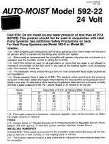
Fig. 1. Typical humidifier installation locations.
Selecting Water Supply Location
Use either hard or soft water in the humidifier and
either hot or cold water. The water flow rate, with the
humidifier running, is 3.5 gal/hr (13 liters/hr) to flush
the pad and provide moisture for evaporation.
Make sure that the 20 ft (6.2m) of feed water tubing
provided is adequate to connect the water supply
(saddle valve) with the humidifier solenoid valve.
Locating Closest Floor Drain
Select location with access to a floor drain to provide
drainage for air conditioner condensation and
humidifier drainage.
If you do not have a drain available, we recommend
that you install the Honeywell Whole House Drum or
Disk Humidifier. Make sure that the 10 ft (3.1m) of
drain tubing is adequate to reach from the humidifier
drain connection to the floor drain.
Selecting Location for Sail Switch
Select a location for the sail switch in the cold air
return duct where the sail is in the direct path of an
unrestricted air stream.
Sail switch detects when furnace fan is operating.
Select a location where the air duct is at least 12 in.
(305 mm) deep and 8 in. (203 mm) wide to allow
operation of the sail without affecting the smooth flow
of air in the duct.
Airflow at the location can be vertical (up or
down) or horizontal.
IMPORTANT
Mounting the S688 in warm air supply duct can
reduce the sail life.
Mount the switch at least 6 in. (152 mm) upstream
from an elbow or junction, and at least 15 in.
(381 mm) downstream from an elbow or junction.
Locate the switch on the opposite side of the duct
from the air entrance. (See Fig. 1-3 in S688
Installation Instructions.)
Selecting Location for Humidistat
Select a location for the humidistat on the return
plenum or on the wall in the living space.
Mounting on the return plenum is the easiest
installation for the control wiring circuit.
For return duct mounting, the humidistat should be
mounted upstream from the humidifier or bypass so that
it is properly sensing the relative humidity of the living
space. Locate the control at least 8 in. (203 mm)
upstream from the humidifier in the return air duct. (See
Fig. 2.)
Fig. 2. Selecting duct location for humidistat.
Locating Closest 120V Electrical Outlet
Select location with access to an outlet. If not
available, contact an electrician to have one installed.
Make sure that the humidifier cord is adequate to
reach from the humidifier to the outlet.
Make sure that the 20 ft (6.2m) of thermostat wire is
adequate to reach from the humidifier solenoid, to the
sail switch, to the humidistat.
M12808A
HORIZONTAL
DOWN
FLO
LOWBOY
RETURN
RETURN
RETURN
HIGHBOY
RETURN
ALTERNATE LOCATION
RETURN
AIR
RETURN
AIR
6 in. (152 mm)
MINIMUM
15 in. (381 mm)
MINIMUM
BEST
LOCATION
RETURN AIR DUCT
M12831
HE220, HE260 HUMIDIFIER AND INSTALLATION KIT
3 69-1645EF
Installing the Humidifier
WARNING
Hazardous Voltage
Can cause personal injury or equipment
damage.
Do not cut or drill into any air conditioning or
electrical accessory.
CAUTION
Sharp Edges Installation Hazard.
Can cause personal injury.
Wear gloves and safety glasses.
1. Turn off power to the air handing system at the cir-
cuit breaker.
2. Draw a level line on the plenum in the location
chosen for the humidifier. (Leveling assures opti-
mal humidifier performance.)
3. Locate the template (form number 69-1650
included in the box). For the HE220 model, cut
out the template along the dotted line.
4. Tape the template in position and trace around
the template.
5. Remove the template and carefully cut the rect-
angular opening.
6. Disassemble the humidifier; remove the cover and
take out the humidifier pad assembly. See Fig. 3.
Fig. 3. Disassembling humidifier.
7. Make sure the humidifier housing is level, then
position it in the opening so the plastic tabs are in
place on the lower sheet metal edge of the open-
ing. Use pliers, as necessary, to flatten cut edges.
See Fig. 4.
8. Secure the humidifier housing to the opening at the
top and bottom using sheet metal screws.
Fig. 4. Installing humidifier on duct.
9. Use the 6 in. (155 mm) starter collar as a template
to mark the opening for the bypass.
10. Carefully cut the opening for a 6 in. (155 mm)
starter collar. See Fig. 5. Use a drill, punch or awl
to start the cut in the middle of the circle. Cut in an
outward spiral to assist in controlling the cut.
Fig. 5. Cutting bypass opening.
11. Assemble the summer shutoff damper into the
starter collar. Verify that the damper rotates freely
between the open and closed positions. Make sure
the handle is accessible. Mark the damper Closed
position as Summer and the Open position as
Winter. See Fig. 6.
M12304A
WATER
FEED NOZZLE
FRAME
HUMIDIFIER
HOUSING
WATER
FEED TUBE
HUMIDIFIER
PAD ASSEMBLY
COVER
SIDEWALL
BY-PASS SIDEWALL
DUCT
LEVEL
SHEET METAL
SCREWS (4)
PLASTIC
TABS (2)
DRAIN TUBING
M20171
OPENING
TO AIR DUCT
STARTING
HOLE
6 IN. ROUND TEMPLATE
M20172
HE220, HE260 HUMIDIFIER AND INSTALLATION KIT
69-1645EF 4
Fig. 6. Installing the starter collar.
12. Remove liner to expose foam adhesive. Position
starter collar over opening.
13. Slide one end of the flexible ducting over the
starter collar and secure with one of the connecting
straps.
14. Insert the plain collar into the humidifier port and
secure with sheet metal screws. Connect the
flexible ducting over the collar and secure with a
connecting strap. See Fig. 7.
Fig. 7. Connecting bypass ducting.
15. Seal the duct connections with duct tape (not
included).
16. Reinstall the humidifier pad assembly in the humid-
ifier housing.
17. Hinge the cover in place and secure with the
thumbscrew located at the bottom of the cover.
Connecting the Plumbing
Use hot or cold water and either hard or softened water
in the humidifier.
1. Shut off the water.
CAUTION
Chemical Hazard.
Can cause personal injury or equipment
damage.
Do not use any line connected to an air
conditioner.
Do not use gas line.
2. Use the self-piercing saddle valve (included) to tap
into the water supply line at the location selected.
See Fig. 8. If tapping into galvanized pipe, drain
line and pre-drill 3/17 in. tap for saddle valve.
NOTE: The saddle valve is not designed to regulate
water flow. The valve is either open or closed.
IMPORTANT
To prevent debris from clogging the solenoid in-
line filter, be sure to install the saddle valve han-
dle pointing toward the ceiling.
Fig. 8. Installing the saddle valve.
3. Use 1/4 in. (6 mm) OD tubing and connect the sad-
dle valve to the inlet side of the solenoid valve on
the humidifier (see Fig. 9).
a. Place the brass compression nut over the
tubing.
b. Install brass insert into end of tubing.
c. Slide the plastic compression ring over the
tubing. (Discard copper compression ring pro-
vided with valve.)
NOTE: To prevent leaking, use plastic (Delrin) sleeve
rings with plastic tubing. Use copper sleeve
rings only with copper tubing.
d. Insert the tubing into the solenoid valve fitting
and support the valve while tightening the com-
pression nut.
NOTE: Do not over-tighten the compression nut. Mod-
erate tightness prevents leaking.
e. Repeat steps a. through d. for solenoid valve
fitting.
f. Secure tubing with clamps provided.
SUMMER
WINTER
M20173
M20785
PLAIN COLLAR
HUMIDIFIER PORT
M20175
SCREW DRIVER
WATER LINE
HE220, HE260 HUMIDIFIER AND INSTALLATION KIT
5 69-1645EF
Fig. 9. Installing feed tubing.
4. Connect a 1/2 in. (13 mm) drain tube to the humid-
ifier drain fitting and run to the floor drain (see Fig.
10).
a. Slide the drain clamp over the tubing.
b. Push the tubing over the drain nipple on the
humidifier.
c. Hand-tighten the clamp around the tubing to
secure the humidifier drain.
d. Fasten the drain tubing (can use duct tape)
along the route to prevent movement and
ensure downward slope for correct drainage.
NOTE: Cut tubing to correct length so the tubing termi-
nates at the drain.
Fig. 10. Installing the drain tubing.
Installing the Sail Switch
Adapting Switch to Air Flow Direction
The S688A Sail Switch has two counterbalancing springs
in place as shown in Fig 11. These springs offset the
effect of gravity for air flow direction.
IMPORTANT
Do not use the sail switch with both springs
attached. Be sure to select air flow direction and
remove spring(s) not required for installation.
Fig. 11. Adapting sail switch to air flow direction or
mounting position.
Vertical downward air flow: Leave the spring in
place that is attached to the bracket marked Down.
Remove the spring that is attached to the bracket
marked Up.
Vertical upward air flow: Leave the spring in place
that is attached to the bracket marked Up. Remove
the spring that is attached to the bracket marked
Down.
Horizontal air flow: Remove both springs.
1. Mount the template (provided with the sail switch)
at the desired location.
NOTE: Be sure the arrow (indicating air flow) points in
the correct direction.
a. For horizontal mounting, level the long dimen-
sion shown on the template.
b. For vertical mounting, plumb the long dimen-
sion.
2. Cut the hole (indicated on the template) in the duct-
work.
3. Center punch the screw holes indicated and drill
out with a 1/8 in. (13 mm) drill.
4. Attach the sail to the switch as shown in Fig 12.
M20176
BRASS COMPRESSION NUT
PLASTIC
COMPRESSION RING
BRASS INSERT
M20177
UP
M3014
HE220, HE260 HUMIDIFIER AND INSTALLATION KIT
69-1645EF 6
Fig. 12. Attaching sail to switch.
5. Press together the sides of the wire loop. Insert the
sail into the duct. (When in the Off position, the sail
should point into the direction of airflow as shown
in Fig.13.)
Fig. 13. Inserting sail switch in direction of airflow.
6. Secure the switch by using the sheet metal screws
provided.
7. After wiring, snap on the cover.
Installing the Humidistat
Installing on Mounting Duct
1. Apply the template to the duct location chosen
for the humidistat. Make sure the template is
level before drilling the holes.
2. Refer to the template (provided with the H8908
Humidistat Installation Instructions) to drill the
control assembly opening and mounting holes
for the H8908.
3. Remove the H8908 case from the base.
4. Position the foam gasket on the H8908 base.
5. Position the base on the duct with the arrow up.
6. Secure the base to the duct using the four
1 in. (25 mm) mounting screws provided with humi-
distat.
7. Connect the low-voltage wires to the leads and
replace the H8908 case. See Fig. 14.
NOTE: For wall mounting instructions, see the H8908
Installation Instructions.
Fig. 14. Humidistat base and rear view.
WIRING
CAUTION
Hazardous Voltage.
Can cause personal injury or equipment
damage.
Disconnect power supply before installing or
servicing equipment.
IMPORTANT
All wiring must comply with applicable local
code, ordinances and regulations.
Wire the humidifier solenoid valve, sail switch, humidistat
and transformer. See Fig. 15.
Fig. 15. Wiring the controls.
– LOOSEN SETSCREW
– INSERT SAIL
– TIGHTEN SETSCREW
SAIL
M20181
M20178
AIRFLOW
M20179
WIRE SLOT
HUMIDISTAT WIRES
HUMIDISTAT BASE REAR OF HUMIDISTAT
Humidity Control
Régulateur d'humidité
-20
¡F
-10 ¡F
0 ¡F
+10 ¡F
+20 ¡F
Over 20 ¡F
15%
20%
25%
30%
35%
40%
HUMIDITY
SETTING
OUT
DOOR
TEMPERATURE
-30
¡C
-25 ¡C
-20 ¡C
-10 ¡C
-5 ¡C
Over 0 ¡C
M20180
TRANSFORMER
BLACK
BLACK
BLACK
WHITE
WHITE
HUMIDIFIER
SOLENOID
VALVE
HUMIDISTAT
SAIL
SWITCH
HE220, HE260 HUMIDIFIER AND INSTALLATION KIT
7 69-1645EF
1. Run the two-strand thermostat wire from the
humidifier to the humidistat, and from the humidis-
tat to the sail switch.
2. Cut lengths of thermostat wire to reach between
components, leaving adequate wire at both ends
for connections.
NOTE: Humidistat and sail switch can be wired in any
order.
3. At the humidifier, connect the black and white con-
ductors to the two yellow humidifier wires. (The red
wires from the humidifier are not used.)
4. At the humidistat, connect both black conductors to
the two humidistat terminals. Use a wire nut to con-
nect together the two white conductors.
5. At the sail switch, connect the black and white con-
ductors to the Com and NO sail switch terminals
(NC terminal is not used).
TESTING HUMIDIFIER OPERATION
Checklist
Humidifier is level.
Control wiring was reviewed using circuit diagram.
Humidifier is plugged in.
Feed line has no kinks.
Drain line slopes continuously down and ends at floor
drain.
Water hose inside humidifier is connected to
PerfectFlow™ water distribution tray.
After installation use the following steps to check the
humidifier operation:
1. Turn on the power and the water supply
2. Turn the H8908 Humidistat to On and turn on the
heat by setting the thermostat to 10ºF (6ºC) above
room temperature.
IMPORTANT
The furnace blower must be on to activate the
humidifier.
3. Make sure that water is flowing out of the drain
hose. If water does not flow, see Troubleshooting
Your Humidifier section.
4. Check for leaks.
5. Reset the thermostat and H8908 Humidistat to a
comfortable setting for automatic operation.
OPERATION
How Your Humidifier Works
Your Honeywell humidifier uses the principle that vapor
(evaporated water) is created when warm air blows over
a water-soaked area. As the vapor circulates, the relative
humidity rises.
Your humidity control monitors the relative humidity and
activates the humidifier accordingly. The humidifier has a
water supply that dispenses water evenly over a
humidifier pad. The warm dry air, from the furnace,
passes over the humidifier pad and picks up the moist air
to circulate it throughout your home.
Humidified air feels warmer and more comfortable so you
may be able to lower your thermostat heating setpoint,
which saves money on your heating fuel bills. The end
result is that your humidifier gives you a comfortable
environment that is also energy efficient.
Controlling Your Humidity Settings
Your H8908 Humidistat controls your humidifier.
Choose the humidity control setting using the
combination of relative humidity/outdoor temperature
setting scale on your humidity control dial.
Match the dial setting to the outdoor temperature to
optimize the humidity level while reducing the
moisture condensation on your windows. See Table 2
to adjust the humidity control to the recommended
setting.
NOTE: As the outside temperature drops, a lower
humidity setting is recommended to accommo-
date dewpoint effects. These settings should
reduce the accumulation of moisture and ice on
windows and other areas of the home.
Adjust the humidity control setting to adjust for indoor
activities such as cooking, showering and clothes
drying, which can cause excessive levels of humidity
that can accumulate moisture on your windows.
NOTE: If these activities persist for more than a few
hours, set the humidity control to the lowest set-
ting to turn off the humidifier. If the condition
does not improve, ventilate your home to
remove the moisture.
Table 2. Setting Your Humidistat.
When Outside
Temperature is:
Use This Control
Setting:
-20°F (-29°C) 15
-10°F (-23°C) 20
0°F (-18°C) 25
+10°F (-12°C) 30
+20°F (-7°C) 35
Above 20°F (-7°C) 40
HE220, HE260 HUMIDIFIER AND INSTALLATION KIT
69-1645EF 8
MAINTAINING YOUR HUMIDIFIER
A regular maintenance program prolongs the life of your
humidifier and makes your home more comfortable. The
frequency of cleaning depends on the condition of your
water.
You can use either hard or soft water in your humidifier,
but hard water mineral deposits are more difficult to clean
than soft water deposits.
Use the following procedure to clean your Honeywell
humidifier.
WARNING
Serious Personal Injury Hazard.
Can cause electrical shock and injury from
moving parts.
Disconnect power and shut off water supply
before removing cover.
IMPORTANT
Never oil any part of the humidifier.
Every 1 to 3 Months (Depending on Water
Quality)
1. Disconnect the power and turn off the humidifier
water supply.
2. Remove the humidifier cover. See Fig. 16.
3. Remove the humidifier pad assembly from the
humidifier by grasping the top of the tray and pull-
ing it toward you.
4. Pull one side of the humidifier pad assembly frame
toward you and remove the tray from the frame.
5. Gently pinch the water nozzle catches inward until
you can lift the water nozzle off the tray.
6. Slide the humidifier pad out of the frame.
7. Carefully remove any mineral deposits from the
tray and frame. Be sure the frame drain hole has
nothing blocking it.
8. Disconnect the drain hose from the drain fitting on
the bottom of the humidifier housing.
9. Clean the drain fitting, if necessary.
10. Bend the drain hose to loosen any mineral depos-
its.
11. Flush the drain hose with pressurized water (a run-
ning tap) to clean the hose.
12. Reattach the drain hose to the drain fitting.
13. Slide the humidifier pad back into the frame.
14. Snap the water nozzle back on the tray.
15. Reattach the tray to the frame.
16. Place the humidifier pad assembly in the humidifier
housing and press until the assembly is completely
seated. Be careful not to pinch or kink the water
feed tube.
17. Replace the humidifier cover.
18. Verify the humidifier operation by following the
steps in the Checking Your Humidifier for Correct
Operation section.
End of Humidification Season
Clean the humidifier and shut it off at the end of the
heating season.
Use Every 1 to 3 Months section steps to shut down
for the season.
IMPORTANT
Be sure the humidifier power is off.
Vacation
When leaving on vacation, turn off the humidifier
water supply and your humidistat.
When you return, turn on the humidifier water supply
and reset your humidistat.
Fig. 16. Cleaning your humidifier.
CHECKING YOUR HUMIDIFIER FOR
CORRECT OPERATION
After winter startup or servicing, use the following steps
to check your humidifier operation:
1. Turn on the humidifier power and water supply.
2. Turn the humidistat to its highest setting and set
the thermostat to 10°F (6°C) above the room tem-
perature.
3. Observe that water is flowing out of the drain hose.
NOTE: The furnace blower must be running to activate
the humidifier.
4. Reset the thermostat and humidistat to a comfort-
able setting for automatic operation.
M12327A
PerfectFlo WATER
DISTRIBUTION TRAY
HUMIDIFIER PAD ASSEMBLY
WATER FEED NOZZLE
HUMIDIFIER HOUSING
SIDEWALL
BYPASS SIDEWALL
COVER
WATER FEED TUBE
HE220, HE260 HUMIDIFIER AND INSTALLATION KIT
9 69-1645EF
TROUBLESHOOTING YOUR HUMIDIFIER
Table 3. Troubleshooting Humidifier.
Problem What to look for What to do
Water leakage Leaking joints. Shut off water.
Tighten connections.
Brass tubing inserts Verify that brass tubing inserts are used.
Saddle valve leaking. Verify rubber pad is installed on saddle valve.
No water to drain. Electrical Verify control circuit wiring.
Check all connections.
Humidistat Turn humidistat up and down and listen for contact
to click.
Humidifier power Verify that outlet has power.
Sail switch Remove sail cover; turn on furnace fan and listen
for faint click.
Verify that sail can move freely in duct; check sail
switch instructions to trim sail, if necessary.
Solenoid After verifying other wiring components, turn on
furnace fan, turn humidistat up and down, and listen
for solenoid to click.
Plumbing Verify plumbing connections.
Check for kinks.
Saddle valve Verify that needle pierces water line and then backs
out needle to open valve.
Humidifier Remove cover and verify that water flows into
distribution tray.
Drain tubing Verify no obstructions.
Air leakage Check duct joints Seal with duct tape.
Low humidity Furnace blower not operating. Reset circuit breaker or check for blown fuse.
Check that the furnace power is on.
Check all external wiring connections.
Check the humidity control setting.
Call a professional heating contractor.
Rapid air changes. Drafts (cold
air is dry and is an added load
to the humidifier).
Keep doors and windows closed.
Close fireplace damper when not in use.
Keep exhaust fan running time to a minimum.
Seal around doors and windows.
High humidity Condensation on walls. Turn off humidity control and water until
condensation is completely evaporated.
Heavy condensation on
windows.
Turn humidity control down low enough to
eliminate condensation caused by moisture from
bathing, mopping, cooking, etc. If moisture
persists, more ventilation is needed.
HE220, HE260 HUMIDIFIER AND INSTALLATION KIT
69-1645EF 10
LIMITED ONE-YEAR WARRANTY
Honeywell warrants this product, excluding humidifier pad, to be free from defects in the workmanship or
materials, under normal use and service, for a period of one (1) year from the date of purchase by the
consumer. If, at any time during the warranty period, the product is defective or malfunctions, Honeywell
shall repair or replace it (at Honeywell’s option) within a reasonable period of time.
If the product is defective, return it, with a bill of sale or other dated proof of purchase, to the retailer where
you purchased it.
This warranty does not cover removal or reinstallation costs. This warranty shall not apply if it is shown by
Honeywell that the defect or malfunction was caused by damage which occurred while the product was in
the possession of a consumer.
Honeywell’s sole responsibility shall be to repair or replace the product within the terms stated above.
HONEYWELL SHALL NOT BE LIABLE FOR ANY LOSS OR DAMAGE OF ANY KIND, INCLUDING ANY
INCIDENTAL OR CONSEQUENTIAL DAMAGES RESULTING, DIRECTLY OR INDIRECTLY, FROM ANY
BREACH OF ANY WARRANTY, EXPRESS OR IMPLIED, OR ANY OTHER FAILURE OF THIS
PRODUCT. Some states do not allow the exclusion or limitation of incidental or consequential damages, so
this limitation may not apply to you.
THIS WARRANTY IS THE ONLY EXPRESS WARRANTY HONEYWELL MAKES ON THIS PRODUCT.
THE DURATION OF ANY IMPLIED WARRANTIES, INCLUDING THE WARRANTIES OF
MERCHANTABILITY AND FITNESS FOR A PARTICULAR PURPOSE, IS HEREBY LIMITED TO THE
ONE YEAR DURATION OF THIS WARRANTY. Some states do not allow limitations on how long an
implied warranty lasts, so the above limitation may not apply to you.
This warranty gives you specific legal rights, and you may have other rights which vary from state to state.
If you have any questions concerning this warranty, please write to Honeywell Customer Care, 1885
Douglas Drive, Minneapolis, MN55422. In Canada, write Retail Products ON15-02H, Honeywell Limited/
Honeywell Limitée, 35 Dynamic Drive, Scarborough, Ontario M1V 4Z9.
69-1645EF G.H. 9-02 www.honeywell.com/yourhome
HE220, HE260 HUMIDIFIER AND INSTALLATION KIT
Printed in U.S.A. on recycled
paper containing at least 10%
post-consumer paper fibers.
Automation and Control Solutions
Honeywell Honeywell Limited-Honeywell Limitée
1985 Douglas Drive North 35 Dynamic Drive
Golden Valley, MN 55422 Scarborough, Ontario
M1V 4Z9
Imprimé aux États-Unis sur du papier
recyclé contenant au moins 10 %
de fibres post-consommation.
69-1645EF G.H. 9-02 www.honeywell.com/yourhome
HUMIDIFICATEURS HE220 ET HE260 ET TROUSSE D'INSTALLATION
Solutions de régulation et d'automatisation
Honeywell Honeywell Limited-Honeywell Limitée
1985 Douglas Drive North 35, Dynamic Drive
Golden Valley, MN 55422 Scarborough (Ontario)
M1V 4Z9
  • Page 1 1
  • Page 2 2
  • Page 3 3
  • Page 4 4
  • Page 5 5
  • Page 6 6
  • Page 7 7
  • Page 8 8
  • Page 9 9
  • Page 10 10
  • Page 11 11
  • Page 12 12
  • Page 13 13
  • Page 14 14
  • Page 15 15
  • Page 16 16
  • Page 17 17
  • Page 18 18
  • Page 19 19
  • Page 20 20
  • Page 21 21
  • Page 22 22
  • Page 23 23
  • Page 24 24

Honeywell HE220 User manual

Category
Dehumidifiers
Type
User manual
This manual is also suitable for

Ask a question and I''ll find the answer in the document

Finding information in a document is now easier with AI

in other languages