
COM-2(PC)F
RS-232C (2ch) Serial I/O Board
User’s Guide

COM-2(PC)F i
Copyright
Copyright 1996 CONTEC Co., LTD. ALL RIGHTS RESERVED
No part of this document may be copied or reproduced in any form
by any means without prior written consent of CONTEC Co., LTD.
CONTEC Co., LTD. makes no commitment to update or keep
current the information contained in this document. The
information in this document is subject to change without notice.
All relevant issues have been considered in the preparation of this
document. Should you notice an omission or any questionable
item in this document, please feel free to notify CONTEC Co.,
LTD.
Regardless of the foregoing statement, CONTEC assumes no
responsibility for any errors that may appear in this document nor
for results obtained by the user as a result of using this product.
Trademarks
MS, Microsoft, MS-DOS, Windows and Windows NT are
trademarks of Microsoft Corporation. Other brand and product
names are trademarks of their respective holder.

COM-2(PC)Fii
Product Configuration
- COM-2(PC)F Board…1
- Sample Program Diskette (3.5inch/1.44MB)…1
- User's Guide (This Booklet)…1
Unpacking:
This board is specially packed in an anti-static bag to prevent
damage in shipping.
Check the contents to make sure that you have everything listed
above. If you do not have all the items, contact your distributor
or CONTEC group office where you purchased.
Note!
Do not remove the board from its protective packaging until the
computer case is open and ready for installation. Electrical static
can cause damage to electrical components.

COM-2(PC)F iii
Table of Contents
Copyright............................................................................i
Trademarks ........................................................................i
Product Configuration ..................................................... ii
1. Introduction .............................................................1
About the COM-2(PC)F Board.....................................1
Support Software of Option..........................................1
Features.........................................................................1
Limited Three-Year Warranty......................................2
How to Obtain Service..................................................2
Liability.........................................................................2
About the Manual.........................................................3
2. How to Use the Board ...............................................5
Compatible Mode and Enhanced Mode ...........................5
Compatible Mode..........................................................5
Enhanced Mode.............................................................5
Operating under Windows Me/98.....................................6
Procedure.......................................................................6
Operating under Windows 95.........................................10
Procedure.....................................................................10
Operating under Windows 2000.....................................14
Procedure.....................................................................14
Operating under Windows NT .......................................18
Procedure.....................................................................18
Operating under Windows 3.1........................................19
Procedure.....................................................................19
Operating under MS-DOS..............................................20
Procedure.....................................................................20
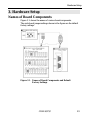
3. Hardware Setup ..................................................... 23
Names of Board Components.........................................23
I/O Address Setting.........................................................24
Setting Procedure .......................................................25
Interrupt Level Setting...................................................26
Setting Procedure .......................................................26

COM-2(PC)Fiv
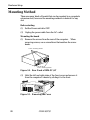
Mounting Method............................................................28
Connecting the External Devices...................................31
Connecting the Cable......................................................32
4. System Reference.................................................... 33
Specifications...................................................................33
Circuitry Diagrams.........................................................34
Block Diagram.................................................................34
5. Troubleshooting...................................................... 35
QUESTIONS:..................................................................35
Is the pilot light on?....................................................35
Did the system boot up? .............................................35
Does your program work?...........................................35
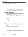
Does the sample program work?................................36
Is the input data accurate?.........................................36
Still have a probrem?..................................................36
6. Appendix................................................................ 39
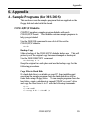
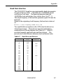
A. Sample Programs (for MS-DOS)................................39
COM-2(PC)F Diskette ................................................39
Sample Programs........................................................40
Switch and Jumper Settings......................................42
Cable Connection........................................................44
B. Notes on Developing Driver Software.......................56
Internal Registers.......................................................56
Baud Rate Selection....................................................57
LSI Recovery Time......................................................58
Various Aspects of Interrupt Handling in Enhanced
Mode and Compatible Mode.......................................60
C. The Details on NS16550 ............................................62
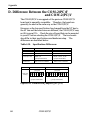
D. Difference Between the COM-2(PC)F
and COM-2(PC)V.......................................................64
7. Index ..................................................................... 65

COM-2(PC)F v
List of Figures
Figure 3.1. Names of Board Components and Default Factory
Settings..................................................................... 23
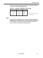
Figure 3.2. I/O Address DIP Switch............................................ 25
Figure 3.3. Interrupt Level Settings............................................. 26
Figure 3.4. Rear Panel of IBM-PC/AT ......................................... 28
Figure 3.5. Removing the Cover.................................................. 28
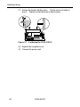
Figure 3.6. Expansion Slot Cover................................................ 29
Figure 3.7. Anchoring the COM-2(PC)F..................................... 30
Figure 3.8. Interface Connectors (CN1 and CN2)........................ 31
Figure 3.9. CN1 and CN2 Pin Assignments................................ 31
Figure 3.10.Example Connection to a Modem ............................. 32
Figure 3.11.Example Connection to a PC..................................... 32
Figure 3.12.Example Connection to a Device............................... 32
Figure 4.1. Circuitry Diagrams.................................................... 34
Figure 4.2. COM-2(PC)F Block Diagram.................................... 34
Figure 6.1. Floppy Disk Files...................................................... 40
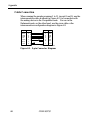
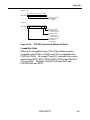
Figure 6.2. 9-pin Connector Diagram.......................................... 44
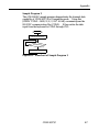
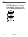
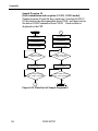
Figure 6.3. Flowchart of Sample Program 1................................ 45
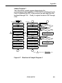
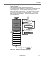
Figure 6.4. Flowchart of Sample Program 2................................ 46
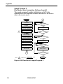
Figure 6.5. Flowchart of Sample Program 3................................ 47
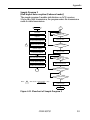
Figure 6.6. Flowchart of Sample Program 4................................ 48
Figure 6.7. Flowchart of Sample Program 5................................ 49
Figure 6.8. Flowchart of Sample Program 6................................ 50
Figure 6.9. Flowchart of Sample Program 7................................ 51
Figure 6.10.Flowchart of Sample Program 8................................ 52

COM-2(PC)Fvi
Figure 6.11.Flowchart of Sample Program 9................................ 53
Figure 6.12.Flowchart of Sample Program10............................... 54
Figure 6.13.Flowchart of Sample Program 11 .............................. 55
Figure 6.14. IVR Bit Function in Enhanced Mode........................ 61
Figure 6.15.Difference in Jumpers (JP1~JP3)............................... 64

COM-2(PC)F vii
List of Tables
Table 2.1. COM Port Support for Various Programming
Languages................................................................. 21
Table 3.1. I/O Address Settings................................................. 25
Table 3.2. Example Compatible Mode Settings......................... 27
Table 4.1. Specifications............................................................ 33
Table 6.1. Data Format.............................................................. 40
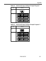
Table 6.2. Switch and Jumper Settings of Sample Program 1, 2,
and 5......................................................................... 42
Table 6.3. Switch and Jumper Settings of Sample Program 3, 4, 6,
and 10....................................................................... 42
Table 6.4. Switch and Jumper Settings of Sample Program 7 .... 43
Table 6.5. Switch and Jumper Settings of Sample Program 11... 43
Table 6.6. Function Selection through Internal Registers........... 56
Table 6.7. Baud Rate and Divisors............................................. 57
Table 6.8. Number of Times the IN Instruction Must be Executed
for the 2EFh Port after Accessing the LSI................. 58
Table 6.9. NS16550's Register (Short from National
Semiconductor's data book) < 1 / 2 > .................... 62
Table 6.9. NS16550's Register (Short from National
Semiconductor's data book) < 2 / 2 > .................... 63
Table 6.10. Specifications Differences....................................... 64

COM-2(PC)Fviii

Introduction
COM-2(PC)F 1
1. Introduction
About the COM-2(PC)F Board
The COM-2(PC)F is an IBM PC/AT ISA-Bus add-on interface
board for multi-channel RS-232C asynchronous communications.
It features two serial communication ports and a programmable
communication rate ranging from 50 to 115,200 bps for
communication or modem control.
Support Software of Option
- For Windows API-PAC(W32)
- For Windows 3.1 API-SIO(PC)WIN
- For MS-DOS SUPPORT-PAC(PC)103
Features
- 2-channel asynchronous communication
- Supports RS-232C protocol
- Programmable communication rate from 50 to 115,200 bits per
second
- Two operational modes : Enhanced and Compatible
(COM1, COM2, COM3, and COM4)
For more information, see System Reference.

Introduction
COM-2(PC)F2
Limited Three-Year Warranty
CONTEC Interface boards are warranted by CONTEC Co., LTD to
be free from defects in material and workmanship for up to three
years from the date of purchase by the original purchaser.
Repair will be free of charge only when this device is returned
freight prepaid with a copy of the original invoice and a Return
Merchandise Authorization to the distributor or the CONTEC group
office, from which it was purchased.
This warranty is not applicable for scratches or normal wear, but
only for the electronic circuitry and original boards. The warranty
is not applicable if the device has been tampered with or damaged
through abuse, mistreatment, neglect, or unreasonable use, or if the
original invoice is not included, in which case repairs will be
considered beyond the warranty policy.
How to Obtain Service
For replacement or repair, return the device freight prepaid, with a
copy of the original invoice. Please obtain a Return Merchandise
Authorization Number (RMA) from the CONTEC group office
where you purchased before returning any product.
*No product will be accepted by CONTEC group without the
RMA number.
Liability
The obligation of the warrantor is solely to repair or replace the product.
In no event will the warrantor be liable for any incidental or
consequential damages due to such defect or consequences that arise
from inexperienced usage, misuse, or malfunction of this device.

Introduction
COM-2(PC)F 3
About the Manual
This manual consists of the following chapters :
Chapter 1 Introduction
Chapter 2 How to Use the Board
Chapter 3 Hardware Setup
Chapter 4 I/O Ports and Registers
Chapter 5 System Reference
Chapter 6 Troubleshooting
Chapter 7 Index

Introduction
COM-2(PC)F4

How to Use the Board
COM-2(PC)F 5
2. How to Use the Board
Compatible Mode and Enhanced Mode
The COM-2(PC)F supports Compatible mode and Enhanced mode.
In Compatible mode, the board channels operate as standard PC
serial ports. In Enhanced mode, the board operates under
CONTEC's proprietary control procedures. Give full
consideration to the features of each mode when selecting which
mode to use in your system.
Compatible Mode
The two channels of the COM-2(PC)F can be used as standard PC
serial ports. Channel CN1 of the COM-2(PC)F can be assigned as
COM1 or COM3, and channel CN2 can be assigned as COM2 or
COM4.
In Compatible mode, each channel uses one interrupt level.
Therefore, your PC must have at least two interrupt levels available.
The COM-2(PC)F uses the I/O addresses assigned to the standard
serial ports.
As the COM-2(PC)F channels operate as standard serial ports, the
board can be accessed using either the CONTEC driver software
(purchased separately) or some other driver software that supports
standard serial ports.
Enhanced Mode
The COM-2(PC)F operates under CONTEC's proprietary control
procedures.
In Enhanced mode, a single interrupt level is used to control both
channels. Therefore, the board can be used even if your PC has
only one free interrupt level available. The I/O address used is
specified by CONTEC.
As the board operates under CONTEC's proprietary control
procedures, you must use the CONTEC driver software (purchased
separately) or develop your own driver software. Programming
for Enhanced mode is different to programming for Compatible
mode.

How to Use the Board
COM-2(PC)F6
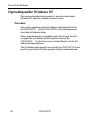
Operating under Windows Me/98
This section describes the procedure for using the board under
Windows Me/98 and lists a number of points to note.
Procedure
When using the board under Windows Me/98, the OS must be set to
recognize the I/O address and interrupt level used by the
COM-2(PC)F. In Windows Me/98, this is called hardware
installation. Use the following installation procedure.
Check the Current Settings
First, check the current settings. Check which interrupt levels are
available. If using in Compatible mode, also check which COM
ports (COM1 to COM4) are already set. The COM-2(PC)F cannot
be assigned to a COM port that is already set. The procedure for
checking is as follows.
- Check the interrupt level
1. Select [System] from [Control Panel] and open [Device
Manager].
2. Select the [Computer] folder and click [Properties].
3. Display the [Interrupt request(IRQ)] list and check which
interrupt levels are available.
- Check the ports
1. Select [System] from [Control Panel] and open [Device
Manager].
2. Double click on the [Ports (COM & LPT)], [Infrared], [Modem]
folder and check which ports are already set.

How to Use the Board
COM-2(PC)F 7
Compatible Mode Installation Procedure 1
1. Set the operation mode (I/O address) and interrupt level for the
COM-2(PC)F. Set the COM-2(PC)F switch and jumpers as
described in Hardware Setup. Set an interrupt level that is not
currently used by the computer.
2. Insert the COM-2(PC)F in an expansion slot and turn on the
power to the PC.
3. After Windows Me/98 starts, select [Control Panel] from
[My Computer] and start the [Add New Hardware].
4. Click [Next >] in response to [To begin installing your new
hardware, click Next] in the Add New Hardware Wizard.
5. Select [Yes (Recommended)] in response to [Do you want
Windows to search for your new hardware ?].
6. After following the instructions and completing detection, use
[Details...] to check that the standard serial ports have been
detected.
7. Next, click [Finish] and restart your computer.
(When Windows Me is used, it doesn’t need to restart.)
8. After rebooting, use the procedure described in the "Check
Resources" section below to check the interrupt level assigned
to the COM-2(PC)F. If the value is different to the level set on
the jumper, correct the setting in the OS.
9. When installing by this method, the COM-2(PC)F channels are
installed as standard serial ports (COM*).

How to Use the Board
COM-2(PC)F8
Compatible Mode Installation Procedure 2
1. Turn on the power to the PC without inserting the COM-2(PC)F
in an expansion slot.
2. After Windows Me/98 starts, select [Control Panel] from [My
Computer] and start the [Add New Hardware].
3. Click [Next >] in response to [To begin installing your new
hardware, click Next] in the Add New Hardware Wizard.
4. Select [No] in response to [Do you want Windows to search for
your new hardware ?].
5. Select the [Ports (COM & LPT)] folder from the [Hardware
types:] screen.
6. Select [Communication Port] from [Models:] and click on [Have
Disk...] in the screen.
7. When the [Install From Disk] screen appears, place the floppy
disk in the drive, enter the drive name in [Copy manufacturer's
file from:], then click [OK].
8. The next screen displays the board type. Select [CONTEC Co.,
Ltd. - COM-2(PC)F, V, H Compatible] from [Models:].
9. Next, the resource items and settings are displayed. Take a
note of the displayed I/O address and interrupt level.
10.End the operation as instructed. This completes the installation
of one port. When using both ports in Compatible mode,
repeat the procedure from step 2. If the interrupt level used by
a COM-2(PC)F port is already used on the PC, change the
interrupt level to an available level.
11. Turn off the power, then set the operation mode (I/O address)
and interrupt level on the COM-2(PC)F to the values set in steps
9 and 10 above. Set the COM-2(PC)F switch and jumpers as
described in Hardware Setup.

How to Use the Board
COM-2(PC)F 9
Enhanced Mode Installation Procedure
When it is used with Enhanced Mode, API-PAC(W32) of the option
is necessary. Refer to Help "HWINSTE.HLP" of the way of
registering the hardware being attached to API-PAC(W32) for the
way of installing it.
Check Resources
Always check the PC resources (I/O address and interrupt level)
assigned to the COM-2(PC)F before actually using the board. Use
the following procedure to check the resources managed by the OS.
1. Select [System] from [Control Panel] and click [Hardware]
property sheet, then open [Device Manager].
2. For Compatible mode, double click on the [Ports (COM &
LPT)] folder. For Enhanced mode, double click on the
[Multi-function adapters] folder.
3. Double click on the [CONTEC Co., Ltd. - COM-2(PC)F] or
[COM*] folder to display the properties screen.
4. Select [Resources]. Check the resource items and settings, and
look for any conflicts.
5. Disable [Use automatic settings] first if changing the settings.
If changing an I/O address, change the Basic configuration from
the [Setting based on:]. To change an interrupt level, click on
[Change setting...]. After checking the resources, check again
that the interrupt level value on the COM-2(PC)F board match
the settings in the OS.

How to Use the Board
COM-2(PC)F10
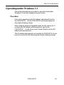
Operating under Windows 95
This section describes the procedure for using the board under
Windows 95 and lists a number of points to note.
Procedure
When using the board under Windows 95, the OS must be set to
recognize the I/O address and interrupt level used by the
COM-2(PC)F. In Windows 95, this is called hardware installation.
Use the following installation procedure.
Check the Current Settings
First, check the current settings. Check which interrupt levels are
available. If using in Compatible mode, also check which COM
ports (COM1 to COM4) are already set. The COM-2(PC)F cannot
be assigned to a COM port that is already set. The procedure for
checking is as follows.
- Check the interrupt level
1. Select [System] from [Control Panel] and open [Device
Manager].
2. Select the [Computer] folder and click [Properties].
3. Display the [Interrupt request(IRQ)] list and check which
interrupt levels are available.
- Check the ports
1. Select [System] from [Control Panel] and open [Device
Manager].
2. Double click on the [Ports (COM & LPT)] folder and check
which ports are already set.

How to Use the Board
COM-2(PC)F 11
Compatible Mode Installation Procedure 1
1. Set the operation mode (I/O address) and interrupt level for the
COM-2(PC)F. Set the COM-2(PC)F switch and jumpers as
described in Hardware Setup. Set an interrupt level that is not
currently used by the computer.
2. Insert the COM-2(PC)F in an expansion slot and turn on the
power to the PC.
3. After Windows 95 starts, select [Control Panel] from
[My Computer] and start the [Add New Hardware].
4. Click [Next >] in response to [To begin installing your new
hardware, click Next] in the Add New Hardware Wizard.
5. Select [Yes (Recommended)] in response to [Do you want
Windows to search for your new hardware ?].
6. After following the instructions and completing detection, use
[Details...] to check that the standard serial ports have been
detected.
7. Next, click [Finish] and restart your computer.
8. After rebooting, use the procedure described in the "Check
Resources" section below to check the interrupt level assigned
to the COM-2(PC)F. If the value is different to the level set on
the jumper, correct the setting in the OS.
9. When installing by this method, the COM-2(PC)F channels are
installed as standard serial ports (COM*).
Page is loading ...
Page is loading ...
Page is loading ...
Page is loading ...
Page is loading ...
Page is loading ...
Page is loading ...
Page is loading ...
Page is loading ...
Page is loading ...
Page is loading ...
Page is loading ...
Page is loading ...
Page is loading ...
Page is loading ...
Page is loading ...
Page is loading ...
Page is loading ...
Page is loading ...
Page is loading ...
Page is loading ...
Page is loading ...
Page is loading ...
Page is loading ...
Page is loading ...
Page is loading ...
Page is loading ...
Page is loading ...
Page is loading ...
Page is loading ...
Page is loading ...
Page is loading ...
Page is loading ...
Page is loading ...
Page is loading ...
Page is loading ...
Page is loading ...
Page is loading ...
Page is loading ...
Page is loading ...
Page is loading ...
Page is loading ...
Page is loading ...
Page is loading ...
Page is loading ...
Page is loading ...
Page is loading ...
Page is loading ...
Page is loading ...
Page is loading ...
Page is loading ...
Page is loading ...
Page is loading ...
Page is loading ...
Page is loading ...
Page is loading ...
Page is loading ...
-
 1
1
-
 2
2
-
 3
3
-
 4
4
-
 5
5
-
 6
6
-
 7
7
-
 8
8
-
 9
9
-
 10
10
-
 11
11
-
 12
12
-
 13
13
-
 14
14
-
 15
15
-
 16
16
-
 17
17
-
 18
18
-
 19
19
-
 20
20
-
 21
21
-
 22
22
-
 23
23
-
 24
24
-
 25
25
-
 26
26
-
 27
27
-
 28
28
-
 29
29
-
 30
30
-
 31
31
-
 32
32
-
 33
33
-
 34
34
-
 35
35
-
 36
36
-
 37
37
-
 38
38
-
 39
39
-
 40
40
-
 41
41
-
 42
42
-
 43
43
-
 44
44
-
 45
45
-
 46
46
-
 47
47
-
 48
48
-
 49
49
-
 50
50
-
 51
51
-
 52
52
-
 53
53
-
 54
54
-
 55
55
-
 56
56
-
 57
57
-
 58
58
-
 59
59
-
 60
60
-
 61
61
-
 62
62
-
 63
63
-
 64
64
-
 65
65
-
 66
66
-
 67
67
-
 68
68
-
 69
69
-
 70
70
-
 71
71
-
 72
72
-
 73
73
-
 74
74
-
 75
75
-
 76
76
-
 77
77


Contec Contec COM-2(PC)F User manual
- Type
- User manual
- This manual is also suitable for
Ask a question and I''ll find the answer in the document
Finding information in a document is now easier with AI
Related papers
-
Contec COM-2C-LPE Owner's manual
-
-
-
-
-
Contec SMC-8DL-PCI Owner's manual
-
-
-
-
Contec DIO-32DM2-PE Owner's manual

