Page is loading ...

For more information, visit www.desatech.com
WARNING: If the information in this manual is not fol-
— WHAT TO DO IF YOU SMELL GAS
• Do not touch any electrical switch; do not use any
-
UNVENTED (VENT-FREE) GAS
COMPACT CLASSIC HEARTH
®
FIREPLACE
OWNER’S OPERATION AND INSTALLATION MANUAL
THERMOSTAT MODELS:
VMH10TNC, VMH10TPC, EFS10TPA AND EFS10TNA
REMOTE-READY MODELS:
VMH10RNC, VMH10RPC, EFS10RPA, EFS10RNA, CGCF10NR
AND CGCF10PR
Shown with
Mantel/Hearth Base
Accessory

www.desatech.com
112462-01G2
SAFETY INFORMATION
TABLE OF CONTENTS
Safety Information ............................................... 2
Local Codes......................................................... 4
Product Identication ........................................... 5
Unpacking............................................................ 5
Product Features ................................................. 5
Optional Remote Control Accessories ................. 5
Assembly ............................................................. 6
Air for Combustion and Ventilation ...................... 7
Installation ........................................................... 9
Operating Fireplace ........................................... 23
Inspecting Burners............................................. 29
Cleaning and Maintenance ................................ 30
Troubleshooting ................................................. 31
Specications .................................................... 35
Wiring Diagram .................................................. 35
Service Hints ..................................................... 35
Technical Service............................................... 35
Replacement Parts ............................................ 35
Illustrated Parts Breakdown and Parts List........ 36
Accessories ....................................................... 40
Warranty Information ...........................Back Cover
-
-
teration, service or main-
tenance can cause in-
Refer to this manual for
correct installation and
For assistance or addi-
tional information con-
WARNING: This is an
-
from the room in which
and ventilation air must
Air
for Combustion and Ven-
tilation
-
stalled in an aftermarket,*
-
State of Massachusetts: The installation
must be made by a licensed plumber or
gas tter in the Commonwealth of Mas-
sachusetts.
Sellers of unvented propane or natural
gas-red supplemental room heaters shall
provide to each purchaser a copy of 527
CMR 30 upon sale of the unit.
Vent-free gas products are prohibited for
bedroom and bathroom installation in the
Commonwealth of Massachusetts.

www.desatech.com
112462-01G 3
-
known to the State of California
-
-
Early signs of carbon
monoxide poisoning resemble the u, with head-
aches, dizziness or nausea. If you have these signs,
the replace may not be working properly. Get
fresh air at once! Have replace serviced. Some
people are more affected by carbon monoxide than
others. These include pregnant women, people with
heart or lung disease or anemia, those under the
inuence of alcohol and those at high altitudes.
Natural and pro-
pane/LP gases are odorless. An odor-making agent
is added to the gas. The odor helps you detect a gas
leak. However, the odor added to the gas can fade.
Gas may be present even though no odor exists.
Make certain you read and understand all warnings.
Keep this manual for reference. It is your guide to
safe and proper operation of this replace.
-
SAFETY INFORMATION
Continued
WARNING: Do not allow fans
-
away from hot surfaces to avoid
-
-
dren when they are in the room
hand-held remote accessory
-
-

www.desatech.com
112462-01G4
SAFETY INFORMATION
Continued
1. This appliance is only for use with the type of
gas indicated on the rating plate. This appliance
is not convertible for use with other gases.
2. Do not place propane/LP supply tank(s) in-
side any structure. Locate propane/LP supply
tank(s) outdoors.
3. If you smell gas
• shut off gas supply
• do not try to light any appliance
• do not touch any electrical switch; do not use
any phone in your building
• immediately call your gas supplier from a
neighbor’s phone. Follow the gas supplier’s
instructions
• if you cannot reach your gas supplier, call
the re department
4. This replace shall not be installed in a bath-
room.
5. Do not use this replace as a wood-burning
replace. Use only the logs provided with the
replace.
6. Do not add extra logs or ornaments such as
pine cones, vermiculite or rock wool. Using
these added items can cause sooting. Do not
add lava rock around base. Rock and debris
could fall into the control area of replace.
7. This replace is designed to be smokeless.
If logs ever appear to smoke, turn off re-
place and call a qualified service person.
Note: During initial operation, slight smoking
could occur due to log curing and replace
burning manufacturing residues.
8. To prevent the creation of soot, follow the instruc-
tions in Cleaning and Maintenance, page 30.
9. Before using furniture polish, wax, carpet
cleaner or similar products, turn replace off.
If heated, the vapors from these products may
create a white powder residue within burner
box or on adjacent walls or furniture.
10. This replace needs fresh air ventilation to run
properly. This replace has an Oxygen Deple-
tion Sensing (ODS) safety shutoff system. The
ODS shuts down the replace if not enough
fresh air is available. See Air for Combustion
and Ventilation, page 7. If replace keeps
shutting off, see Troubleshooting, page 31.
11. Keep all air openings in front and at bottom
of heater clear and free of debris. This will
insure enough air for proper combustion.
12. Do not run replace
• where ammable liquids or vapors are used
or stored.
• under dusty conditions.
13. Do not use this replace to cook food or burn
paper or other objects.
14. Never place any objects in the replace or
on logs.
15. Do not use replace if any part has been under
water. Immediately call a qualied service
technician to inspect the room replace and to
replace any part of the control system and any
gas control which has been under water.
16. Turn off and unplug replace and let cool
before servicing. Only a qualied service
person should service and repair replace.
17. Operating replace above elevations of 4,500
feet could cause pilot outage.
18. Do not operate replace if any log is broken.
Do not operate replace if a log is chipped
(dime-sized or larger).
19.
To prevent performance problems, do not use
propane/LP fuel tank of less than 100 lbs.
capacity.
20. Provide adequate clearances around air
openings.
LOCAL CODES
Install and use replace with care. Follow all local
codes. In the absence of local codes, use the lat-
est edition of The National Fuel Gas Code ANSI
Z223.1/NFPA 54*.
*Available from:
American National Standards Institute, Inc.
1430 Broadway
New York, NY 10018
National Fire Protection Association, Inc.
Batterymarch Park
Quincy, MA 02269

www.desatech.com
112462-01G 5
PRODUCT
IDENTIFICATION
Electronic Ignitor
Button
Screen
Fireplace
Cabinet
Logs
Control Knob
Figure 1 - Vent-Free Compact Classic
Hearth
®
Fireplace
Screen
Fireplace Cabinet
Logs
Electronic
Ignitor Button
Remote Control
(Optional)
Remote
Selector
Switch
(Optional)
Control Knob
Flexible Gas
Line
Flexible
Gas
Line
UNPACKING
1. Remove fireplace and hood from carton.
Log is wrapped and inside replace. Do not
remove at this time.
2. Remove all protective packaging applied to
replace for shipment.
3. Make sure your replace includes one hard-
ware packet.
4. Check replace for any shipping damage. If
replace is damaged, promptly inform dealer
where you bought replace.
PRODUCT FEATURES
SAFETY PILOT
This replace has a pilot with an Oxygen Deple-
tion Sensing (ODS) safety shutoff system. The
ODS/pilot is a required feature for vent-free room
replaces. The ODS/pilot shuts off the replace if
there is not enough fresh air.
ELECTRONIC IGNITOR
This heater has an electronic ignitor to light heater
fuel supply.
THERMOSTATIC HEAT CONTROL
FOR THERMOSTAT-CONTROLLED
MODELS
Thermostat-Controlled models have a thermostat
sensing bulb and a control valve. The thermostat
will automatically modulate the heat output to
maintain a consistent room temperature. This
results in greater replace comfort. This can also
result in lower gas bills.
OPTIONAL REMOTE
CONTROL ACCESSORIES
There are four optional remote controls that
can be purchased separately for Remote-Ready
Models only:
• wall switch
• hand-held ON/OFF remote
• wall thermostat
• hand-held thermostat remote
See Accessories, page 40.

www.desatech.com
112462-01G6
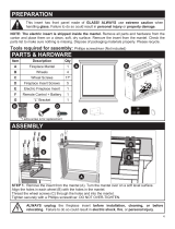
ASSEMBLY
WARNING: Always have
-
-
ASSEMBLING FIREPLACE
Tools Required:
• Phillips screwdriver
• 5/16" hex wrench
• slotted screwdriver
• scissors
1. Remove two screws that hold replace screen
in place for shipping. These screws are located
near top of screen. Discard screws. Lift re-
place screen up and pull out to remove (see
Figure 2). Set screen aside until installation
has been completed.
2. Cut two plastic straps to remove the log from
the rebox cavity.
3. An optional blower is available. See Acces-
sories, page 40. Install optional blower now.
Follow installation instructions provided with
blower. See Installing Optional Blower Acces-
sory GA3450TA on page 14.
Screen
Shoulder
Screw
Figure 3 - Assembling Hood
Sheet Metal
Screws
Louver
Hood
Hood Tabs
Hood Tab
Bafe
Firebox Top
Figure 2 - Removing Screen
4. Locate four black Phillips sheet metal screws
from the hardware packet.
5. Rotate hood as shown in Figure 3. Make sure
hood tabs point toward replace.
6. Insert hood tabs between bafe and louvers
(see Figure 3).
7. Gently rotate hood to upright position. Make
sure hood tabs are behind louvers and hood
is resting on rebox top (see Figure 3).
8. Align screw holes on hood with screw holes
on rebox top.
9. Insert screws as shown in Figure 3. Tighten
screws rmly.

www.desatech.com
112462-01G 7
AIR FOR COMBUSTION
AND VENTILATION
-
-
Today’s homes are built more energy efcient
than ever. New materials, increased insulation and
new construction methods help reduce heat loss
in homes. Home owners weather strip and caulk
around windows and doors to keep the cold air out
and the warm air in. During heating months, home
owners want their homes as airtight as possible.
While it is good to make your home energy ef-
cient, your home needs to breathe. Fresh air must
enter your home. All fuel-burning appliances need
fresh air for proper combustion and ventilation.
Exhaust fans, replaces, clothes dryers and fuel
burning appliances draw air from the house to
operate. You must provide adequate fresh air for
these appliances. This will insure proper venting
of vented fuel-burning appliances.
PROVIDING ADEQUATE
VENTILATION
The following are excerpts from National Fuel
Gas Code. ANSI Z223.1/NFPA 54, Section 5.3,
Air for Combustion and Ventilation.
All spaces in homes fall into one of the three fol-
lowing ventilation classications:
1. Unusually Tight Construction
2. Unconned Space
3. Conned Space
The information on pages 7 through 9 will help
you classify your space and provide adequate
ventilation.
The air that leaks around doors and windows may
provide enough fresh air for combustion and ven-
tilation. However, in buildings of unusually tight
construction, you must provide additional fresh air.
construction where:
-
2
and
and
If your home meets all of these three
Ventilation Air From
Outdoors
If your home does not meet all of the
Deter-
mining Fresh-Air Flow For Fireplace
Location
The National Fuel Gas Code, ANSI Z223.1/NFPA
54 defines a confined space as a space whose
volume is less than 50 ft
3
per 1,000 Btu/hr (4.8 m
3
/
kw) of the aggregate input rating of all appliances
installed in that space and an unconned space as a
space whose volume is not less than 50 ft
3
per 1,000
Btu/hr (4.8 m
3
/kw) of the aggregate input rating
of all appliances installed in that space. Rooms
communicating directly with the space in which
the appliances are installed*, through openings not
furnished with doors, are considered a part of the
unconned space.
* Adjoining rooms are communicating only if
there are doorless passageways or ventilation grills
between them.

www.desatech.com
112462-01G8
DETERMINING FRESH-AIR FLOW
FOR FIREPLACE LOCATION
Use this work sheet to determine if you have a
conned or unconned space.
Includes the room in which you will install
replace plus any adjoining rooms with doorless pas-
sageways or ventilation grills between the rooms.
1. Determine the volume of the space (length x
width x height).
Length x Width x Height =__________cu. ft.
(volume of space)
Example: Space size 16 ft. (length) x 14 ft.
(width) x 8 ft. (ceiling height) = 1792 cu. ft.
(volume of space)
If additional ventilation to adjoining room is
supplied with grills or openings, add the volume
of these rooms to the total volume of the space.
2. Multiply the space volume by 20 to determine
the maximum Btu/Hr the space can support.
__________ (volume of space) x 20 = (Maximum
Btu/Hr the space can support)
Example: 1792 cu. ft. (volume of space) x 20 =
35,840 (maximum Btu/Hr the space can support)
3. Add the Btu/Hr of all fuel burning appliances in
the space.
Vent-free replace __________ Btu/Hr
Gas water heater* __________ Btu/Hr
Gas furnace __________ Btu/Hr
Vented gas heater __________ Btu/Hr
Gas replace logs __________ Btu/Hr
Other gas appliances* + __________ Btu/Hr
Total = __________ Btu/Hr
* Do not include direct-vent gas appliances. Di-
rect-vent draws combustion air from the outdoors
and vents to the outdoors.
Example:
Gas water heater __________ Btu/Hr
Vent-free replace + __________ Btu/Hr
Total = __________ Btu/Hr
4. Compare the maximum Btu/Hr the space can
support with the actual amount of Btu/Hr used.
__________ Btu/Hr (maximum the space can support)
__________ Btu/Hr (actual amount of Btu/Hr used)
Example: 35,840 Btu/Hr (maximum the space
can support)
40,000 Btu/Hr (actual amount of
Btu/Hr used)
The space in the example is a conned space because
the actual Btu/Hr used is more than the maximum
Btu/Hr the space can support. You must provide ad-
ditional fresh air. Your options are as follows:
A. Rework worksheet, adding the space of an adjoin-
ing room. If the extra space provides an unconned
space, remove door to adjoining room or add
ventilation grills between rooms. See Ventilation
Air From Inside Building.
B. Vent room directly to the outdoors. See Ventila-
tion Air From Outdoors.
C. Install a lower Btu/Hr replace, if lower Btu/Hr
size makes room unconned.
If the actual Btu/Hr used is less than the maximum Btu/Hr
the space can support, the space is an unconned space.
You will need no additional fresh air ventilation.
WARNING: If the area in which
in the National Fuel Gas Code,
VENTILATION AIR
This fresh air would come from an adjoining un-
conned space. When ventilating to an adjoining
unconned space, you must provide two permanent
openings: one within 12" of the ceiling and one
within 12" of the oor on the wall connecting the
two spaces (see options 1 and 2, Figure 4, page 9).
You can also remove door into adjoining room (see
option 3, Figure 4, page 9). Follow the National Fuel
Gas Code, ANSI Z223.1/NFPA 54, Section 5.3, Air
for Combustion and Ventilation for required size
of ventilation grills or ducts.
Ventilation Air From Outdoors
Provide extra fresh air by using ventilation grills or
ducts. You must provide two permanent openings:
one within 12" of the ceiling and one within 12"
of the oor. Connect these items directly to the
outdoors or spaces open to the outdoors. These
spaces include attics and crawl spaces. Follow the
National Fuel Gas Code, ANSI Z223.1/NFPA 54,
Section 5.3, Air for Combustion and Ventilation for
required size of ventilation grills or ducts.
AIR FOR COMBUSTION
AND VENTILATION
Continued
30,000
10,000
40,000

www.desatech.com
112462-01G 9
IMPORTANT: Do not provide openings for inlet
or outlet air into attic if attic has a thermostat-
controlled power vent. Heated air entering the attic
will activate the power vent.
AIR FOR COMBUSTION
AND VENTILATION
Continued
Figure 4 - Ventilation Air from Inside
Building
Or
Remove
Door into
Adjoining
Room,
Option 3
Ventilation Grills
Into Adjoining Room,
Option 2
12"
12"
Ventilation
Grills
into
Adjoining
Room,
Option 1
Figure 5 - Ventilation Air from Outdoors
Outlet
Air
Ventilated
Attic
Outlet
A
ir
Inlet
Air
Inlet Air
Ventilated
Crawl Space
To
Crawl
Space
To Attic
INSTALLATION
NOTICE: This heater is intended
-
WARNING: Never install the
• in a recreational vehicle
• where curtains, furniture,
• in windy or drafty areas
-
currents move heat to wall sur-
-
in the air exist, may discolor walls

www.desatech.com
112462-01G10
IMPORTANT: Vent-free replaces add moisture
to the air. Although this is benecial, installing re-
place in rooms without enough ventilation air may
cause mildew to form from too much moisture. See
Air for Combustion and Ventilation, page 7.
Note: Your replace is designed to be used in zero
clearance installations. Wall or framing material can be
placed directly against any exterior surface on the rear,
sides or top of your replace, except where standoff
spacers are integrally attached. If standoff spacers are
attached to your replace, these spacers can be placed
directly against wall or framing materials.
Note: When installing replace directly on carpet-
ing, tile or other combustible material, other than
wood ooring, the replace shall be installed on a
metal or wood panel extending the full width and
depth of the replace.
Use the dimensions shown for rough openings to
create the easiest installation (see Built-In Fire-
place Installation, page 11).
Use the correct gas type (natural or propane/LP)
for your unit. If your gas supply is not correct, do
not install replace. Call dealer where you bought
replace for proper type replace.
-
INSTALLATION ITEMS
Before installing replace, make sure you have
the items listed below.
• external regulator (supplied by installer, for
propane/LP units only)
• piping (check local codes)
• sealant (resistant to propane/LP gas)
• equipment shutoff valve *
• test gauge connection*
• ground joint union
• sediment trap
• tee joint
• pipe wrench
* A CSA design-certied equipment shutoff valve
with 1/8" NPT tap is an acceptable alternative to
test gauge connection. Purchase the optional CSA
design-certied equipment shutoff valve from your
dealer. See Accessories, page 40.
INSTALLATION
Continued
FIREPLACE CLEARANCES
WARNING: Maintain the
minimum clearances shown in
-
-
-
If your replace is to be used with an optional
mantel, the installation instructions included with
your mantel shows an CSA approved method of
attaching the replace/mantel system to a wall.
IMPORTANT: Only use optional cabinet or
corner mantels specied in this manual. Purchase
the optional mantel from your dealer (see Acces-
sories, page 40).
If your replace is to be recessed into the wall,
see Built-In Fireplace Installation on page 11 to
secure your replace into the wall.
CAUTION: If you install the
For convenience and efciency, install replace
• where there is easy access for operation, inspec-
tion and service
• in coldest part of room
An optional blower kit is available from your
dealer. See Accessories, page 40. If planning to use
blower, follow instructions provided with blower
for power source.

www.desatech.com
112462-01G 11
A. Clearances from the side of the fireplace
cabinet to any combustible material and wall
should follow diagram in Figure 6.
Example: The face of a mantel, bookshelf,
etc. is made of combustible material and
protrudes 3
1
/
2
" from the wall. This combus-
tible material must be 4" from the side of the
replace opening (see Figure 6).
B.
Clearances from the top of the replace
opening to the ceiling should not be less
than 36".
C. For mantel clearances, see Figure 10 on
page 13.
Figure 6 - Minimum Clearance for
Combustible to Wall
*Minimum 16" from Side Wall
*
Example
MINIMUM CLEARANCE TO
COMBUSTIBLE MATERIALS
Left and
Bottom and
Rear
36"
6" 0"
INSTALLATION
Continued
Actual Framing
Height 26" 26
7
/8"
Front Width 26
3
/4" 26
7
/8"
Depth 9
1
/2" 10
1
/2"
Bottom 3/4" 3/4"
1. Frame in rough opening. Use dimensions shown
in Figure 7 for the rough opening. If installing in
a corner, use dimensions shown in Figure 8 for
the rough opening. The height is 26
7
/8" which
is the same as the wall opening above.
2. If installing GA3450TA blower accessory, do
so at this time. Follow instructions included
with blower accessory.
Note: If not installing blower accessory, you
may wish to run electrical wiring to your
replace for future blower installation (see
Accessories, page 40). Use only approved
three-wire electrical wiring.
-
-
cal outlet is included with the
-
Note: A qualied installer should make all electri-
cal connections.
BUILT-IN FIREPLACE INSTALLATION
Built-in installation of this replace involves install-
ing replace into a framed-in enclosure. This makes
the front of replace ush with wall. An optional
trim kit accessory is available (see Accessories,
page 40). Trim will extend past sides of replace
approximately 1/2". This will cover the rough edges
of the wall opening. If installing a built-in mantel
above the replace, you must follow the clearances
shown in Figure 10, page 13. Follow the instruc-
tions below to install the replace in this manner.
26
7
/8
"
26
7
/8
"
3/4" Off
The Floo
r
Minimum
10
1
/2
"
Figure 8 - Rough Opening for Installing
in Corner
Figure 7 - Rough Opening for Installing
in Wall
36
5
/
8
"
25
7
/
8
"
51
3
/
4
"
26
7
/
8
"

www.desatech.com
112462-01G12
3. Install gas piping to replace location. This
installation includes an approved exible gas
line (if allowed by local codes) after the equip-
ment shutoff valve. The exible gas line must
be the last item installed on the gas piping.
4. If you have not assembled rebox, follow
instructions on page 6.
5. Carefully set replace in front of rough opening
with back of replace inside wall opening.
6. Attach exible gas line to replace gas regula-
tor. See Connecting Fireplace to Gas Supply,
page 19.
7. Bend four nailing anges on outer casing with
pliers (see Figure 9).
8. Attach fireplace to wall studs using nails
or wood screws through holes in nailing
ange.
9. Check all gas connections for leaks. See
Checking Gas Connections, page 19.
10. If using optional trim kit, install the trim after
nal nishing and/or painting of wall. See
instructions included with trim accessory for
attaching trim.
IMPORTANT: When finishing your firebox,
combustible materials such as wall board, gypsum
board, sheet rock, drywall, plywood, etc. may be
butted up next to the sides and top edge of the re-
box. Combustible materials should never overlap
the rebox front facing.
INSTALLATION
Continued
Figure 9 - Attaching Fireplace to Wall
Studs
Nailing
Flanges
Nails or
Wood
Screws
Wall
Studs
WARNING: Do not allow any
WARNING: Do not allow
WARNING: Never modify or
cover the louvered slots on the
Mantel Clearances for Built-In
Installation
If placing mantel above built-in replace, you must
meet minimum clearance between mantel shelf and
top of replace opening.
minimum clearances shown in
NOTICE: If your installation
does not meet the minimum
-
• remove the mantel

www.desatech.com
112462-01G 13
Mantel Shelf
13"
16"
19"
21"
2
1
/2"
6"
8"
10"
Note:
A
ll vertical
measurements
are from top of
fireplace
opening to
bottom of
mantel shelf. All
measurements
are in inches.
Figure 10 - Minimum Mantel Clearances
for Built-In Installation
INSTALLATION
Continued
OPTIONAL MANTEL INSTALLATION
Refer to instructions provided with the mantel
for assembly instructions. Refer to the follow-
ing instructions for system installation. Refer to
instructions on page 6 for hood assembly. Blower
accessory should be installed prior to mantel if it
is being used (see Installing Optional Blower Ac-
cessory GA3450TA, page 14).
1. Assemble cabinet mantel as shown in acces-
sory instruction sheet.
2. If blower is installed, install a properly
grounded, 120 volt three-prong electrical out-
let at replace location if an outlet is not there.
If possible, locate outlet so cabinet mantel will
cover it when installed (see Figure 11).
3. Place hearth base against wall at installation
location. Cut an access hole in hearth base to
run gas line to replace (see Figure 11). Make
sure to locate access hole so cabinet mantel will
cover it when installed. Note: You can secure
base to oor using wood screws. Countersink
screw heads and putty over.
4. Route exible gas line through access hole in
hearth base.
5. Center cabinet mantel on hearth base (see
Figure 12). Make sure mantel is ush against
wall and centered left to right on base.
6. Use screws provided with mantel accessory
to attach mantel assembly to base (see mantel
instruction sheet).
7. Attach exible gas line to replace gas regula-
tor. See Connecting to Gas Supply, page 17.
8. Route electrical cord(s) through access holes
in either side of replace with bushing. Plug
electrical cord(s) into electrical outlet.
9. Check all gas connections for leaks. See
Checking Gas Connections, page 19.
10. Carefully insert replace into cabinet mantel
(see Figure 13). Be careful not to scratch or
damage hearth base or cabinet mantel.
11. Place metal trim on shoulder screws located
on the side and top of the replace (see Assem-
bling Perimeter Trim, page 14). Firmly snap
trim over shoulder screws. Align replace in
mantel assembly so the trim overlaps mantel
evenly on all three sides.
12.
Lower bottom louver door. Use 3" wood screws
provided with mantel accessory to attach re-
place to base (see mantel instruction sheet).
Side of Firebox
Figure 11 - Placing Hearth Base Against Wall
Hearth
Base
Electrical
Outlet
Pipe and Gas
Shutoff Valve
Figure 12 - Installing Cabinet Mantel onto
Hearth Base
Cabinet
Mantel
Hearth
Base
O
F
F
P
I
L
O
T
O
N
H
I
L
O
Figure 13 - Installing Fireplace into
Mantel Assembly
Cabinet
Mantel
Assembled
Trim
Hearth Base

www.desatech.com
112462-01G14
1. Remove packaging from three remaining
pieces of trim.
2. Locate two adjusting plates with set screws
and two shims in the hardware packet.
3. Align shim under adjusting plate as shown in
Figure 14.
4. Slide one end of adjusting plate/shim in slot
on mitered edge of top trim (see Figure 14).
5. Slide other end of adjusting plate/shim in slot
on mitered edge of side trim (see Figure 14).
6. While rmly holding edges of trim together,
tighten both set screws on the adjusting plate
with slotted screwdriver.
7. Repeat steps 1 through 6 for other corner.
8. Set assembly aside for later installation.
Figure 14 - Assembling Trim
Side Trim
Top Trim
Mitered Edge
Shim
Set
Screws
Adjusting Plate
Slot
Figure 15 - Removing Upper Louver
Blower
Bracket
Mounting
Holes
INSTALLING OPTIONAL BLOWER
To install the blower accessory, you must rst
remove the upper louver.
1. Lift screen off replace and remove log set if
installed.
2. Remove 4 screws from upper louver (see
Figure 15). Save these screws.
3. Pull upper louver straight out from the cabinet.
Be careful not to scratch the paint. Set louver
and screws aside.
4. Open lower louver door by swinging door
down (see Figure 16, page 15).
Upper Louver
INSTALLATION
Continued
Note: If you are using a mantel with your replace,
use the following instructions. If your replace is
built-in, see For Built-In Installation, page 16.
-
-
1. Locate fan switch cover. Remover bottom
screw to remove back portion of the cover.
2. Install snap bushings found in hardware kit
into both holes in rear of fan switch cover.
3. Make sure the wire harness is rmly con-
nected to the terminals on the blower bracket
assembly.
4. Note the wire locations on back of AUTO/
OFF/ON switch. The terminals on back of
switch are numbered 1, 2 and 3. Carefully
remove red wire from terminal 3 and blue wire
from terminal 1. Black wire can remain on
middle terminal 2 (see Figure 16, page 15).
5. Carefully disconnect green and white wires
at their insulated connectors (see Figure 17,
page 15).

www.desatech.com
112462-01G 15
3
2
1
Figure 16 - Installing Blower (Thermostat Unit Shown)
Wire Harness
Blower Bracket Assembly
Screw
Wire
Harness
Switch
Bafe
Wiring Routing Hole
in Bafe
Switch
Plate
Blue
Red
Rear Fan
Switch Cover
Snap
Bushing
Power Cord
Black
Blower Mounting
Holes
Lower Louver Door
Front Fan
Switch
Cover
INSTALLATION
Continued
6. In top of the replace cabinet, locate the
four mounting holes on the outer casing.
Align these four holes with those on the
blower bracket assembly. Attach blower
bracket assembly to the outer casing with
4 #10 screws provided (see Figure 16).
7. Route the wire harness through the hole
in left side of bafe. Pull wire harness
through lower opening of firebox (see
Figure 16).
8.
Insert the 4 wire harnesses into one of the
round holes in the rear of the fan switch cover
and through the rectangular hole on front of
the fan switch cover (see Figure 16).
9. Reconnect red wire to switch position 3.
Reconnect blue wire to switch position 1.
Reconnect green and white wires.
10. Install the switch plate on front of fan
switch cover with 2 #10 screws provided
(see Figure 18, page 16). Using screw
removed in step one, reconnect front and
rear of fan switch cover.
Figure 17 - Wiring Diagram For Blower
Accessory Standard Installation
Red
Red
Fan Switch
(Auto/Off/On)
Blue
Blue
Thermostat
Switch
(N.O.)
Green
White
Green
White
On
110/115
V.A.C.
Blower
Motor
Black
Off
1
2
3
Auto

www.desatech.com
112462-01G16
11. Route power cord out of the cabinet by insert-
ing it through the bushing on the outer casing
(see Figure 16, page 15). Plug fan kit into 120
Volt grounded power supply and test opera-
tion. Note: When switch is in the AUTO posi-
tion, the fan will start after the replace has
run for a few moments. The fan will continue
to run for several moments after the replace
has been turned off. When switch is in the ON
position, the fan will run until turned to OFF.
Reinstall upper louver (see Figure 15, page
14). Close lower louver door.
INSTALLATION
Continued
Red
Red
Fan Switch
(Auto/Off/On)
Blue
Blue
Thermostat
Switch
(N.O.)
Green
White
Green
White
On
110/115
V.A.C.
Blower
Motor
Black
Off
1
2
3
Auto
Figure 19 - Wiring Diagram For Blower
Accessory Built-In Installation
For Built-In Installation
WARNING: A licensed elec-
-
1. Locate fan switch cover. Remove bottom
screw to remove back portion of the cover
(see Figure 18).
2. Install a snap bushing found in hardware kit into
one of the holes on rear of fan switch cover. The
other hole is for a strain relief clamp (not sup-
plied) to secure incoming electrical supply.
3. Follow steps 3 through 7 in Installing Blower
Accessory, page 14.
4. A licensed electrician must follow the wiring
diagram to connect incoming electrical supply
to fan kit wiring harness (see Figure 19).
Figure 18 - Installing Switch Plate to Fan
Switch Cover
Switch
Cover
Screw
Screw
Rear
- Fan
Switch
Cover
Front - Fan
Switch Cover
Switch Plate
5. Install the switch plate on front of fan
switch cover with 2 #10 screws provided
(see Figure 18). Using screw removed in
step one, reconnect front and rear of fan
switch cover.
6. Plug power cord to the outlet receptacle (not
provided) as shown in Figure 20, page 17. Wind
extra cable of power cord and tie it up with the
plastic wire strap (see Figure 20, page 17). Set
the cable bundle between the fan switch box
and outer casing, away from the burner.
7. Test to make sure the blower is working
properly.
8.
Reinstall upper louver (see Figure 15, page 14)
and close lower louver.
Extension Cord
Use extension cord if needed. The cord must have
a three-prong, grounding plug and a three-hole
receptacle. Make sure cord is in good shape. It must
be heavy enough to carry the current needed. An un-
dersized cord will cause a drop in line voltage. This
will result in loss of power and overheating. Use a
No. 16 AWG cord for lengths less than 50 feet.

www.desatech.com
112462-01G 17
3
2
1
Figure 20 - Installing Blower (Thermostat Unit Shown)
Blower Bracket
Assembly
Screw
Wire Harness
Plastic
Wire
Strap
Wire
Harness
Switch
Plate
Switch
Outlet
Receptacle (not
included)
Power Cord
Lower Louver
Door
Blue
Red
Black
Clamp
Connector
(not included)
INSTALLATION
Continued
CONNECTING TO GAS SUPPLY
-
-
-
WARNING: Never connect
IMPORTANT: For natural gas, check gas line
pressure before connecting replace to gas line.
Gas line pressure must be no greater than 14" of
water. If gas line pressure is higher, heater regula-
tor damage could occur.
-
For propane/LP units, the installer must supply
an external regulator. The external regulator will
reduce incoming gas pressure. You must reduce
incoming gas pressure to between 11" and 14" of
water. If you do not reduce incoming gas pressure,
replace regulator damage could occur. Install
external regulator with the vent pointing down as
shown in Figure 21, page 18. Pointing the vent
down protects it from freezing rain or sleet.

www.desatech.com
112462-01G18
INSTALLATION
Continued
CAUTION: Use only new,
-
Installation must include an equipment shutoff
valve, union and plugged 1/8" NPT tap. Locate
NPT tap within reach for test gauge hook up.
NPT tap must be upstream from heater (see
Figure 22).
IMPORTANT: Install equipment shutoff valve
in an accessible location. The equipment shutoff
valve is for turning on or shutting off the gas to
the appliance.
Check your building codes for any special re-
quirements for locating equipment shutoff valve
to replaces.
Apply pipe joint sealant lightly to male NPT
threads. This will prevent excess sealant from
going into pipe. Excess sealant in pipe could result
in clogged replace valves.
We recommend that you install a sediment trap in
supply line as shown in Figure 22. Locate sediment
trap where it is within reach for cleaning. Install
in piping system between fuel supply and heater.
Locate sediment trap where trapped matter is not
likely to freeze. A sediment trap traps moisture
and contaminants. This keeps them from going
into replace controls. If sediment trap is not
installed or is installed wrong, replace may not
run properly.
Propane/LP
Supply Tank
External Regulator
Figure 21 - External Regulator With Vent
Pointing Down
Vent Pointing Down
* Purchase the optional CSA design-certified
equipment shutoff valve from your dealer. See
Accessories, page 40.
Figure 22 - Gas Connection
CSA Design-Certied
Equipment Shutoff Valve
With 1/8" NPT Tap*
3" Minimum
Approved
Flexible Gas
Line
Pipe Nipple Cap Tee Joint
From External
Regulator
(11" W.C.** to 14"
W.C. Pressure)
NATURAL
From Gas Meter
(5" W.C.** to 10.5"
W.C. Pressure)
Sediment Trap

www.desatech.com
112462-01G 19
CONNECTING FIREPLACE TO GAS
SUPPLY
Installation Items Needed
• Phillips screwdriver
• sealant (resistant to propane/LP gas, not pro-
vided)
-
1. Route exible gas line, included, from re-
place control to equipment shutoff valve
through side or rear access holes in outer
casing (see Figure 1, page 5).
2. Apply pipe joint sealant lightly to male threads
of gas connector attached to exible gas line/
equipment shutoff valve (see Figure 23).
3. Check all gas connections for leaks. See
Checking Gas Connections.
4. Feed exible gas line into replace base area
while replacing branch support. Make sure the
entire exible gas line is in replace base area.
INSTALLATION
Continued
Figure 23 - Attaching Flexible Gas Line
to Equipment Shutoff Valve
Flexible Gas Line
from Fireplace Gas
Regulator Provided
With Fireplace
To Gas Regulator
(Thermostat-Controlled
Models) or Control Valve
(Remote-Ready Models)
Equipment
Shutoff Valve
PROPANE/LP
To External
Regulator
NATURAL
To Gas Supply
and connections, internal and
external to unit, for leaks after
a noncorrosive leak detection
-
CAUTION: Make sure exter-
under Connecting to Gas Sup-
ply
PRESSURE TESTING GAS SUPPLY
PIPING SYSTEM
1. Disconnect appliance with its appliance main gas
valve (control valve) and equipment shutoff valve
from gas supply piping system. Pressures in excess
of 1/2 psig will damage heater regulator.
2. Cap off open end of gas pipe where equipment
shutoff valve was connected.

www.desatech.com
112462-01G20
3. Pressurize supply piping system by either
opening propane/LP supply tank valve for
propane/LP gas or opening main gas valve
located on or near gas meter for natural gas
or using compressed air.
4. Check all joints of gas supply piping system.
Apply noncorrosive leak detection uid to all
joints. Bubbles forming show a leak.
5. Correct all leaks at once.
6. Reconnect replace and equipment shutoff
valve to gas supply. Check reconnected ttings
for leaks.
1. Close equipment shutoff valve (see Figure 24).
2. Pressurize supply piping system by either
opening propane/LP supply tank valve for
propane/LP gas or opening main gas valve
located on or near gas meter for natural gas
or using compressed air.
3. Check all joints from gas meter to equipment
shutoff valve for natural gas or propane/LP
supply to equipment shutoff valve for
propane/LP (see Figures 25 or 26). Apply
noncorrosive leak detection uid to all joints.
Bubbles forming show a leak.
4. Correct all leaks at once.
INSTALLATION
Continued
Figure 24 - Equipment Shutoff Valve
Open
Closed
Equipment
Shutoff Valve
Figure 25 - Checking Gas Joints
(Propane/LP Only)
Propane/LP
Supply Tank
Equipment
Shutoff Valve
Gas Regulator or
Gas Control Valve
Equipment
Shutoff Valve
Gas
Meter
Figure 26 - Checking Gas Joints (Natural
Gas Only)
Gas Regulator or
Gas Control Valve
PRESSURE TESTING FIREPLACE GAS
CONNECTIONS
1. Open equipment shutoff valve (see Figure 24).
2. Open main gas valve located on or near gas
meter for natural gas or open propane/LP
supply tank valve.
3. Make sure control knob of replace is in the
OFF position.
4. Check all joints from equipment shutoff
valve to gas regulator (Thermostat-Controlled
Models) or to gas control valve (Remote-
Ready Models) (see Figures 25 or 26). Apply
noncorrosive leak detection uid to all joints.
Bubbles forming show a leak.
5. Correct all leaks at once.
6. Light replace (see Operating Fireplace, page
23). Check all other internal joints for leaks.
7. Turn off replace (see To Turn Off Gas to Appli-
ance, page 25 for Thermostat-Controlled Mod-
els or page 27 for Remote-Ready Models).
/