Page is loading ...

RDL-3000 M2M Solutions
70-00159-01-06 Proprietary Redline Communications © 2012 Pahge 1 of 65 kune 12, 2012
RDL-3000
Radio Platform
Installation Guidelines
1 Important Notices ................................................................... 8
2 Regulatory Notices ............................................................... 12
3 System Features ................................................................... 16
4 Site Survey Information ....................................................... 22
5 Installation Procedures ........................................................ 26
6 Synchronization .................................................................... 59

RDL-3000 INSTALLATION GUIDELINES
70-00159-01-06 Proprietary Redline Communications © 2012 Page 2 of 65 kune 12, 2012
Copyright Information
All rights reserved kune 12, 2012. The information in this document is proprietary to
Redline Communications Inc. This document may not in whole or in part be copied,
reproduced, or reduced to any medium without prior consent, in writing, from Redline
Communications Incorporated.
Contact Information:
Redline Communications Inc.
302 Town Centre Blvd.
Markham, ON
Canada L3R 0E8
Tel: +1.905.479.8344 Toll Free in North America: +1.866.633.6669
Fax: +1.905.479.5331
Web site:
www.rdlcom.com
Document Control:
70-00159-01-06-RDL-3000_SC-SU_Installation_Guide-20120612a.doc
Disclaimer
The statements, configurations, technical data, and recommendations in this document
are believed to be accurate and reliable, but are presented without express or implied
warranty. Additionally, Redline makes no representations or warranties, either expressed
or implied, regarding the contents of this product. Redline Communications shall not be
liable for any misuse regarding this product. The information in this document is subject
to change without notice. No part of this document shall be deemed to be part of any
warranty or contract unless specifically referenced to be part of such warranty or
contract within this document.
Software Versions
This manual describes operation using RDL-3000 SC / SU subscriber software release
v2.xx. This document may include references to features that are different or unavailable
in previous software releases. Refer to the product Release Notes for information about
specific software releases.

RDL-3000 INSTALLATION GUIDELINES
70-00159-01-06 Proprietary Redline Communications © 2012 Page 3 of 65 kune 12, 2012
TABLE OF CONTENTS
1 Important Notices ................................................................... 8
1.1 Service & Safety ................................................................................................. 8
1.2 Installation Safety .............................................................................................. 9
2 Regulatory Notices ............................................................... 12
FCC Notices: Deployment in USA ................................................................ 12
Industry Canada Notices: Deployment in Canada ........................................ 13
Brazil Anatel Notices: Deployment in Brazil .................................................. 15
WEEE Product Return Process .................................................................... 15
2.1 Service & Warranty Information ...................................................................... 15
3 System Features ................................................................... 16
3.1 Overview ........................................................................................................... 16
3.2 Features ............................................................................................................ 16
3.3 Interface Ports .................................................................................................. 17
Ethernet Port ................................................................................................ 17
GPS Antenna Port (RDL-3000-G) ................................................................ 17
Synchronization I/O Port (PPS) .................................................................... 18
RAS Smart Antenna Port (RDL-3000-M) ...................................................... 18
RF Ports ....................................................................................................... 19
3.4 Configuration and Management ..................................................................... 19
ClearView NMS Application ......................................................................... 19
Telnet (CLI) .................................................................................................. 19
Web Browser (HTTP) ................................................................................... 20
Audible Alignment Tool ................................................................................ 20
3.5 Mounting Kits ................................................................................................... 20
3.6 Grounding ........................................................................................................ 20
Ground Lug .................................................................................................. 20
PoE Power Adapter ...................................................................................... 21
4 Site Survey Information ....................................................... 22
4.1 Planning Activities ........................................................................................... 22
4.1.1 RF Interference ............................................................................................... 22
4.1.2 Path Profile ..................................................................................................... 22
4.1.3 RF and Network Information ........................................................................... 23
4.2 Materials ........................................................................................................... 24
4.2.1 Redline System Components ......................................................................... 24
4.2.2 Customer Supplied Materials .......................................................................... 25
5 Installation Procedures ........................................................ 26

RDL-3000 INSTALLATION GUIDELINES
70-00159-01-06 Proprietary Redline Communications © 2012 Page 4 of 65 kune 12, 2012
5.1 General Guidelines .......................................................................................... 26
5.1.1 Grounding ....................................................................................................... 26
5.1.2 Surge Protection ............................................................................................. 27
5.1.3 Protecting Cables from Abrasion and Temperature ......................................... 28
5.1.4 Ethernet Cable Drip-Loop ............................................................................... 29
5.2 Mounting Kits ................................................................................................... 30
5.2.1 Lightweight Mounting Kit ................................................................................. 30
5.2.2 Heavy-Duty Mounting Kit ................................................................................ 33
5.3 RF Ports ............................................................................................................ 36
5.3.1 RF Cable Connections .................................................................................... 36
5.3.2 Weatherproofing RF Ports............................................................................... 36
5.4 Ethernet Port .................................................................................................... 39
5.4.1 Ethernet Cable Connections ........................................................................... 39
Assembling the Ethernet Weatheproof Connector ........................................ 39
Disconnecting the Ethernet Cable ................................................................ 40
Weatherproofing the Ethernet Port ............................................................... 41
5.4.2 Ethernet Surge Protection ............................................................................... 42
Installing the Ethernet Line Protector (LP) Unit ............................................. 42
Installing the LP Mast Mount Kit ................................................................... 44
Weatherproofing the LP Ports ...................................................................... 45
5.4.3 Indoor PoE ...................................................................................................... 46
5.5 Configuration ................................................................................................... 47
5.5.1 Step 1: Login to RDL-3000 .............................................................................. 47
Telnet Access .............................................................................................. 48
Web Browser ............................................................................................... 48
5.5.2 Step 2: Restore Default Settings ..................................................................... 48
Factory Reset ............................................................................................... 48
Long Reset ................................................................................................... 49
5.5.3 Step 3: Install Options Key .............................................................................. 49
Operation with No Options Key .................................................................... 49
Enter Permanent Options Key ...................................................................... 49
5.5.4 Step 4: Required Wireless Settings ................................................................. 50
RF Power Settings ....................................................................................... 51
5.5.5 Step 5: Create and Enable a Wireless Link ..................................................... 53
Add a Subscriber Link .................................................................................. 53
Add a Service Group .................................................................................... 53
Add a Service ............................................................................................... 54
5.6 Antenna Alignment .......................................................................................... 55
5.6.1 Coarse Antenna Alignment ............................................................................. 55
Azimuth Alignment ....................................................................................... 55
Elevation Alignment ..................................................................................... 55
5.6.2 Antenna Medium Adjustment Using the Audible Adjustment Tool ................... 56
5.6.3 Antenna Fine Alignment Using RSSI and SINADR ......................................... 56
Subscriber Link Status Screen (Subscriber Only) ......................................... 57
Using the Web Alignment Tool (SS Only) ..................................................... 57

RDL-3000 INSTALLATION GUIDELINES
70-00159-01-06 Proprietary Redline Communications © 2012 Page 5 of 65 kune 12, 2012
Subscriber Links Summary Screen (Sector Controller Only) ........................ 58
6 Synchronization .................................................................... 59
6.1 GPS Antenna Installation ................................................................................ 60
6.1.1 Choosing the GPS Antenna Location .............................................................. 60
RF Interference ............................................................................................ 61
6.1.2 GPS Antenna Kit ............................................................................................. 61
6.2 Synchronize RDL-3000 Units .......................................................................... 62
6.2.1 Wiring the RDL-3000 for Synchronization ....................................................... 62
Cables and Connectors ................................................................................ 62
Termination .................................................................................................. 63
Synchronization Cable Kit ............................................................................ 63
6.2.2 Configure Synchronization Settings ................................................................ 64
Sync Talker .................................................................................................. 64
Sync Listeners ............................................................................................. 64
Sync Cable Termination ............................................................................... 64
LIST OF TABLES
Table 1: Notice - Electrical safety specifications ............................................................ 10
Table 2: Avis - Spécifications de sécurité électrique ...................................................... 11
Table 3: Notice - Recommended Safe Distances .......................................................... 12
Table 4: Notice - Recommended Safe Distances .......................................................... 14
Table 5: Avis - IC RF Distances de séparation sécuritaire recommandées .................... 14
Table 6: Site Survey - Path Profile Data ........................................................................ 22
Table 7: Site Survey - RF and Network Information ....................................................... 23
Table 8: Materials - Redline System Components ......................................................... 24
Table 9: Materials - Customer-Supplied Items ............................................................... 25
Table 10: Procedures - Lightweight Mounting Kit - Parts List ......................................... 31
Table 11: Procedures - Heavy Duty Mounting Bracket - Parts List ................................. 34
Table 12: Procedures - RF Port - Connector Torque Specifications ............................... 36
Table 13: Procedures - Ethernet Line Protector - Mounting Kit Parts List ...................... 44
Table 14: Procedures - Operation with No Options Key ................................................. 49
Table 15: Procedures - RDL-3000 Parameter Settings .................................................. 50
Table 16: Spec. - FCC & IC Antennas: 4.94 - 4.99 GHz PTP Operation ........................ 51
Table 17: Spec. - FCC & IC Certified Antennas: 5.8 GHz PTP Operation ...................... 51
Table 18: Spec. - FCC & IC Certified Antennas: 5.8 GHz PTP Band Edge Operation ... 52
Table 19: Spec. - FCC & IC Certified Antennas: 5.8 GHz PMP Operation ..................... 52
Table 20: Spec. - Synchronization Settings ................................................................... 64
LIST OF FIGURES
Figure 1: Notice - WEEE Logo ....................................................................................... 15
Figure 2: Features: System Components ...................................................................... 17
Figure 3: Features - RDL-3000-G with GPS Antenna, Sync, and Ethernet Ports ........... 17
Figure 4: Features - RDL-3000 with Sync Port and Ethernet Port .................................. 18
Figure 5: Features - RDL-3000-M with Ethernet Port and RAS Antenna Control Port .... 18
Figure 6: Features - RF Ports (Top View of Radio) ........................................................ 19
Figure 7: Features - Web Login to the RDL-3000 .......................................................... 20

RDL-3000 INSTALLATION GUIDELINES
70-00159-01-06 Proprietary Redline Communications © 2012 Page 6 of 65 kune 12, 2012
Figure 8: Features - Indoor Power-over-Ethernet (PoE) Module - AC Model ................. 21
Figure 9: Site Survey - Fresnel Zone Radius ................................................................. 22
Figure 10: Site Survey - Non-Line of Sight Deployment ................................................. 23
Figure 11: Materials - Redline System Components ...................................................... 24
Figure 12: Procedures - Installing Surge Protection ....................................................... 27
Figure 13: Procedures - Air Terminal for Tower and Pole Deployments ......................... 28
Figure 14: Procedures - Cable Protection - Spiroband ................................................... 28
Figure 15: Procedures - Ethernet Cable Drip Loop ........................................................ 29
Figure 16: Procedures - Lightweight Mounting Kit - Installed View ................................. 30
Figure 17: Procedures - Lightweight Mounting Kit - Bracket Arm ................................... 31
Figure 18: Procedures - Lightweight Mounting Kit - Assembly Drawing ......................... 32
Figure 19: Procedures - Lightweight Mounting Kit - Alternate Mounting Methods .......... 33
Figure 20: Procedures - Heavy-Duty Mounting Kit ......................................................... 33
Figure 21: Procedures - Heavy Duty Mounting Kit - Assembled View ............................ 34
Figure 22: Procedures - Heavy Duty Mounting Kit - Assembly Drawing ......................... 35
Figure 23: Procedures - RF Port - Weatherproofing Pt-1 ............................................... 37
Figure 24: Procedures - RF Port - Weatherproofing Pt-2 ............................................... 37
Figure 25: Procedures - RF Port - Weatherproofing Pt-3 ............................................... 37
Figure 26: Procedures - RF Port - Weatherproofing Pt-4 ............................................... 38
Figure 27: Procedures - Ethernet Port - Weatherproof Connector Assembly Drawing ... 39
Figure 28: Procedures - Ethernet Port - Weatherproof Connector Components ............ 40
Figure 29: Procedures - Ethernet Port - Ethernet Connector Locking Tab ..................... 40
Figure 30: Procedures - Ethernet Port - Weatherproofing Pt-1 ...................................... 41
Figure 31: Procedures - Ethernet Port - Weatherproofing Pt-2 ...................................... 41
Figure 32: Procedures - Ethernet Port - Weatherproofing Pt-3 ...................................... 42
Figure 33: Procedures - Ethernet Line Protector - Wiring Diagram ................................ 43
Figure 34: Procedures - Ethernet Line Protector - Identifying Terminal Connectors ....... 43
Figure 35: Procedures - Ethernet Surge Protection - Mast Mounting Kit ........................ 44
Figure 36: Procedures - Ethernet Surge Protector - Weatherproofing Pt-1 .................... 45
Figure 37: Procedures - Ethernet Surge Protector - Weatherproofing Pt-2 .................... 45
Figure 38: Procedures - Ethernet Surge Protector - Weatherproofing Pt-3 .................... 45
Figure 39: Procedures - Ethernet PoE - Indoor Power Module Pinout ........................... 46
Figure 40: Procedures - Basic Wiring Configuration for Web/Telnet Access .................. 47
Figure 41: Procedures - Configuration - Login Screen ................................................... 48
Figure 42: Procedures - Configuration - Product Options Screen .................................. 50
Figure 43: Procedures - RDL-3000 Basic Pass-Through Configuration ......................... 53
Figure 44: Procedures - Antenna Alignment - Zero the Antenna Elevation Plane .......... 55
Figure 45: Procedures - Subscriber Link Status Screen ................................................ 57
Figure 46: Procedures - Antenna Alignment Tool Screen .............................................. 57
Figure 47: Procedures - Web Antenna Alignment Tool Using Wi-Fi ............................... 58
Figure 48: Procedures - Subscriber Links Summary Screen .......................................... 58
Figure 49 - Sync - Geographically Collocated RF Cells ................................................. 59
Figure 50 - Sync - Geographically Isolated RF Cell ....................................................... 59
Figure 51 - Sync - Collocated RDL-3000 Units .............................................................. 60
Figure 52 - Sync - GPS Antenna Installation Kit ............................................................ 61
Figure 53 - Sync - Synchronization Cabling Example - With GPS .................................. 62
Figure 54 - Sync - Synchronization Cabling Example - Without GPS ............................. 63


RDL-3000 INSTALLATION GUIDELINES
70-00159-01-06 Proprietary Redline Communications © 2012 Page 8 of 65 kune 12, 2012
1 Important Notices
1.1 Service & Safety
General Warnings
Redline recommendations for maximum safety include the following:
1. Do not operate microwave equipment without first having proper training or
knowledge of microwave radio operation.
2. Do not operate the microwave equipment without an appropriate antenna port
termination, or antenna.
3. Check to ensure that the area around the antenna is clear of personnel prior to
turning the transmitter on.
4. Do not look into or stand in front of an antenna.
5. Do not swing or aim an antenna at nearby persons while the equipment is operating.
6. Where a structure or rooftop has existing antennas installed, do not proceed with an
installation without first determining the RF/µW exposure risk. Where necessary
have the relevant transmitters turned off or wear a protective suit for the duration of
the installation.
Safety Warnings
Installation of the system must be contracted to a professional installer.
PoE power adapter caution:
Warning to Service Personnel: 48 VDC
Customer equipment including personal computers, routers, etc., must be connected
only to the INPUT (DATA) port on the PoE unit.
Only the outdoors Ethernet interface cable connecting to the unit can be safely
connected to the OUTPUT (DATA & POWER) connector. Connecting customer
premises Ethernet equipment directly to the OUTPUT (DATA & POWER) connector
on the Power-over-Ethernet power adapter may damage customer equipment.
Read this manual and follow all operating and safety instructions.
Keep all product information for future reference.
The power requirements are indicated on the product-marking label. Do not exceed
the described limits.
The unit must not be located near power lines or other electrical power circuits.
Disconnect the power before cleaning, or when the unit is not be in-use for an
extended period.
The system must be properly grounded to protect against power surges and
accumulated static electricity. It is the user’s responsibility to install this device in
accordance with the local electrical codes: correct installation procedures for
grounding the unit, mast, lead-in wire and discharge unit, location of discharge unit,
size of grounding conductors and connection requirements for grounding electrodes.
Chapter 1

RDL-3000 INSTALLATION GUIDELINES
70-00159-01-06 Proprietary Redline Communications © 2012 Page 9 of 65 kune 12, 2012
Warning Symbols
These symbols may be encountered during installation or troubleshooting. These
warning symbols mean danger. Bodily injury may result if you are not aware of the safety
hazards involved in working with electrical equipment and radio transmitters. Familiarize
yourself with standard safety practices before continuing.
WARNING
ELECTRO-MAGNETIC
RADIATION
WARNING
HIGH VOLTAGE
WARNING
HOT SURFACE
DO NOT TOUCH
1.2 Installation Safety
Professional Installation / Installations Professionnel
Redline RDL-3000 devices require professional installation. It is the responsibility of the
installer to be sure that all building and safety codes are met and that the installation is
complete and secure.
The RDL-3000 shall be installed according to local Electrical Safety Codes.
For Canadian installations, the entire equipment installation must comply with
Canadian Standard CSA 22.2, No. 60950, Safety of Information Technology
Equipment. For installations in the United States, the entire equipment installation
must be in accordance with Article 810 of the United States National Electrical
Code.
Les appareils RDL-3000 de Redline doivent être installés par un personnel
professionnel. Le personnel responsable doit s’assurer que l’installation est bien
achevée, et qu’elle répond aux exigences de tous les codes de sécurité.
Une installation faite au Canada doit observer les normes 22.2, numéro 60950 du CSA,
Sécurité des matériels de traitement de l'information. Une installation faite aux États-
Unis doit être faite selon les stipulations de l’Article 810 du United States National
Electrical Code.
Safety Precautions
Installation and service must be done by personnel having technical training and
experience necessary to be aware of hazards during installation and/or service of
outdoors RF equipment. The installation and/or service must be done using procedures
designed to minimize any danger to technical personnel or any other person.
Use safety devices when working on or around the mast. Be aware of the risk of falling
objects. Use provided safety catches when hoisting antennas and radios.
Do not use any components (screws, nuts, etc.) other than those delivered together with
the Redline microwave radio equipment or those recommended by Redline.
Electrocution Hazard / Risque D’électrocution
Warning to Service Personnel: 48 VDC
This product is intended to be connected to a –36 to -57 VDC power source, which
must be electrically isolated from any ac sources and reliably connected to Earth
ground. Do not install Redline products near any type of power line. Should your
antenna or related hardware come in contact with power lines, severe bodily harm or
death could result!

RDL-3000 INSTALLATION GUIDELINES
70-00159-01-06 Proprietary Redline Communications © 2012 Page 10 of 65 kune 12, 2012
Attention au personnel du service: 48V CD
Cet appareil est raccordée à une source de tension de –36 a -57 VCD, qui doit être
isolée de toute autre source de tension et raccordée à une mise à terre isolée. Les
produits de Redline ne doivent pas être installés près de ligne à haute tension. Des
dommages corporels sévères et même la mort peuvent survenir si l’antenne ou toute
autre pièce viennent en contact avec des lignes de haute tension Dommage corporel.
Radio Frequency Safety / Sécurité des Fréquences Radio
The installer of this radio equipment must ensure that the antenna is located or pointed
such that it does not emit RF fields in excess of the general population limits as defined
by FCC CFR 47, Part 2.1091, Radiofrequency radiation exposure evaluation for fixed
devices & Health Canada limits for the general population; consult Safety Code 6,
obtainable from Health Canada’s website:
http://www.hc-sc.gc.ca/ewh-semt/pubs/radiation/radio_guide-lignes_direct-eng.php .
Le programme d'installation de cet équipement radio doit s'assurer que l'antenne est
située ou orientée de façon à ne pas émettre des champs RF au-delà de la population
en général des limites telles que définies par la FCC CFR 47, partie 2,1091, l'évaluation
par radiofréquence exposition aux rayonnements pour les appareils fixes et de Santé
Canada limites pour la population en général, consulter le Code de sécurité 6, disponible
sur site Web de Santé Canada:
http://www.hc-sc.gc.ca/ewh-semt/pubs/radiation/radio_guide-lignes_direct-fra.php .
Personal Safety
WARNING: HOT SURFACE. DO NOT TOUCH.
The Elte-MT radio platform is rated for operation at extreme ambient temperatures.
When operating in high temperature conditions, the chassis surface area can be higher
than the ambient temperature and personal thermal protection should be employed for
any maintenance or inspection activity.
Electrical Safety
The equipment meets the requirements for class I EN 60950 (protection against electric
shock).
All external circuits are TNV-1 (as defined in EN 60950).
All equipment must be grounded before the power cable is connected.
For electrical safety the DC power supply shall have reinforced insulation to the
mains supply.
Electrical Safety Compliance / Conformité à la Sécurité Electrique
The RDL-3000 hardware has been tested for compliance to the electrical safety
specifications listed in the following table:
Table 1: Notice - Electrical safety specifications
Class I
EN 60950
All External Circuits
TNV-1 as defined in EN 60950
All equipment must be grounded

RDL-3000 INSTALLATION GUIDELINES
70-00159-01-06 Proprietary Redline Communications © 2012 Page 11 of 65 kune 12, 2012
Le RDL-3000 du matériel a été testé pour la conformité aux normes de sécurité
électriques indiquées dans le tableau suivant:
Table 2: Avis - Spécifications de sécurité électrique
Classe I
EN 60950
Tous les circuits externes
TRT-1 tel que défini dans la norme EN
60950
Tous les équipements doivent être mis à la terre
Safety Information
The suitability of the supplied Ethernet cable is subject to the approval of Authority
Having Jurisdiction and must comply with the local electrical code.
The equipment must be properly grounded according with NEC and other local
safety code and building code requirements
To meet the over-voltage safety requirements on the telecommunications cables, a
minimum 26 AWG telecommunication line cord must be used.
Pour être en conformance avec les exigences finies de sûreté de sur-tension sur les
câbles de télécommunications un fil de télécommunication ayant un calibre minimum
de 26 AWG doit être utilisé.
Reminder to all the BWA system installers: Attention to Section 820-40 of the NEC
which provides guidelines for proper grounding and, in particular, specifies that the
cable ground shall be connected to the grounding system of the building, as close to
the point of cable entry as is practical.
RDL-3000 must be installed in compliance with relevant articles in National Electrical
Code-NEC (and equivalent Canadian Code-CEC) including referenced articles 725,
800 and 810 in NEC.
RF coaxial cable connecting an antenna to the RDL-3000 must comply with the local
electrical code.
Lightning Protection / Protection Contre la Foudre
When installed, this equipment is to be connected to a Lightning/Surge Protection
Device that meets all applicable national safety requirements. Before Ethernet cables
enter buildings, voltages shall be clamped down to SELV by approved type primary
protectors.
WARNING: The information provide in this user manual consists of general
recommendations for installation the system equipment. The wireless equipment must
be installed by a qualified professional installer who is knowledgeable of the
requirements of installing outdoor radio equipment and follows local and national codes
for electrical grounding and safety. Failure to meet safety requirements and/or use of
non-standard practices and procedures may result in personal injury and/or damage to
equipment.
The system must be properly grounded to protect against power surges and
accumulated static electricity. It is the user’s responsibility to install this device in
accordance with the local electrical codes: correct installation procedures for grounding
the unit, mast, lead-in wire and discharge unit, location of discharge unit, size of
grounding conductors and connection requirements for grounding electrodes.
All outdoor wireless equipment is susceptible to surge damage from a direct hit or
current induced from a near strike. A direct lightning strike may cause serious damage
even if recommended guidelines are followed. Installing surge protection and following

RDL-3000 INSTALLATION GUIDELINES
70-00159-01-06 Proprietary Redline Communications © 2012 Page 12 of 65 kune 12, 2012
grounding practices detailed in local and national electrical codes can minimize
equipment damage, service outages, and chance of serious injury.
The major reasons for surge damage can be summarized as:
- Poorly grounded antenna sites
- Improperly installed surge protection equipment
A lighting protection system provides a means by which the energy may enter earth
without passing through and causing damage to parts of a structure. A good grounding
system disperses most of the surge energy from a lightning strike away from the building
and equipment. Improperly grounded connections are a source of noise that can cause
malfunctions in sensitive equipment. The remaining energy on the Ethernet cable shield
and conductors can be directed safely to ground by installing a surge arrestor in series
with the cable. A surge protection system does not prevent lightning strikes, but protects
equipment by providing a low resistance path for the discharge of energy safely to
ground. If you have determined that surge protection is required for your system, the
following general industry practices are provided as a guideline only:
1. The AC wall outlet ground for the indoor POE adapter should be connected to the
building grounding system.
2. Install a surge arrestor in series with the Ethernet cable at the point of entry to the
building. The grounding wire should be connected to the same termination point
used for the tower or mast.
3. Provide direct grounding connections from the RDL-3000, the mounting bracket, and
the antenna to the common building ground bus. Use the grounding screws provided
for terminating the ground wires.
L’installation exige aussi que l’appareil soit branché à un parafoudre qui répond à
toutes les normes nationales de sécurité.
2 Regulatory Notices
FCC Notices: Deployment in USA
The following notices about deployment in the USA are included in training and
documentation provided to professional installers and operators of the final product:
1. The final product must be professionally installed.
2. WARNING -- FCC RF Exposure Warnings
To satisfy FCC RF exposure requirements for RF transmitting devices, the following
distances should be maintained between the antenna of this device and persons
during device operation:
Table 3: Notice - Recommended Safe Distances
Frequency (GHz)
Deployment
Separation Distance
4.9 - 5.3
PMP
120 cm (47.25 in) or more
5.8
PMP
20 cm (7.8 in) or more
To ensure compliance, operation at closer than these distances is not
recommended. The antenna used for this transmitter must not be collocated in
conjunction with any other antenna or transmitter.
3. FCC Information to Users @ FCC 15.105:
NOTE: This equipment has been tested and found to comply with the limits for a
Class B digital device, pursuant to part 15 of the FCC Rules. These limits are

RDL-3000 INSTALLATION GUIDELINES
70-00159-01-06 Proprietary Redline Communications © 2012 Page 13 of 65 kune 12, 2012
designed to provide reasonable protection against harmful interference in a
residential installation.
This equipment generates uses and can radiate radio frequency energy and, if not
installed and used in accordance with the instructions, may cause harmful
interference to radio communications. However, there is no guarantee that
interference will not occur in a particular installation. If this equipment does cause
harmful interference to radio or television reception, which can be determined by
turning the equipment off and on, the user is encouraged to try to correct the
interference by one or more of the following measures:
- Reorient or relocate the receiving antenna.
- Increase the separation between the equipment and receiver.
- Connect the equipment into an outlet on a circuit different from that to which the
receiver is connected.
- Consult the dealer or an experienced radio/TV technician for help.
4. Where DFS is required by regional regulations, this function is permanently enabled
at the factory and can not be disabled by the installer or end-user.
5. FCC Information to Users @ FCC 15.19:
This device complies with Part 15 of the FCC Rules. Operation is subject to the following
two conditions:
(1) This device may not cause harmful interference.
(2) This device must accept any interference received, including interference that
may cause undesired operation.
6. FCC Information to Users @ FCC 15.21:
Warning: Changes or modifications not expressly approved by Redline
Communications could void the user’s authority to operate the equipment.
Industry Canada Notices: Deployment in Canada
The RDL-3000-RM has been designed to operate with an antenna having a maximum
gain of 19 dBi. Antenna having a higher gain is strictly prohibited per regulations of
Industry Canada. The required antenna impedance is 50 ohms.
This device has been designed to ensure that radio frequency emissions are maintained
within the band of operation under all normal operating conditions listed in this manual.
This device complies with Industry Canada licence-exempt RSS standard(s). Operation
is subject to the following two conditions:
1. This device may not cause interference, and
2. This device must accept any interference, including interference that may cause
undesired operation of the device.
To reduce potential radio interference to other users, the antenna type and its gain
should be so chosen that the equivalent isotropic radiated power (EIRP) is not more than
that required for successful communication.
This Class B Digital apparatus meets all the requirements of the Canadian Interference-
Causing Equipment.
The following notices about deployment in Canada are included in training and
documentation provided to professional installers and operators of the final product:
1. The final product must be professionally installed.
2. WARNING -- IC RF Exposure Warnings

RDL-3000 INSTALLATION GUIDELINES
70-00159-01-06 Proprietary Redline Communications © 2012 Page 14 of 65 kune 12, 2012
To satisfy IC RF exposure requirements for RF transmitting devices, the following
distances should be maintained between the antenna of this device and persons
during device operation:
Table 4: Notice - Recommended Safe Distances
Frequency (GHz)
Deployment
Separation Distance
4.9 - 5.3
PMP
120 cm (47.25 in) or more
5.8
PMP
20 cm (7.8 in) or more
To ensure compliance, operation at closer than these distances is not
recommended. The antenna used for this transmitter must not be collocated in
conjunction with any other antenna or transmitter.
Déploiement aux le Canada
Le RDL-3000-RM a été conçu pour fonctionner avec une antenne ayant un gain
maximal de 19 dBi. Antenne ayant un gain plus élevé est strictement interdite par les
règlements d'Industrie Canada. L'impédance d'antenne requise est de 50 ohms.
Ce dispositif a été conçu pour veiller à ce que les émissions de radiofréquences sont
maintenus dans la bande de fonctionnement dans toutes les conditions normales de
fonctionnement figurant dans ce manuel.
Cet appareil est conforme la norme d'Industrie Canada exempts de licence RSS (s). Son
fonctionnement est soumis aux deux conditions suivantes:
1. Cet appareil ne peut pas causer d'interférences, et
2. Cet appareil doit accepter toute interférence, y compris les interférences qui peuvent
causer un mauvais fonctionnement de l'appareil.
Pour réduire le potentiel d’interférence radio sur d’autres utilisateurs, le type d’antenne
et son gain doivent être choisies tel que la Puissance Isotrope Rayonnée Equivalente
(PIRE) ne dépasse pas le niveau nécessaire pour une communication efficace.
Cet appareil Digitale de Classe B rencontre toutes les normes du Canadian Règlement
Brouilleur Équipement.
Les avis suivants à propos du déploiement au Canada sont inclus dans la formation et la
documentation fournies aux installateurs professionnels et les opérateurs du produit
final:
Le modèle RDL-3000 Enterprise et son antenne doivent être installés par un
professionnel.
AVERTISSEMENT - IC avertissements d'exposition RF
Pour satisfaire les exigences d’IC en ce qui a trait aux expositions aux RF pour RF
dispositifs de transmission, les distances suivantes doit être maintenue entre l'antenne
de ce dispositif et des personnes pendant le fonctionnement du dispositif:
Table 5: Avis - IC RF Distances de séparation sécuritaire recommandées
Fréquence (GHz)
Déploiement
Distance de Séparation
4.9 - 5.3
PMP
120 cm (47.25 in) ou plus
5.8
PMP
20 cm (8 in) ou plus
Pour assurer la conformité , l’operation à une distance moindre que celles-ci n'est
pas recommandé. L'antenne utilisée pour ce transmetteur ne doit pas être co-
localisé avec une autre antenne ou transmetteur.

RDL-3000 INSTALLATION GUIDELINES
70-00159-01-06 Proprietary Redline Communications © 2012 Page 15 of 65 kune 12, 2012
Brazil Anatel Notices: Deployment in Brazil
Regarding the operation on range of 5470 MHz to 5725 MHz, the average output power
of the equipment must be adjusted to the maximum limit of -5 dBm for the antenna gain
maximum of 25 dBi.
WEEE Product Return Process
In accordance with the WEEE (Waste from Electrical and Electronic Equipment)
directive, 2002/96/EC, Redline Communications equipment is marked with the logo
shown above. The WEEE directive seeks to increase recycling and re-use of electrical
and electronic equipment. This symbol indicates that this product should not be disposed
of as part of the local municipal waste program. Contact your local sales representative
for additional information.
Figure 1: Notice - WEEE Logo
2.1 Service & Warranty Information
Refer all repairs to qualified Service personnel. Do not remove the cover panel or
modify any part of this device, as this action will void the warranty.
Locate the serial numbers and record these for future reference. Use the space
below to affix serial number stickers. Also, record the MAC address identified on the
unit product label.
Redline does not endorse or support the use of outdoor cable assemblies: i) not
supplied by Redline, ii) third-party products that do not meet Redline's cable and
connector assembly specifications, or iii) cables not installed and weatherproofed as
specified in the RDL-3000 Installation Guidelines manual. Refer to the Redline
Limited Standard Warranty and RedCare Service agreements.

RDL-3000 INSTALLATION GUIDELINES
70-00159-01-06 Proprietary Redline Communications © 2012 Page 16 of 65 kune 12, 2012
3 System Features
3.1 Overview
The RDL-3000 SC/SS system is designed and manufactured by Redline
Communications -- a world leader in design and production of Broadband Fixed Wireless
(BFW) systems. The RDL-3000 SC operates as a sector controller or subscriber
(enabled by software keys). The RDL-3000 SU is a subscriber-only version using the
same hardware platform.
3.2 Features
Software configurable radio platform:
Two frequency ranges available: 1
T502 radio:
Freq. Range: 4.9 - 5.8 GHz
Channel sizes: 5, 10, 20 MHz
Tx power: Up to 25 dBm 2
T352A radio:
Freq. Range: 3.3 - 3.8 GHz
Channel sizes: 3.5, 5, 7, 10, 14, 20 MHz
Tx power: Up to 26 dBm 3
VLAN Classification, VLAN Management
Variable frame and fixed frame (synchronous)
Per-link adaptive modulation/coding, dynamic TDD, and ARQ
Adjustable cyclic prefix: 1/4 (standard) or 1/8
Selectable management rate: BPSK (standard) / QPSK
Per-service CIR and PIR to 100,000 Kbps (MIMO mode only)
Dynamic Frequency Selection (DFS)
Management: Web, CLI (Telnet), SNMP v2c
DHCP support
Link frequency scan results weighted by Signal Strength
GPS synchronization (fixed frame mode) (SC only)
Web and CLI controls to disable/enable Links and Services (SC only)
Features Controlled by Software Option Keys 4 :
Regulatory region
Per link uplink and downlink PIR
SISO (54 Mbps max.) and MIMO (100 Mbps max.)
802.1p tagged packets mapped to prioritized transmit queues
Sector controller 1+1 redundancy
STID templates for Rapid Auto-Provisioning
AES 128/192/256, X.509, SSH, HTTPS, SNMP v3
Enhanced processing of high definition video traffic
Subscriber smart (self-aligning) antenna system (RAS subscriber only)
1 Frequency availability and channel selection limited by regional regulations.
2 4.9 - 5.8 GHz only in MIMO-A / MIMO-B mode operation with both radios operating at 22 dBm.
3 3.3 - 3.8 GHz only in MIMO-A / MIMO-B mode operation with both radios operating at 23 dBm.
4 Availability restricted by model. Some features are standard based on model.
Chapter 2

RDL-3000 INSTALLATION GUIDELINES
70-00159-01-06 Proprietary Redline Communications © 2012 Page 17 of 65 kune 12, 2012
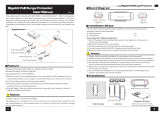
Figure 2: Features: System Components
3.3 Interface Ports
Ethernet Port
The Ethernet port (RJ-45 / F connector) receives DC power and provides Ethernet
connectivity with the local network. The Ethernet port connects to the PoE adapter using
a weatherproof CAT-5e Ethernet cable.
Note: The PoE does not amplify the Ethernet signal. The maximum total length of the
Ethernet cable is 91.5 m (300 ft). For example, 90 m (295 ft) from the RDL-3000 to the
PoE and 1.5 m (5 ft) from the PoE to the local network equipment.
GPS Antenna Port (RDL-3000-G)
The GPS antenna port (TNC / F connector) conducts RF signals between the RDL-3000
and the antenna system (ordered separately). This port is provided only on units factory-
equipped with GPS hardware. The GPS antenna can be located remotely from the RDL-
3000 unit by using up to 46 m (~150 ft) of high quality antenna cable. The GPS module
does not set the RDL-3000 internal date/time clock.
Figure 3: Features - RDL-3000-G with GPS Antenna, Sync, and Ethernet Ports

RDL-3000 INSTALLATION GUIDELINES
70-00159-01-06 Proprietary Redline Communications © 2012 Page 18 of 65 kune 12, 2012
A factory-installed protective weatherproof plastic cap is installed on the GPS antenna
port. If this cap is removed to install an antenna cable, the port must be weatherproofed.
Synchronization I/O Port (PPS)
The PPS port (TNC / F connector) is provided to synchronize the RF transmission cycles
of collocated sector controllers. This feature minimizes inter-sector interference by
synchronizing the transmit cycles of collocated RDL-3000 sector controllers.
This port is software configurable: mode = input, output, or disabled, impedance = 50
ohms, 75 ohms, or high impedance. Multiple RDL-3000 units can be synchronized by
using up to 46 m (~150 ft).of interconnecting synchronization cable.
Figure 4: Features - RDL-3000 with Sync Port and Ethernet Port
A factory-installed protective weatherproof plastic cap is installed on the PPS port. If this
cap is removed to install a synchronization cable or TNC tee connector, the port must be
weatherproofed.
RAS Smart Antenna Port (RDL-3000-M)
The RAS smart antenna is a multi-sector high-gain, fast switching, 360° directional beam
antenna for use with RDL-3000-M type subscribers or sector controllers. This is a factory
installed hardware option and operation is enabled by options key.
A factory-installed protective weatherproof plastic cap is installed on the RAS port. This
port must be weatherproofed when the control cable is installed.
Figure 5: Features - RDL-3000-M with Ethernet Port and RAS Antenna Control Port

RDL-3000 INSTALLATION GUIDELINES
70-00159-01-06 Proprietary Redline Communications © 2012 Page 19 of 65 kune 12, 2012
RF Ports
The two RF ports (N-type / F connectors) conduct RF signals between the RDL-3000
and the antenna system (ordered separately). The RDL-3000 can be operated using a
SISO (single antenna) or MIMO (multiple antenna) system.
Figure 6: Features - RF Ports (Top View of Radio)
IMPORTANT NOTICES
1. Both RF ports must always be electrically terminated to an antenna or other RF terminator
device when the RDL-3000 is powered-on.
2. When operating in SISO mode, the unused RF port must be electrically terminated.
3. Do not disconnect any RF cable while the RDL-3000 is powered-on.
Failure to follow these requirements may damage the RDL-3000 unit, requiring that the unit to
be returned for factory repair.
3.4 Configuration and Management
Use a standard Web browser or Telnet client to access all settings and statistics
necessary to configure and monitor the operation of the RDL-3000. The unit can also be
configured monitored using the SNMP-based Redline ClearView NMS.
ClearView NMS Application
The Redline Management Suite is a set of applications designed to assist provisioning,
monitoring and administration of the Redline components deployed in Radio Access
Networks (RANs). Contact your Redline representative or visit the Redline website for
further information about the Redline ClearView NMS application.
Telnet (CLI)
Use the following steps to monitor and configure the RDL-3000.
Using CLI, open a Telnet session to the unit IP address.
When the command prompt screen appears, login to the RDL-3000. The factory
default credentials are:
username: admin
password: admin
The Telnet session is logged out automatically when no commands are received (idle)
for a period of ten minutes. Use the following command to exit immediately from the CLI:
logout [ENTER]
The RDL-3000 supports two concurrent Telnet sessions. The first admin session opened
has full read/write capabilities. If a second concurrent session is opened, it has read-only
access.
Hint: When using a tool such as the Redline Monitoring Tool, login first as administrator
to enable full read/write capabilities and then start the monitoring tool (login is read only).

RDL-3000 INSTALLATION GUIDELINES
70-00159-01-06 Proprietary Redline Communications © 2012 Page 20 of 65 kune 12, 2012
Web Browser (HTTP)
To monitor and configure the RDL-3000 using HTTP, open a Web browser (Internet
Explorer 6 or higher recommended) and enter the unit IP address. For new systems, the
default IP address is 192.168.25.2. The following login dialog should be displayed:
Figure 7: Features - Web Login to the RDL-3000
The default username is 'admin' and the default password is 'admin'.
Note: There is no logout command on the Web interface.
Audible Alignment Tool
The audible alignment tool is provided to assist the installer to perform basic antenna
alignment. When enabled, the audible alignment signal 'chirps' slowly when a low signal
level is detected, and faster when stronger signals are detected. Use the Web or CLI
interface to enable and disable the tool.
3.5 Mounting Kits
Lightweight Mounting Kit
Lightweight mounting kit includes mounting bracket with assembly hardware. Fits 25-105
mm (1.0-4.25 in) mast pipe or mounts on a flat surface. Two 230 mm (9 in) RF jumper
cables (N-type connectors, 50 Ohm) are included with each mounting kit.
Heavy-Duty Mounting Kit
Heavy-duty mounting kit includes mounting bracket with assembly hardware. Fits 45-110
mm (1.75-4.5 in) mast. Two 400 mm (16 in) RF jumper cables (N-type connectors, 50
Ohm) are included with each mounting kit.
3.6 Grounding
Ground Lug
A ground-lug is provided on the RDL-3000 chassis. Use this connection to terminate
a grounding wire. All RDL-3000 systems must be properly grounded to protect against
power surges and accumulated static electricity.
/