Page is loading ...

Installation notes
DANLERS Limited, Vincients Road, CHIPPENHAM, Wiltshire, SN14 6NQ, UK.
Telephone: +44 (0)1249 443377 Fax: +44 (0)1249 443388
E-mail: [email protected] Web: www.danlers.co.uk
Company Registered Number 2570169 VAT Registration Number 543 5491 38
Products available from DANLERS
• PIRoccupancyswitches•Daylightlinkeddimmers•Manualhighfrequencydimmers
• Photocells • Radio remote controls • Time lag switches • Outdoor security switches
• Dimmers•Heating,ventilationandair-conditioningcontrols•Bespoke/O.E.M.products
Please call for more information or a free catalogue.
ThisproductconformstoBSEN60669-2-1andBSEN55015.
Pleaseensurethemostrecenteditionoftheappropriatelocalwiringregulationsareobserved
andsuitableprotectionisprovidede.g.a10ampcircuitbreakerandvoltagesurgeprotection.
Pleaseensurethatthisdeviceisdisconnectedfromthesupplyifaninsulationtestismade.
Thisproductiscoveredbyawarrantywhichextendsto5yearsfromthedateofmanufacture.
Precautions and Warranty
Twilight Switch
TWSW
DANLERSTWSWisIP66ratedandcanbesurfacemountedontoanexternal
wall.Itwillswitchalamploadonduringthehoursofdarkness.Thelightlevel
atwhichthelampwillswitchonandoffissetbyaluxadjuster.
Loading
The switch should only be connected to a 230V 50Hz AC supply. These
TWSW switches can switch up to:
6amps(1500W)ofresistiveloads.
6amps(1500W)ofuorescentloads.
3amps(750W)ofelectronicandwirewoundtransformerloads.
2amps(500W)ofCFL,2Dlamps,LEDDriversandLEDlampsandttings.
1amp(250W)offans
Minimumload2Wresistive,suitableformostenergysavinglamps,LEDs
andemergencyttings.
1. Pleasereadthesenotescarefullybeforecommencingwork.
Incaseofdoubtpleaseconsultaqualiedelectrician.
2. Theswitchshouldbesitedsuchthatitcanreceivemoredaylightthan
articiallight.Ensurethatanyarticiallightsarenottooclosetotheswitch
or shining into it.
3. Theswitchmustbemountedviathefourpre-formedholesonly,no
additional holes should be drilled through the enclosure.
4. Makesurethepowerisisolatedfromthecircuit.
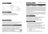
5. The detector should be connected as shown in diagram A.
SL Switched Line out.
L Livein
N Neutral in
6. IMPORTANT-Replaceterminalcover.
7. Oncethewiringhasbeencompletedandveried,switchonthesupply
and test the operation.
25/11/15 INS236 TWSW
Variants
Lowvoltagevariantscanbesupplied,codedbythefollowingsufxes:
• 12VAC 12V-(acsupply)operation
• 12VDC 12V-(dcsupply)operation
• 24VAC 24V-(acsupply)operation
• 24VDC 24V-(dcsupply)operation
Variantswithbespoketimingscanbemanufacturedtospecialorder.
Troubleshooting
Thelampswitchesoffabout30secondsafteritswitcheson.
• ToomucharticiallightisenteringtheTwilightswitch.
Thelampswitchesontooearlyintheevening.
• MovetheLuxadjusterfurthertowardsclockwise.
Thelampswitchesontoolateintheevening.
• Movetheluxadjusterfurtheranticlockwise.
The TWSW stops working.
• Ensuretheunitismountedcorrectlysothatnowatercanenter.
Installation procedure

Lux
adjustment
spindle
Photocell
SL L N N
Status LED
Terminal
block
Terminal
block
safety cap
Locate safety cap pins
in the hole ‘L’ and second
‘N’ holes above the
termination screws
L
load
optional manual
wall switch for
overriding off
N
230 VAC
SL
N
TWSW
The LUX is best set up when the ambient light is at approximately the
levelatwhichyouwishthelampstoswitchonat.
1.Beforepoweringup-unscrewTWSWlid.
2.TurnLuxadjustmentspindlefullyclockwise(10lux).
3.IMPORTANT:BeforepoweringuptheTWSW-covertheterminal
blockwiththesafetycapprovided.Thetwopinslocateintothe
terminal block moulding (see diagram E).
4.PowerupTWSW.ThestatusLEDshouldbeilluminated.Ifthe
statusLEDisnotilluminatedwhenthespindleisfullyclockwise
thentheambientlightlevelistoolowtoinhibittheluxswitch.To
remedythiseitherrepositiontheswitchorsettheswitchinglevel
whenmoreambientlightisavailable.
5.SlidetheTWSWlidoverthephotocell(lightcell)sothatonlythe
statusLEDandLuxadjustmentspindlearevisible(diagramC).
6.GraduallyturnthespindleanticlockwiseuntiltheLEDturnsOFF
ensuring you are not standing in a position that casts a shadow
acrossthefrontfaceoftheTWSW.
7.TheloadshouldswitchONafterapproximately30seconds.
8. Site the TWSW so that the LED is not re-illuminated when the load
isONie.seeingthelightingloaditiscontrolling.
A: Wiring diagram
LUX
max min
10 LUX300 LUX
D: Lux adjustment
C: Setting the Lux switching threshold
Lux
adjustment
spindle
Photocell
SL L N N
Status LED
Terminal
block
Terminal
block
safety cap
Locate safety cap pins
in the hole ‘L’ and second
‘N’ holes above the
termination screws
Locate safety cap plastic
pins in the hole ‘L’ and
second ‘N’ holes above
the termination screws.
Press firmly to attach.
B: TWSW layout
E: Safety cap
Lux set-up Diagrams
/


