
Henny Penny
Heated Holding Cabinet
Model HCH-930
Model HCH-932
Model HCH-930 CDT
Model HCH-932 CDT
OPERATOR’S MANUAL


Model HCH-930/932
FM05-022-F
Revised 11-17-10
LIMITED WARRANTY FOR HENNY PENNY EQUIPMENT
Subject to the following conditions, Henny Penny Corporation makes the following limited warranties to the original
purchaser only for Henny Penny appliances and replacement parts:
NEW EQUIPMENT: Any part of a new appliance, except baskets, lamps, and fuses, which proves to be defective in
material or workmanship within two (2) years from date of original installation, will be repaired or replaced without
charge F.O.B. factory, Eaton, Ohio, or F.O.B. authorized distributor. Baskets will be repaired or replaced for ninety (90)
days from date of original installation. Lamps and fuses are not covered under this Limited Warranty. To validate this
warranty, the registration card for the appliance must be mailed to Henny Penny within ten (10) days after installation.
FILTER SYSTEM: Failure of any parts within a fryer filter system caused by the use of the non-OEM filters or
other unapproved filters is not covered under this Limited Warranty.
REPLACEMENT PARTS: Any appliance replacement part, except lamps and fuses, which proves to be defective in
material or workmanship within ninety (90) days from date of original installation will be repaired or replaced without
charge F.O.B. factory, Eaton, Ohio, or F.O.B. authorized distributor.
The warranty for new equipment covers the repair or replacement of the defective part and includes labor charges and
maximum mileage charges of 200 miles round trip for a period of one (1) year from the date of original installation.
The warranty for replacement parts covers only the repair or replacement of the defective part and does not include any
labor charges for the removal and installation of any parts, travel, or other expenses incidental to the repair or replacement of
a part.
EXTENDED FRYPOT WARRANTY: Henny Penny will replace any frypot that fails due to manufacturing or workmanship
issues for a period of up to seven (7) years from date of manufacture. This warranty shall not cover any frypot that fails due to
any misuse or abuse, such as heating of the frypot without shortening.
0 TO 3 YEARS: During this time, any frypot that fails due to manufacturing or workmanship issues will
be replaced at no charge for parts, labor, or freight. Henny Penny will either install a new frypot at no cost or
provide a new or reconditioned replacement fryer at no cost.
3 TO 7 YEARS: During this time, any frypot that fails due to manufacturing or workmanship issues will
be replaced at no charge for the frypot only. Any freight charges and labor costs to install the new frypot as
well as the cost of any other parts replaced, such as insulation, thermal sensors, high limits, fittings, and
hardware, will be the responsibility of the owner.
Any claim must be presented to either Henny Penny or the distributor from whom the appliance was purchased. No
allowance will be granted for repairs made by anyone else without Henny Penny’s written consent. If damage occurs during
shipping, notify the sender at once so that a claim may be filed.
THE ABOVE LIMITED WARRANTY SETS FORTH THE SOLE REMEDY AGAINST HENNY PENNY FOR ANY BREACH
OF WARRANTY OR OTHER TERM. BUYER AGREES THAT NO OTHER REMEDY (INCLUDING CLAIMS FOR ANY INCI-
DENTAL OR CONSEQUENTIAL DAMAGES) SHALL BE AVAILABLE.
The above limited warranty does not apply (a) to damage resulting from accident, alteration, misuse, or abuse; (b) if the
equipment’s serial number is removed or defaced; or (c) for lamps and fuses. THE ABOVE LIMITED WARRANTY IS EX-
PRESSLY IN LIEU OF ALL OTHER WARRANTIES, EXPRESS OR IMPLIED, INCLUDING MERCHANTABILITY AND FIT-
NESS, AND ALL OTHER WARRANTIES ARE EXCLUDED. HENNY PENNY NEITHER ASSUMES NOR AUTHORIZES ANY
PERSON TO ASSUME FOR IT ANY OTHER OBLIGATION OR LIABILITY.
Revised 01/01/07

Model HCH-930/932
TABLE OF CONTENTS
Section Page
Section 1. INTRODUCTION .................................................................................................... 1-1
1-1. Heated Holding Cabinet ..................................................................................... 1-1
1-2. Features ............................................................................................................ 1-1
1-3. Proper Care ...................................................................................................... 1-1
1-4. Safety................................................................................................................ 1-2
1-5. Assistance ......................................................................................................... 1-2
Section 2. INSTALLATION....................................................................................................... 2-1
2-1. Introduction ....................................................................................................... 2-1
2-2. Unpacking ......................................................................................................... 2-1
2-3. Location ............................................................................................................ 2-2
2-4. Water Supply Connection .................................................................................. 2-2
2-5. Electrical Connection ......................................................................................... 2-2
2-6. Cabinet Dimensions ........................................................................................... 2-3
Section 3. OPERATION ............................................................................................................ 3-1
3-1. Introduction ....................................................................................................... 3-1
3-2. Operating Controls ............................................................................................ 3-1
3-3. Start-Up............................................................................................................ 3-4
3-4. Operation with Product...................................................................................... 3-4
3-5. Cleaning Procedures .......................................................................................... 3-5
3-6. Programming (HCH-930/932 CDT only) ........................................................... 3-6
3-7. Preventive Maintenance ..................................................................................... 3-9
3-8. Troubleshooting Guide ....................................................................................... 3-11
3-9 Error Codes ...................................................................................................... 3-12
GLOSSARY .............................................................................................................. G-1
Distributor Lists - Domestic and International
i 1110

Model HCH-930/932
1-1. HEATED HOLDING The Henny Penny Heated Holding Cabinets are used to keeps hot
CABINET foods at proper holding temperatures in commercial food service
operations.
As of August 16, 2005, the Waste Electrical and Electronic Equip-
ment directive went into effect for the European Union. Our
products have been evaluated to the WEEE directive. We have
also reviewed our products to determine if they comply with the
Restriction of Hazardous Substances directive (RoHS) and have
redesigned our products as needed in order to comply. To continue
compliance with these directives, this unit must not be disposed as
unsorted municipal waste. For proper disposal, please contact
your nearest Henny Penny distributor.
1-2. FEATURES • Electronically or adjustable, thermostatically controlled heat,
210
o
F (99
o
C) max
• Heat and humidity uniformly circulated throughout cabinet
• Fully insulated
• Removable drawers and baskets for easy cleaning
• Automatic water fill system
• Adjustable humidity level
• The CDT models have:
4 or 6 Programmable Timers
a. Set time from 1 to 99 minutes
b. Change timer during timing cycle
c. Continuous timing through power interruptions
Self diagnostic display for temperature, probe, and
programming failures
Ability to lock preset times and setpoint temperature
Easy front panel programming for times and
temperatures
1-3. PROPER CARE As in any unit of food service equipment, the Henny Penny Heated
Holding Cabinet does require care and maintenance. Requirements
for the maintenance and cleaning are contained in this manual and
must become a regular part of the operation of the unit at all times.
1110 1-1
SECTION 1. INTRODUCTION

Model HCH-930/932
1-4. SAFETY To ensure safe operation of the Henny Penny Heated Holding
Cabinet you need to fully understand the proper installation, opera-
tion, and maintenance procedures, which are found in this manual.
Where information is of importance or is safety related, the words
NOTICE, CAUTION, or WARNING are used. Their usage is
described below:
SAFETY ALERT SYMBOL is used with DANGER,
WARNING, or CAUTION which indicates a personal injury
type hazard.
NOTICE is used to highlight especially important information.
CAUTION used without the safety alert symbol indicates
a potentially hazardous situation which, if not avoided, may
result in property damage.
CAUTION indicates a potentially hazardous situation
which, if not avoided, may result in minor or moderate
injury.
The word WARNING is used to alert you to a procedure,
that if not performed properly, might cause personal
injury.
1-5. ASSISTANCE Should you require outside assistance, just call your local indepen-
dent Henny Penny distributor in your area, call Henny Penny Corp.
1-800-417-8405 toll free or 1-937-456-8405, or go to Henny Penny
online at www.hennypenny.com.
1-2 203

Model HCH-930/932
2-1. INTRODUCTION This section provides the installation and operation instructions for
the Henny Penny Heated Holding Cabinet.
Installation of this unit should be performed only by a qualified
service technician.
Do not puncture the skin of the unit with drills or
screws as component damage or electrical shock
could result.
2-2. UNPACKING The Henny Penny Heated Holding Cabinet has been inspected,
tested, and packed to ensure arrival in the best possible condition.
The cabinet is packed inside a triple wall carton with sufficient
packing material to withstand normal handling in shipment. The
carton is also strapped onto a wooden base.
Any shipping damages should be noted in the presence of the
delivery agent and signed prior to his or her departure.
To remove the cabinet from its carton:
1. Cut the bands holding the wooden base to the carton.
2. Lift the carton off the cabinet.
3. Remove unit from the wooden base.
4. Remove all packing material from around cabinet and
inside drawers.
5. Remove the top drawer and basket.
6. Remove the water pan by supporting it with one hand and
pulling the latches towards you, with the other hand. The water
pan drops down from the ceiling.
7. Install the four baffles in the slots in the water pan.
8. Reinstall the water pan by aligning the studs in the ceiling with
the holes in the water pan flanges, holding the pan flush against
the ceiling, and pushing the latches towards the rear of the
cabinet. Replace drawer and basket.
9. Peel off protective covering from exterior of cabinet.
Your heated holding cabinet is now ready to be located and
installed.
203 2-1
SECTION 2. INSTALLATION

Model HCH-930/932
2-3. LOCATION The unit should be placed on a table or shelf to allow easy access
for loading and unloading of product. For proper operation, the
cabinet must be level.
2-4. WATER SUPPLY The automatic water fill system requires a cold water supply.
CONNECTION The unit has a water strainer and fittings for connections to 1/4”
(6.35 mm) copper tubing. Run 1/4” (6.35 mm) copper tubing to
the cabinet, providing extra tubing to allow movement of the unit for
cleaning or maintenance. A water conditioner or filter is recom-
mended. Install a shut-off valve in the supply line.
Follow these steps when making the water supply connection:
1. Flush the incoming water line.
2. Insert the 1/4” (6.35 mm) copper tubing into the compression
nut and ferrule as far as it will go.
3. Tighten the nut with a 7/16” wrench.
Do not operate the unit without water connected to the
unit, or damage to components may result.
This unit as manufactured requires the installation of an appro-
priate back-siphoning device (as per National Plumbing Code
ASA-A40:8-1955) to be connected to the water inlet line.
This device to be connected in accordance with basic plumbing
code of the Building Officials and Code Administrators Interna-
tional, Inc. (BOCA), and the Food Service Sanitation Manual
of the Food and Drug Administration (FDA).
2-5. ELECTRICAL CONNECTION The heated holding cabinet is available from the factory as a
120 VAC, 50/60 Hz, 240 VAC, 50/60 Hz, or 230 VAC, 50 Hz,
single-phase unit. The data plate on the back of the unit specifies
the correct electrical supply. The unit requires a grounded recep-
tacle with a separate electrical line protected by a fuse or circuit
breaker of the proper rating.
To avoid electrical shock, the cabinet must be
adequately and safely grounded (earthed) according to
local electrical codes.
(FOR EQUIPMENT WITH CE MARK ONLY!)
To prevent electric shock hazard this appliance must be
bonded to other appliances or touchable metal surfaces
in close proximity to this appliance with an
equipotential bonding conductor. This appliance is
equipped with an equipotential lug for this purpose.
The equipotential lug is marked with the following
symbol
2-2 207
Model
Number Volts Watts Amps
HCH-930/932 120 842 7.3
HCH-930/932 240 842 3.5
HCH-930/932 230 770 3.3

Model HCH-930/932
21 1/16”
(53.5 cm)
2-6. CABINET DIMENSIONS
16 3/8”
(41.6 cm)
24 1/8” 18”
(61.3 cm) (45.7 cm)
24 1/8” 18”
(61.3 cm) (45.7 cm)
203 2-3


Model HCH-930/932
3-1. INTRODUCTION This section contains an explanation of all controls and components,
and information on operating the HCH-930 and HCH-932. Read
the Introduction, Installation and Operation Sections before operat-
ing the cabinet.
3-2. OPERATING CONTROLS Figures 3-1 through 3-10 identify and describe the function of all
operating controls and the major components of the cabinet.
Figure 3-1 Figure 3-2
Figure 3-3 Figure 3-4
1
2
3
4
5
803 3-1
SECTION 3. OPERATION

Model HCH-930/932
Figure 3-5 Figure 3-6
Figure 3-7 Figure 3-8
Figure 3-9
Figure 3-10
7
6
8
9
10
16
14 13 15 12 11
3-2 803
3-2. OPERATING CONTROLS (Continued)

Model HCH-930/932
Fig. Item
No. No. Description Function
3-1 1 Water Strainer A filter preventing particles from entering the water line
and blocking the water valve
3-2 2 Water Valve A valve, opened by the float switch, that allows water
to flow into the water pan
3-3 3 Water Pan Holds the water for creating humidity inside the cabinet
3-3 4 Baffles Metal plates placed in the water pan to transfer heat to
the water to create humidity
3-4 5 Float Switch An electromechanical level switch controlling the water
level in the water pan
3-5 6 Solid State Time Used to reduce the electrical load on the float switch
Delay Relay and provide an automatic delay of 10 seconds to avoid
overflowing the water pan
3-6 7 Blower Circulates air up from the cabinet, through the heater
coils, and water baffles, and back down into the
cabinet
3-7 8 Heater An 810 watt, open coil type heater
3-7 9 High Limit A safety device mounted on the heater plate which
protects the unit from overheating
3-8 10 Thermostat An electromechanical device controlling the
temperature inside the cabinet
3-9 11 Thermometer Indicates the temperature inside the cabinet
3-9 12 Power Switch Controls electrical current to the cabinet
3-9 13 Power Light When lit, indicates the power switch is on, and that the
components have electrical current supplied to them
3-9 14 Water Light When lit, indicates the float switch is calling for water
3-9 15 Heat Light When lit, indicates the thermostat is calling for heat
3-10 16 Fan Circulates fresh air around the operating components
203 3-3
3-2. OPERATING CONTROLS (Continued)

Model HCH-930/932
3-3. START-UP
Before using the heated holding cabinet, thoroughly clean
the unit as described in the Cleaning Procedures Section
of this manual.
For CDT units: To operate the unit, move the power switch to the ON position.
Select either the A or B mode by depressing the UP button
for A, or the DOWN button for B.
The display shows an increasing temperature indicating the cabinet
is heating. When the operating pre-set temperature is reached, the
display reads 74ºC + 3ºC (165ºF + 5ºF) in the A mode, or 85ºC +
3ºC (185ºF + 5ºF) in the B mode.
Place product inside the drawers, and press the appropriate
timer button.
For electromechanical units: Turn the power switch to the ON position to operate the cabinet.
The power light illuminates, indicating the unit is operating.
The water light illuminates, indicating water is flowing into the
water pan. When the pan is full, the light goes out and the water
stops flowing.
A 10 second delay occurs before the float switch activates
the water solenoid. This prevents overworking the compo-
nents if the cabinet is bumped, or moved.
The heat light illuminates, indicating the unit is heating. Once
operating temperature is reached, the light goes out. The operating
temperature is factory preset and is reached within one hour.
3-4. OPERATION WITH 1. Place hot product in the wire baskets, or pans, inside the
PRODUCT drawers.
2. Serve the product first, that has been in the cabinet the longest.
3. Open the drawers only as necessary to load and serve product.
3-4 1110

Model HCH-930/932
3-5. CLEANING PROCEDURES 1. Move the Power Switch to the OFF position.
2. Disconnect electrical supply to the unit.
To avoid burns, allow the unit to cool before cleaning.
3. Remove the wire baskets from the drawers.
4. Take the baskets to a sink and thoroughly clean.
5. Remove drawers by pulling them out and tilting them up.
6. Clean the drawers with a cloth and soapy water.
7. Remove the drip tray from the bottom of the cabinet and clean
it at a sink.
8. Clean the cabinet interior with a cloth and soapy water.
Do not use steel wool, other abrasive cleaners or
cleaners/sanitizers containing chlorine, bromine, iodine or
ammonia chemicals, as these will deteriorate the stainless
steel material and shorten the life of the unit.
DO NOT use a water jet (pressure sprayer) to clean the
unit, or component failure could result.
9. Wipe the cabinet exterior with a damp cloth. Avoid getting
water in the area of the control panel.
10. Replace the drip tray, drawers, and wire baskets.
11. If the unit is to remain turned off, leave the top drawer open two
or three inches to help dry the interior.
Step 5
Step 7
203 3-5
Step 3

Model HCH-930/932
3-6. PROGRAMMING Temperature Setting
(HCH-930/932 CDT Only) To change the setpoint temperature:
1. Press and hold the SET/TEMP button, and the setpoint
temperature is displayed.
2. While pressing the SET/TEMP button, press the UP
or DOWN button until the desired setpoint is displayed.
3. Release the SET/TEMP button to return to operating mode.
Before a temperature setting can be changed, the controls must
be unlocked. See Special Program Mode Section of this manual.
Timers Setting
To change the timers setting:
1. Make sure the timer is not running. (Display is dim.)
2. Press the timer button to be changed and the preset time shows
in the display.
3. While pressing the timer button, press the UP or DOWN
buttons until the desired time is displayed.
4. Once the desired time shows in the display, release both
buttons. The timer reverts back to the last mode of operation.
Before a timer setting can be changed, the controls must be
unlocked. See Special Program Mode Section of this
manual.
A timer can also be changed while it is in the countdown mode.
This is only in effect for the remainder of that timing cycle. At
the end of the timing cycle the timer reverts back to the previ-
ous time. To permanently change the timer, program it when the
timer display is dim.
3-6 1110

Model HCH-930/932
3-6. PROGRAMMING Timer Operation
(HCH-930/932 CDT Only) When the timer is not running, the timer display is dim. By
(Continued) pressing the timer button and starting a timing cycle, the time
remaining shows in the full brightness, and the decimal point in the
lower right corner blinks.
All timers operate independently of each other and may be started,
stopped, or aborted regardless of the status of the other timers. At
the end of the timing cycle an alarm sounds, “00” flashes in the timer
display, and the decimal point stops blinking. Press the timer to
reset.
Timing Through Power Down
If a power interruption, such as brown out, occurs, the control
checks the timers and cabinet temperature, once power is
restored. If the cabinet temperature drops more than
7ºC (10ºF) the timing cycle ends and the alarm sounds. This
informs the operator that this temperature drop may affect the
product.
If the cabinet temperature drops less than 7ºC (10ºF), the timers
continue timing from the point of the power interruption.
Special Program Mode
This special program mode consists of the following features:
1. Fahrenheit, “F” or Celsius, “C”.
2. Program Mode Lockout: Locked, “L” or unlocked, “U”.
3. One-button programming for times and temperature.
To enter the special program mode:
1. Turn the power switch to OFF.
2. Press and hold the SET/TEMP button while turning the
power switch to ON.
3. Release the SET/TEMP button. “F” or “C” displays in the
timer display, and “L” or “U” displays in timer 2 display.
1110 3-7

Model HCH-930/932
3-6. PROGRAMMING Celsius and Fahrenheit
(HCH-930/932 CDT Only) To change from Celsius (C), to Fahrenheit (F), or vice versa,
(Continued) enter the Special Program Mode, depress and release timer 1
button. This toggles the display from “C” to “F”, or “F” to “C”.
Turn unit off, then back on again to normal operation.
Locked or Unlocked Controls
The controls can be locked to prevent anyone from changing
the times and temperature. The timers and temperatures cannot
be changed until the controls are unlocked.
To unlock the controls, enter the Special Program Mode.
Then press and release timer 2 button. The display toggles
from “L” to “U”.
Turn unit off, then back on to normal operation.
Initialization of Control Board
The control can be reset to factory preset times and
temperatures.
To reset the controls, enter the Special Program Mode.
Press and release timer 3 button. The control reverts to factory
settings.
Turn unit off, then back on again to normal operation.
3-8 1110

Model HCH-930/932
3-7. PREVENTIVE Deliming Water Pan and Baffles
MAINTENANCE
Inspect the water pan and baffles every 10 days for lime buildup,
and clean when necessary.
Failure to keep the water pan and baffles free of lime
buildup reduces the performance of the cabinet.
1. Disconnect the electrical supply to the cabinet.
Failure to disconnect power to the cabinet causes the
interior of the cabinet to be “flooded” with water from
the automatic water fill system.
2. Remove the top drawer from the cabinet.
3. Remove the water pan and baffles by supporting the pan with one
and pulling out on the latches with the other hand. The water pan
drops down from the ceiling.
4. Remove the 4 baffles from the water pan.
Step 3
5. Clean the baffles and water pan with a brush, or other tool, to
loosen and remove any buildup. If the buildup is excessive, a
liquid chemical lime remover may help to remove lime.
Do not use steel wool, other abrasive cleaners or
cleaners/sanitizers containing chlorine, bromine, iodine or
ammonia chemicals, as these will deteriorate the stainless
steel material and shorten the life of the pan and baffles.
6. After removing all lime buildup, rinse pan and baffles, and place
water pan and baffles back into cabinet. Make sure water pan
is secure against the ceiling of the cabinet.
7. Replace the top drawer and reconnect electrical supply to unit.
1110 3-9

Model HCH-930/932
3-7. PREVENTIVE Clean Water Strainer
MAINTENANCE
(Continued) If the flow of water into the cabinet slows or stops, the water strainer
screen may be clogged. Follow the steps below to check and clean
the screen.
1. Shut off water supply.
2. Remove the hex cap at the bottom of the strainer.
3. Remove the screen from the strainer and clean it. If strainer has a
lime buildup, lime remover can be used.
4. Reassemble in reverse order.
5. Turn on water supply and check for leaks.
Step 2
3-10 1110
Page is loading ...
Page is loading ...
Page is loading ...
Page is loading ...
Page is loading ...
-
 1
1
-
 2
2
-
 3
3
-
 4
4
-
 5
5
-
 6
6
-
 7
7
-
 8
8
-
 9
9
-
 10
10
-
 11
11
-
 12
12
-
 13
13
-
 14
14
-
 15
15
-
 16
16
-
 17
17
-
 18
18
-
 19
19
-
 20
20
-
 21
21
-
 22
22
-
 23
23
-
 24
24
-
 25
25


Henny Penny HCH-932 Operating instructions
- Type
- Operating instructions
- This manual is also suitable for
Ask a question and I''ll find the answer in the document
Finding information in a document is now easier with AI
Related papers
-
Henny Penny HCH-930 Operating instructions
-
-
-
-
-
-
-
-
-
Other documents
-
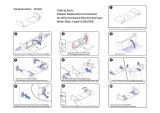 Laigoo LPM02 Installation guide
-
TECSUN R9702 Owner's manual
-
CARTER-HOFFMANN HWC10S1XE Operating instructions
-
Chromalox HCH User manual
-
Eaton 30R Operating instructions
-
-
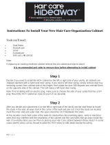 Hair Care Hideaway HCH1500 Installation guide
-
 GTS HCH-P7101-Retro Installation guide


