
De ll
™
Po werVault
™
LTO Tape User's Guide
User's Guide

Note!
Before using this information and the product it supports, be sure to read the general information under Notices in the Dell
PowerVault LTO Tape Drive User's Guide.
NOTE indicates important information that helps you make better use of your system.
NOTICE indicates either potential damage to hardware or loss of data and tells you how to avoid the problem.
CAUTION indicates a potential for property damage, personal injury, or death.
Information in this document is subject to change without notice.
© 2012 Dell Inc. All rights reserved.
© International Business Machines Corporation, 2012. All rights reserved.
Trademarks used in this text: Dell, the DELL logo, and PowerVault, are trademarks of Dell Inc. Microsoft and Windows
are registered trademarks of Microsoft Corporation.
Other trademarks and trade names may be used in this document to refer to either the entities claiming the marks
and names or their products. Dell Inc. disclaims any proprietary interest in trademarks and trade names other than
its own.
v Internal Drive Model Numbers: LTO Ultrium 6-H, LTO Ultrium 5-H, LTO Ultrium 4-H, LTO Ultrium 3-H
v External Drive Model Numbers: CSEH 001, LTO4-EH1, LTO3-EH1
v Rack Mount Model Number: 2U Storage Rack A
Initial release: November 2012

Contents
Figures ...............v
Tables ...............vii
Chapter 1. Introduction .......1-1
Overview ...............1-1
Encryption ..............1-2
Specifications and Features .........1-3
Tape Backup Software ..........1-4
Front Panel ..............1-4
Rear Panel ..............1-6
Chapter 2. Setting Up the Tape Drive 2-1
Pre-installed Internal Drives ........2-1
Installing Internal Drives .........2-1
Installing the Internal Drive - Step-By-Step
Instructions .............2-1
Installing External and Rack Mount Drives . . . 2-5
Installing the External Drive - Step-By-Step
Instructions .............2-5
Verifying Drive Operation ........2-7
Loading Device Drivers .........2-7
Ethernet Service Port Procedures ......2-8
Chapter 3. Using the Tape Drive . . . 3-1
Operating the Drive ...........3-1
Loading, Unloading, and Write-Protecting
Cartridges ..............3-2
Caring for Tape Cartridges .........3-5
Cleaning the Tape Mechanism ........3-7
Chapter 4. Using the Tape Backup
Software..............4-1
Chapter 5. Troubleshooting .....5-1
Obtaining Drivers and Firmware Upgrades . . . 5-1
Selecting a Diagnostic or Maintenance Function . . 5-1
General Guidelines ...........5-8
Methods of Receiving Errors and Messages . . . 5-9
Descriptions and Corrective Actions .....5-10
Drive Status .............5-13
Drive Maintenance ...........5-14
Fixing SAS Connectivity Problems ......5-15
Resolving Media-Related Problems ......5-16
Removing an Internal SAS Tape Drive .....5-16
TapeAlert ..............5-17
Recovering a Tape Cartridge ........5-20
Chapter 6. Specifications ......6-1
General Specifications...........6-1
Internal Drive .............6-1
External Drive .............6-2
Rack Mount Drive ............6-3
Chapter 7. Getting Help .......7-1
Technical Assistance ...........7-1
Dell Enterprise Training and Certification ....7-3
Problems with Your Order .........7-3
Product Information ...........7-3
Returning Items for Warranty Repair or Credit . . 7-3
Before You Call .............7-3
Chapter 8. Contacting Dell ......8-1
Appendix. Regulatory Information . . A-1
Glossary .............B-1
Index ...............X-1
iii

iv Dell PowerVault LTO Tape Drive User's Guide

Figures
1-1. PowerVault Internal Model ......1-1
1-2. PowerVault External Model ......1-2
1-3. PowerVault Rack Mount Model .....1-2
1-4. Front Panel............1-4
1-5. Rear Panel of Internal SAS Tape Drive 1-6
1-6. Rear Panel of External SAS Tape Drive 1-6
1-7. Rear Panel of the Rack Mount Tape Drive 1-7
2-1. Air Intake Area ..........2-2
2-2. Install the Drive ..........2-3
2-3. Mounting Holes on Tape Drive .....2-4
2-4. Attaching SAS Cable ........2-4
2-5. Secure the Drive ..........2-5
2-6. Connecting the SAS cable .......2-6
2-7. Connecting two SAS Hosts to one Tape
Drive..............2-7
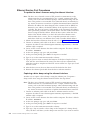
3-1. Turning on the External Drive .....3-1
3-2. Turning on the Rack Mount Drive 3-1
3-3. Resetting the Drive .........3-2
3-4. LTO Ultrium Data Cartridge ......3-3
3-5. Loading .............3-4
3-6. Setting the Write-Protect Switch .....3-5
5-1. Drive Status page .........5-14
5-2. Drive Status page - details ......5-14
5-3. Drive Maintenance page .......5-15
v

vi Dell PowerVault LTO Tape Drive User's Guide

Tables
1-1. LTO Generation Specifications .....1-3
1-2. SCD, Ready/Activity LED, and Fault LED
Descriptions ...........1-5
3-1. Supported Functions of Compatible Media
Types..............3-2
3-2. Environmental Specifications ......3-6
5-1. Diagnostic and Maintenance Function Codes
and Descriptions ..........5-2
5-2. General Troubleshooting .......5-8
5-3. Methods of Receiving Errors and Messages 5-10
5-4. Descriptions and Corrective Actions 5-10
5-5. TapeAlert Flags and Descriptions 5-17
6-1. General specifications ........6-1
6-2. Internal Drive specifications ......6-1
6-3. External Drive specifications ......6-3
6-4. Rack Mount drive specifications.....6-3
7-1. Diagnostics Checklist ........7-4
vii

viii Dell PowerVault LTO Tape Drive User's Guide

Chapter 1. Introduction
v “Overview”
– “Serial Attached SCSI (SAS) Interface” on page 1-2
v “Encryption” on page 1-2
v “Specifications and Features” on page 1-3
v “Tape Backup Software” on page 1-4
v “Front Panel” on page 1-4
v “Rear Panel” on page 1-6
Overview
The LTO PowerVault tape drive is a high-performance, high-capacity tape storage
device that is designed to back up and restore data and archive and retrieve files
in an Open Systems environment. The drive can be integrated into a system
(internal model) or can be provided as a separately packaged desktop unit
(external model). There are six generations of the Dell PowerVault tape drives in
the LTO series of products.
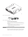
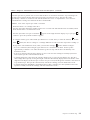
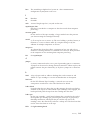
Figure 1-1 shows the internal model of the tape drive. Figure 1-2 on page 1-2
shows the separately purchased external model of the tape drive. Figure 1-3 on
page 1-2 shows the rack mount model.
a80hd004
Figure 1-1. PowerVault Internal Model
1-1

Serial Attached SCSI (SAS) Interface
A drive with a SAS (Serial Attached SCSI) interface can be linked directly to
controllers. The SAS interface offers the following advantages over the traditional
SCSI interface:
v SAS enables multiple devices (up to 128) of different sizes and types to be
connected simultaneously with thinner and longer cables.
v Its full-duplex signal transmission supports up to 6.0 Gb/s.
v SAS drives can be hot-plugged.
Encryption
The Tape Drive has Application Managed Encryption (AME) functionality. You
must have an application that supports encryption to use the drive's encryption
capability. For more details, consult your application support documentation.
a80hd00
1
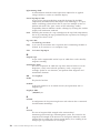
Figure 1-2. PowerVault External Model
a77ug279
Figure 1-3. PowerVault Rack Mount Model
1-2 Dell PowerVault LTO Tape Drive User's Guide

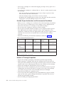
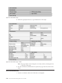
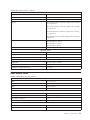
Specifications and Features
Specifications
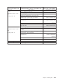
Table 1-1. LTO Generation Specifications
PowerVault Generation
Specification LTO6 LTO5-140 LTO4-120 LTO3-80
Native Capacity 2500 GB 1500 GB 800 GB 400 GB
2.5:1
Compressed
Capacity
6250 GB NA NA NA
2:1 Compressed
Capacity
5000 GB 3000 GB 1600 GB 800 GB
Maximum
Native Data
Transfer
160 MB/s 140 MB/s 120 MB/s 80 MB/s
Compressed
Maximum Data
Transfer*
400 MB/s 280 MB/s 240 MB/s 160 MB/s
Media
Partitioning**
X X NA NA
Data Safe
Mode**
X X NA NA
Encryption
Status LED
X X NA NA
* Assumes compression. The capacity and transfer rate you realize in practice
depends on the data set, which affects the actual compression ratio. LTO6 supports
2.5:1 compression. LTO5-140 and below support 2:1 compression.
** This feature must be supported by your tape backup software.
Features
The tape drive has the following features:
v Built-in read-after-write verification for a high level of data integrity
v Burst data transfer rate of 600 MB per second
v 512 MB of read/write cache memory
v Intelligent LTO-DC dual-mode compression algorithm
v Failsafe leader capture mechanism with pin pick error recovery
v Reads cartridge memory in LTO cartridges
v TapeAlert support for improved diagnostic and troubleshooting
v Two 6 Gb Serial Attached SCSI interface
v Speed matching (The drive can slow down to match the system data rate.)
v Sleep mode for energy conservation
v Backward read and write compatibility dependent on generation
v Compatible with all cartridges dependent on generation that bears the official
Ultrium LTO logo. See Table 1-1 for more information.
Chapter 1. Introduction 1-3

v Will interchange tapes with other LTO tape drives that bear the official Ultrium
LTO logo
v Support for WORM (Write Once Read Many) using WORM media
v Data encryption capability using LTO Ultrium 4, 5 and 6 media
v Ethernet interface for transferring drive firmware and dumps only (not an iSCSI
interface)
v Diagnostics of the drive over the ethernet service port (not an iSCSI interface)
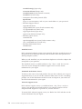
Tape Backup Software
You need backup software that supports the Dell PowerVault tape drive. As a
general rule, native backup applications (such as NTBackup and tar) do not
provide the required data streaming rate to get the full performance of your tape
drive. It is recommend that you use a backup application that provides better
memory management as well as other useful features, such as TapeAlert. For the
latest supported software versions, go to the Dell support website at
http://support.dell.com or visit the support site of your backup software vendor.
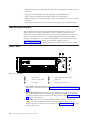
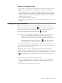
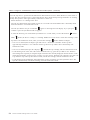
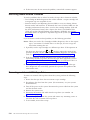
Front Panel
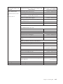
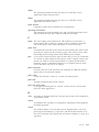
1 Eject button 4 Single-character display (SCD)
2 Ready/Activity LED 5 Single dot
3 Fault LED 6 Encryption Status LED
1. Eject button. The eject button enables you to perform several functions. These
functions are described in detail in Chapter 3, “Using the Tape Drive,” on page
3-1.
2. Ready/Activity LED. The front panel of your Dell PowerVault LTO tape drive
has a green Ready/Activity LED providing information about the state of the
tape drive. The LED can be solid on or flashing when lit. See Table 1-2 on page
1-5 for more descriptions.
3. Fault LED. The front panel of your Dell PowerVault LTO tape drive has an
amber fault LED indicating the drive has encountered an error, is not in a
normal operational status, or needs cleaning. See Table 1-2 on page 1-5 for more
detailed description.
a80hd00
3
1
3
4
6
2
5
Figure 1-4. Front Panel
1-4 Dell PowerVault LTO Tape Drive User's Guide

4. Single-character display (SCD). This LED presents a single-character code for
diagnostic/maintenance functions, error conditions, and informational
messages.
5. Single dot. This single-character display is blank during normal operation.
When a single dot illuminates and flashes on the display, the drive has created
a dump of vital technical data to drive memory.
6. Encryption status LED. This white LED indicates all data (except for the label
information) on the cartridge is encrypted. (LTO5 and LTO6 cartridges only).
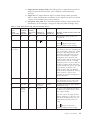
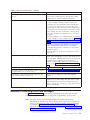
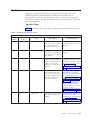
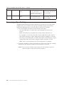
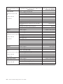
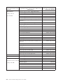
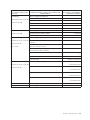
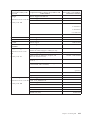
Table 1-2. SCD, Ready/Activity LED, and Fault LED Descriptions
Condition of
green
Ready/
Activity LED
Condition
of amber
Fault LED
Condition
of white
encryption
LED
Condition of
the SCD Panel
Condition of
the SCD Dot
Meaning of LEDs and SCD Panel and
SCD Dot
Off Off Off Off Off The tape drive has no power or is
powered off.
On Solid Off Off
Off or
C
Off The tape drive is powered on or (if a
solid
C
displays in the single
character display) needs cleaning.
Flashing once
per second
Off On or Off Off Off The tape drive is reading from the
tape, writing to the tape, rewinding the
tape, locating data on the tape, loading
the tape, or unloading the tape. The
Encryption LED will be On if all the
data on the cartridge is encrypted
during these drive operations. The
Ready/Activity LED also flashes green
if the tape drive contains a cartridge
during the power on cycle. In this case,
the drive completes POST and slowly
rewinds the tape (this process may take
approximately 13 minutes). The
Ready/Activity LED stops blinking
when the drive completes the recovery
and is ready for a read or write
operation. To eject the cartridge, press
the unload button.
Off On/Solid Off On Solid On/Off The tape drive is in maintenance mode
or is displaying an error code on the
SCD in maintenance mode option 9.
Off On Solid Off Flashing once
per second
On/Off Executing the selected option while in
maintenance mode.
Off Flashing
once per
second
Off On Solid Off An error occurred and the tape drive
or media may require service or drive
may require cleaning.
Note the code on the single character
display, and then go to the error code
table in the troubleshooting section to
determine the meaning of the error
codes.
If a
C
appears on the SCD, a
cleaning cartridge must be loaded.
Chapter 1. Introduction 1-5

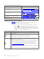
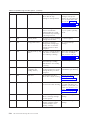
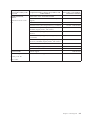
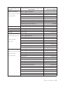
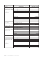
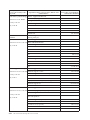
Table 1-2. SCD, Ready/Activity LED, and Fault LED Descriptions (continued)
Condition of
green
Ready/
Activity LED
Condition
of amber
Fault LED
Condition
of white
encryption
LED
Condition of
the SCD Panel
Condition of
the SCD Dot
Meaning of LEDs and SCD Panel and
SCD Dot
Off Flashing
twice per
second
Off Off Off The drive is updating firmware.
Off Flashing
once every
2 seconds
Off Off Off The drive detected an error and is
performing a firmware recovery. It will
reset automatically.
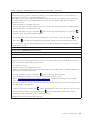
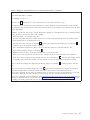
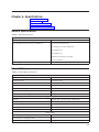
Rear Panel
1
2
3
4
a80hh095
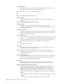
Figure 1-5. Rear Panel of Internal SAS Tape Drive
1 SAS connector 3 Library interface
2 Ethernet - not iSCSI - for
transferring firmware
and dumps only
4 LED controls for library drive sled
a80hh0
12
2
3
1
4
Figure 1-6. Rear Panel of External SAS Tape Drive
1 Power connector 3 SAS connectors
2 Fan enclosure 4 Ethernet - not iSCSI - for transferring
firmware and dumps only
1-6 Dell PowerVault LTO Tape Drive User's Guide

33
1
4
4
2
a80hh089
Figure 1-7. Rear Panel of the Rack Mount Tape Drive
1 Power connector 3 SAS connectors
2 Fan enclosure 4 Ethernet - not iSCSI - for transferring
firmware and dumps only
Chapter 1. Introduction 1-7

1-8 Dell PowerVault LTO Tape Drive User's Guide

Chapter 2. Setting Up the Tape Drive
v “Pre-installed Internal Drives”
v “Installing Internal Drives”
– “Installing the Internal Drive - Step-By-Step Instructions”
v “Installing External and Rack Mount Drives” on page 2-5
– “Installing the External Drive - Step-By-Step Instructions” on page 2-5
v “Verifying Drive Operation” on page 2-7
v “Loading Device Drivers” on page 2-7
v “Ethernet Service Port Procedures” on page 2-8
Pre-installed Internal Drives
Dell performs the installation and setup of internal tape drives that are shipped as
part of a system. If tape backup software is included in your system, refer to the
installation instructions included with the software.
For the latest supported software versions, go to the Dell support website
http://support.dell.com or visit the support site of your backup software vendor.
Installing Internal Drives
If your internal tape drive is not pre-installed, the installation instructions are
described in the following sections:
Installing the Drive — Prerequisites
The Dell PowerVault tape drive isa6GbSASdevice with a burst transfer rate of
600 MB per second. It is recommended that you use a dedicated SAS host bus
adapter for this tape drive.
Mounting Bay
You need one industry-standard, 5 1/4 inch, half-height bay in which to install the
PowerVault tape drive. The only supported mounting configurations are
horizontally with the base of the drive parallel to the ground, or vertically with
either the left or right side of the drive parallel to the ground.
Install and configure the drive according to the instructions provided in the Dell
documentation for your system.
Mounting Hardware
Most systems use trays or rails to mount the tape drive. If the mounting hardware
is pre-installed, you can simply slide the drive into the mounting bay. Some
systems do not use slides or rails and drives must be fixed in place with screws.
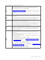
Installing the Internal Drive - Step-By-Step Instructions
Procedure
1. Unpacking the Drive
2-1

Unpack the tape drive and store the packaging. You may need the packaging if
you return the unit for service.
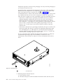
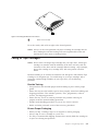
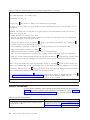
A period of time is required if the temperature of the drive when unpacked is
different than the temperature of its operating environment (measured at the
front of the bezel near the air intake area; see 1 in Figure 2-1). The
recommended time is 4 hours after the drive has been unpacked or 1 hour after
any condensation that you can see has evaporated, whichever is greater. To
allow the drive to adjust to its new environment, apply the following measures:
v If the drive is colder than its operating environment and the air contains
sufficient humidity, condensation may occur in the drive and damage it.
When the drive has warmed to the operating temperature range (greater
than 10 degrees C or 50 degrees F) and no danger of condensation is present
(the air is dry), warm the drive more quickly by powering it on for 30
minutes. Use a scratch tape to test the drive before inserting a tape that
contains data.
v If the drive is hotter than its operating environment, the tape can stick to the
drive head. When the drive has cooled to the operating temperature range
(less than 40 degrees C or 104 degrees F), cool the drive more quickly by
applying airflow for 30 minutes. Power on the drive and use a scratch tape
to test it before inserting a tape that contains data.
If you are uncertain about whether the temperature of the drive is within the
recommended operating range or the humidity is sufficient to cause
condensation, allow the drive to adjust to its new environment for the full 4
hours.
1 Air Intake Area
2. Removing Power from the System
a. Power-off the system.
b. Disconnect the power cord from both the electrical outlet and the system.
a80hd002
1
Figure 2-1. Air Intake Area
2-2 Dell PowerVault LTO Tape Drive User's Guide

3. Preparing the Mounting Bay in Your System
CAUTION:
To avoid personal injury or damage to the system or tape drive, ensure that
the system power cord is disconnected before you install the drive.
Refer to your system's documentation for instructions on how to prepare the
mounting bay to receive the tape drive.
4. Attaching Mounting Hardware
If your system requires special rails or other hardware to install the tape drive,
mount them on the tape drive in this step.
If your system does not require special mounting hardware, proceed to step 5.
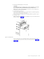
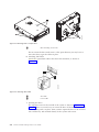
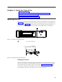
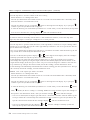
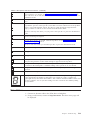
5. Installing the Drive
Slide the tape drive into the open bay, aligning the tray or rails with the slots in
the bay, as shown in Figure 2-2.
If your system does not use mounting hardware, check that the holes in the
chassis are aligned with the holes in the side of the tape drive (see Figure 2-3
on page 2-4).
a80hd00
6
Figure 2-2. Install the Drive
Chapter 2. Setting Up the Tape Drive 2-3

1 M-3 mounting screw holes
Do not secure the drive with screws at this point because you may have to
move the drive to get the cables in place.
6. Attaching SAS Cable
Attach the system SAS cable to the drive SAS connector, as shown in
Figure 2-4.
1 SAS cable
2 Power cable
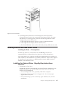
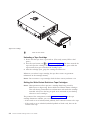
7. Securing the Drive
The tape drive can now be secured to the system as shown in Figure 2-5 on
page 2-5. There are several ways to secure the drive. If the drive is on rails or
in a sled, then push it in place. Some systems require the drive to be inserted
into a media bay and attached directly to the system with screws.
1
a80hh0
10
1
1
Figure 2-3. Mounting Holes on Tape Drive
a80hh094
1
2
Figure 2-4. Attaching SAS Cable
2-4 Dell PowerVault LTO Tape Drive User's Guide
Page is loading ...
Page is loading ...
Page is loading ...
Page is loading ...
Page is loading ...
Page is loading ...
Page is loading ...
Page is loading ...
Page is loading ...
Page is loading ...
Page is loading ...
Page is loading ...
Page is loading ...
Page is loading ...
Page is loading ...
Page is loading ...
Page is loading ...
Page is loading ...
Page is loading ...
Page is loading ...
Page is loading ...
Page is loading ...
Page is loading ...
Page is loading ...
Page is loading ...
Page is loading ...
Page is loading ...
Page is loading ...
Page is loading ...
Page is loading ...
Page is loading ...
Page is loading ...
Page is loading ...
Page is loading ...
Page is loading ...
Page is loading ...
Page is loading ...
Page is loading ...
Page is loading ...
Page is loading ...
Page is loading ...
Page is loading ...
Page is loading ...
Page is loading ...
Page is loading ...
Page is loading ...
Page is loading ...
Page is loading ...
Page is loading ...
Page is loading ...
Page is loading ...
Page is loading ...
Page is loading ...
Page is loading ...
Page is loading ...
Page is loading ...
Page is loading ...
Page is loading ...
Page is loading ...
Page is loading ...
Page is loading ...
Page is loading ...
Page is loading ...
Page is loading ...
Page is loading ...
Page is loading ...
Page is loading ...
Page is loading ...
Page is loading ...
Page is loading ...
Page is loading ...
Page is loading ...
Page is loading ...
-
 1
1
-
 2
2
-
 3
3
-
 4
4
-
 5
5
-
 6
6
-
 7
7
-
 8
8
-
 9
9
-
 10
10
-
 11
11
-
 12
12
-
 13
13
-
 14
14
-
 15
15
-
 16
16
-
 17
17
-
 18
18
-
 19
19
-
 20
20
-
 21
21
-
 22
22
-
 23
23
-
 24
24
-
 25
25
-
 26
26
-
 27
27
-
 28
28
-
 29
29
-
 30
30
-
 31
31
-
 32
32
-
 33
33
-
 34
34
-
 35
35
-
 36
36
-
 37
37
-
 38
38
-
 39
39
-
 40
40
-
 41
41
-
 42
42
-
 43
43
-
 44
44
-
 45
45
-
 46
46
-
 47
47
-
 48
48
-
 49
49
-
 50
50
-
 51
51
-
 52
52
-
 53
53
-
 54
54
-
 55
55
-
 56
56
-
 57
57
-
 58
58
-
 59
59
-
 60
60
-
 61
61
-
 62
62
-
 63
63
-
 64
64
-
 65
65
-
 66
66
-
 67
67
-
 68
68
-
 69
69
-
 70
70
-
 71
71
-
 72
72
-
 73
73
-
 74
74
-
 75
75
-
 76
76
-
 77
77
-
 78
78
-
 79
79
-
 80
80
-
 81
81
-
 82
82
-
 83
83
-
 84
84
-
 85
85
-
 86
86
-
 87
87
-
 88
88
-
 89
89
-
 90
90
-
 91
91
-
 92
92
-
 93
93


Ask a question and I''ll find the answer in the document
Finding information in a document is now easier with AI
Related papers
-
Dell PowerVault LTO7 User guide
-
Dell Latitude D500 User guide
-
-
-
-
-
-
-
Dell TL1000 User guide
-
Dell PowerVault TL2000 User guide