Spectracom 8197 GPS Ageless Master Oscillator User manual
- Category
- Smoke detectors
- Type
- User manual
This manual is also suitable for

MODEL 8197
GPS AGELESS MASTER OSCILLATOR
INSTRUCTION MANUAL
SPECTRACOM CORPORATION
95 Methodist Hill Drive, Suite 500
Rochester, NY 14623
PHONE 585-321-5800
FAX 585-321-5219
REVISIONS, IF ANY, ARE LOCATED AT THE END OF THE MANUAL
MANUAL REVISION A
December 2003

5-Year Warranty
SPECTRACOM 95 Methodist Hill Drive Suite 500 Rochester, NY 14623
+1.585.321.5800 FAX: +1.585.321.5218 www.spectracomcorp.com sales@spectracomcorp.com
LIMITED WARRANTY________________________________
Spectracom warrants each new product manufactured and sold by
it to be free from defects in material, workmanship, and
construction, except for batteries, fuses, or other material normally
consumed in operation that may be contained therein, for five
years after shipment to the original purchaser (which period is
referred to as the "warranty period"). This warranty shall not
apply if the product is used contrary to the instructions in its
manual or is otherwise subjected to misuse, abnormal operations,
accident, lightning or transient surge, repairs or modifications not
performed by Spectracom.
The GPS receiver is warranted for one year from date of shipment
and subject to the exceptions listed above. The power adaptor, if
supplied, is warranted for one year from date of shipment and
subject to the exceptions listed above.
The Rubidium oscillator, if supplied, is warranted for two years
from date of shipment and subject to the exceptions listed above.
All other items and pieces of equipment not specified above,
including the antenna unit, antenna surge suppressor and antenna
pre-amplifier are warranted for 5 years, subject to the exceptions
listed above.
WARRANTY CLAIMS________________________________
Spectracom's obligation under this warranty is limited to in-factory
service and repair, at Spectracom's option, of the product or the
component thereof, which is found to be defective. If in
Spectracom's judgment the defective condition in a Spectracom
product is for a cause listed above for which Spectracom is not
responsible, Spectracom will make the repairs or replacement of
components and charge its then current price, which buyer agrees
to pay.
Spectracom shall not have any warranty obligations if the
procedure for warranty claims is not followed. Users must notify
Spectracom of the claim with full information as to the claimed
defect. Spectracom products shall not be returned unless a return
authorization number is issued by Spectracom. Spectracom
products must be returned with the description of the claimed
defect and identification of the individual to be contacted if
additional information is needed. Spectracom products must be
returned properly packed with transportation charges prepaid.
EXCEPT FOR THE LIMITED WARRANTY STATED ABOVE,
SPECTRACOM DISCLAIMS ALL WARRANTIES OF ANY KIND
WITH REGARD TO SPECTRACOM PRODUCTS OR OTHER
MATERIALS PROVIDED BY SPECTRACOM, INCLUDING
WITHOUT LIMITATION ANY IMPLIED WARRANTY OR
MERCHANTABILITY OR FITNESS FOR A PARTICULAR PURPOSE.
Spectracom shall have no liability or responsibility to the original
customer or any other party with respect to any liability, loss, or
damage caused directly or indirectly by an Spectracom product,
material, or software sold or provided by Spectracom,
replacement parts or units, or services provided, including but not
limited to any interruption of service, excess charges resulting from
malfunctions of hardware or software, loss of business or
anticipatory profits resulting from the use or operation of the
Spectracom product or software, whatsoever or howsoever
caused. In no event shall Spectracom be liable for any direct,
indirect, special or consequential damages whether the claims are
grounded in contract, tort (including negligence), or strict liability.
EXTENDED WARRANTY COVERAGE___________________
Extended warranties can be purchased for additional periods
beyond the standard five-year warranty. Contact Spectracom no
later than the last year of the standard five-year warranty for
extended coverage.

TABLE OF CONTENTS
SECTION 1 GENERAL INFORMATION
1.0 INTRODUCTION ....................................................................................................................1-1
1.1 FEATURES ............................................................................................................................1-2
1.2 WARRANTY INFORMATION AND PRODUCT SUPPORT.................................................. 1-2
1.3 MANUAL ERRATA AND SPECIAL DOCUMENTATION ..................................................... 1-3
1.4 UNPACKING.......................................................................................................................... 1-3
1.5 SPECIFICATIONS .................................................................................................................1-4
1.5.1 Receiver ....................................................................................................................1-4
1.5.2 Standard Frequency Outputs ....................................................................................1-4
1.5.3 Frequency Standard Stability ....................................................................................1-5
1.5.4 1 PPS Output.............................................................................................................1-5
1.5.5 1544 kHz Timing Outputs..........................................................................................1-6
1.5.6 2048 kHz Timing Outputs..........................................................................................1-6
1.5.7 Data Clock Timing Outputs .......................................................................................1-7
1.5.8 Data Sync Timing Outputs ........................................................................................1-7
1.5.9 Indicator Lamps .........................................................................................................1-8
1.5.10 Alarms .......................................................................................................................1-8
1.5.10.1 Alarms Classifications .................................................................................1-9
1.5.10.2 Tracking Alarm Classifications .................................................................1-10
1.5.10.3 Alarm Interface ......................................................................................... 1-10
1.5.11 Communication Ports .............................................................................................. 1-11
1.5.11.1 RS-232 Com.............................................................................................. 1-11
1.5.11.2 RS-485 Com.............................................................................................. 1-11
1.5.12 Input Power .............................................................................................................1-12
1.5.13 Mechanical ..............................................................................................................1-12
1.5.14 Environmental..........................................................................................................1-13
1.5.15 Model 8225 GPS Antenna Specifications ...............................................................1-13
1.5.15.1 Electrical Specifications............................................................................. 1-13
1.5.15.2 Mechanical Specifications .........................................................................1-13
1.5.16 Model 8226 Impulse Suppressor.............................................................................1-13
1.5.17 Model 8227 Inline Amplifier ..................................................................................... 1-14
SECTION 2 INSTALLATION
2.0 INTRODUCTION ....................................................................................................................2-1
2.1 MODEL 8225 GPS ANTENNA ..............................................................................................2-1
2.1.1 Antenna Installation ...................................................................................................2-1
2.2 ANTENNA CABLE..................................................................................................................2-2
2.2.1 Cable Lengths ...........................................................................................................2-3
2.3 MODEL 8226 IMPULSE SUPPRESSOR .............................................................................. 2-3
2.4 MODEL 8227 GPS INLINE AMPLIFIER................................................................................ 2-4
2.5 MODEL 8197 PREPARATION FOR USE ............................................................................. 2-6
2.5.1 Antenna Connection.................................................................................................. 2-6
2.5.2 AC Power ..................................................................................................................2-6
2.5.3 DC Power ..................................................................................................................2-6
2.5.4 Chassis Ground.........................................................................................................2-7
2.6 INITIAL OPERATION............................................................................................................. 2-7
2.7 QUALIFYING THE INSTALLATION...................................................................................... 2-8
2.7.1 GPS Signal Status .................................................................................................... 2-8
2.7.2 Tracking Histogram .................................................................................................2-10
2.8 RECEPTION TROUBLESHOOTING................................................................................... 2-11
2.8.1 No Reception .........................................................................................................2-11
2.8.2 Low GPS Quality .....................................................................................................2-12
2.9 FACTORY CONFIGURATION............................................................................................. 2-12

SECTION 3 OPERATION
3.0 INTRODUCTION ....................................................................................................................3-1
3.1 FRONT PANEL FUNCTIONS................................................................................................ 3-1
3.1.1 Status Lamps.............................................................................................................3-1
3.1.1.1 Power .........................................................................................................3-1
3.1.1.2 Tracking GPS ............................................................................................. 3-1
3.1.1.3 Oscillator Locked .......................................................................................3-1
3.1.2 Alarm Lamps .............................................................................................................3-1
3.1.2.1 Major Alarm Lamp ......................................................................................3-2
3.1.2.2 Minor Alarm Lamp ......................................................................................3-2
3.1.3 Battery Lamps (Option 02 only)..................................................................................3-4
3.1.3.1 Ready Lamp................................................................................................ 3-4
3.1.3.2 Charging Lamp ...........................................................................................3-4
3.1.3.3 Replace Lamp.............................................................................................3-4
3.1.4 RS-232 Com..............................................................................................................3-5
3.1.5 10-MHz Output ..........................................................................................................3-6
3.1.6 1PPS Output..............................................................................................................3-6
3.2 REAR PANEL FUNCTIONS .................................................................................................. 3-6
3.2.1 GPS Antenna.............................................................................................................3-6
3.2.2 Frequency Outputs ....................................................................................................3-6
3.2.2.1 Signature Control........................................................................................3-6
3.2.2.2 Output Options ........................................................................................... 3-8
3.2.3 1544 kHz and 2048 kHz Timing Outputs .................................................................3-8
3.2.3.1 RS-485 Outputs ..........................................................................................3-9
3.2.3.2 Major Alarm Contacts ...............................................................................3-10
3.2.4 Data Clock Timing Outputs .....................................................................................3-10
3.2.4.1 RS-485 Outputs ........................................................................................3-11
3.2.4.2 Major Alarm Relay ....................................................................................3-12
3.2.5 Set Up Switches ......................................................................................................3-12
3.2.5.1 RS-485 Address .......................................................................................3-12
3.2.5.2 RS-485 Baud Rate....................................................................................3-13
3.2.5.3 Spares.......................................................................................................3-13
3.2.5.4 Termination ...............................................................................................3-13
3.2.6 RS-485 COM ...........................................................................................................3-14
3.2.7 Data Sync Timing Outputs ......................................................................................3-15
3.2.7.1 RS-485 Outputs ........................................................................................3-17
3.2.7.2 Major Alarm Contacts ...............................................................................3-17
3.2.8 Alarm Outputs..........................................................................................................3-18
3.2.9 DC Power ................................................................................................................3-19
3.2.10 AC Power ................................................................................................................3-20
3.2.11 Cooling Fan .............................................................................................................3-21
3.2.12 Chassis Ground.......................................................................................................3-21
3.2.13 Battery Disconnect Switch.......................................................................................3-21

SECTION 4 SOFTWARE COMMANDS
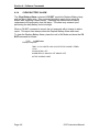
4.0 INTRODUCTION ....................................................................................................................4-1
4.1 RS-232 COMMANDS............................................................................................................. 4-1
4.2 RS-232 COMMAND DESCRIPTIONS ...................................................................................4-2
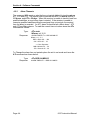
4.2.1 ANTENNA CABLE DELAY........................................................................................ 4-3
4.2.2 ALARM TIMEOUTS................................................................................................... 4-4
4.2.3 CLEAR ALARM ......................................................................................................... 4-5
4.2.4 CLEAR BATTERY ALARM .......................................................................................4-6
4.2.5 CONFIGURATION .................................................................................................... 4-7
4.2.6 DISPLAY ALARM LOG ............................................................................................. 4-8
4.2.7 DATE .........................................................................................................................4-9
4.2.8 DISPLAY FREQUENCY MEASUREMENT ............................................................4-10
4.2.9 DISPLAY OSCILLATOR LOG.................................................................................4-11
4.2.10 DISPLAY TRACKING HISTOGRAM.......................................................................4-13
4.2.11 EVENT OUTPUT.....................................................................................................4-15
4.2.12 GPS SIGNAL STATUS............................................................................................4-16
4.2.13 HELP .......................................................................................................................4-18
4.2.14 LOCATION ..............................................................................................................4-19
4.2.15 SIGNATURE CONTROL.........................................................................................4-20
4.2.16 SET MODE..............................................................................................................4-21
4.2.17 STATUS INFORMATION ........................................................................................ 4-22
4.2.18 TIME ........................................................................................................................4-23
4.2.19 TEST MODE............................................................................................................4-24
4.2.20 TIME ZONE OFFSET..............................................................................................4-25
4.2.21 UTC TO GPS TIME .................................................................................................4-26
4.2.22 VERSION ................................................................................................................4-27
4.2.23 1PPS OFFSET ........................................................................................................4-28
4.3 RS-485 COMMAND STRUCTURE.....................................................................................4-29
4.4 RS-485 COMMAND DESCRIPTIONS .................................................................................4-30
4.4.1 ANTENNA CABLE DELAY...................................................................................... 4-30
4.4.2 ALARM EVENT HISTORY ......................................................................................4-31
4.4.3 ALARM STATUS .....................................................................................................4-31
4.4.4 ALARM TIMEOUTS................................................................................................. 4-31
4.4.5 CLEAR ALARM HISTORY ...................................................................................... 4-31
4.4.6 GPS SIGNAL STATUS............................................................................................4-32
4.4.7 LOCATION ..............................................................................................................4-33
4.4.8 SIGNAL SELECTION ..............................................................................................4-33
4.4.9 SHORT STATUS..................................................................................................... 4-33
4.4.10 TIME AND DATE..................................................................................................... 4-34
4.4.11 TIME ZONE OFFSET..............................................................................................4-34
4.4.12 WHO........................................................................................................................4-34
4.4.13 1PPS OFFSET ........................................................................................................ 4-34

SECTION 5 OPTIONS AND ACCESSORIES
5.0 INTRODUCTION ....................................................................................................................5-1
5.1 OPTION 02 INTERNAL BATTERY BACKUP....................................................................... 5-2
5.1.1 Battery Lamps ...........................................................................................................5-2
5.1.2 Option 02 Specifications............................................................................................ 5-3
5.2 OPTION 03 BUILT IN DISTRIBUTION AMPLIFIER .............................................................5-3
5.2.1 System Components .................................................................................................5-3
5.2.1.1 Model 8140T Line Taps...........................................................................5-3
5.2.1.2 Model 8140VT VersaTap Frequency Synthesizer .................................. 5-4
5.2.1.3 Model 8140TA Line Extender Amplifier................................................... 5-4
5.2.1.4 Model 8140MT MultiTap..........................................................................5-5
5.2.2 Design of Distribution Networks ................................................................................ 5-6
5.3 OPTION 06 - 12.8-MHZ OUTPUTS ....................................................................................... 5-8
5.4 OPTION 07 - 5-MHZ OUTPUTS ............................................................................................ 5-9
5.5 OPTION 08 - 1-MHZ OUTPUTS ............................................................................................5-9
5.6 OPTION 11 - RACK MOUNT SLIDES.................................................................................. 5-9
5.7 OPTION 14 - CTCSS OUTPUTS ........................................................................................5-10
5.7.1 Data Sync Timing Outputs ......................................................................................5-10
5.7.2 Data Sync Alarm Contacts ......................................................................................5-12
5.7.3 RS-485 Timing Signals............................................................................................ 5-13
5.7.4 CTCSS Configuration.............................................................................................. 5-13
SECTION 6 SERVICE INFORMATION
6.0 INTRODUCTION ....................................................................................................................6-1
6.1 BATTERY REPLACEMENT .................................................................................................. 6-1
6.1.1 Battery Replacement Instructions .............................................................................6-1

TABLES
TABLE 1-1 MODEL 8197 ANCILLARY KITS .....................................................................................1-3
TABLE 2-1 DC POWER CONFIGURATIONS ...................................................................................2-6
TABLE 2-2 TYPICAL ANTENNA CABLE RESISTANCE VALUES..................................................2-11
TABLE 2-3 DEFAULT SETTINGS....................................................................................................2-13
TABLE 3-1 RS-232 COMM PIN ASSIGNMENTS ..............................................................................3-5
TABLE 3-2 TIMING OUTPUT PIN ASSIGNMENTS ..........................................................................3-9
TABLE 3-3 DATA CLOCK PIN ASSIGNMENTS..............................................................................3-11
TABLE 3-4 ADDRESS SELECTION ................................................................................................3-13
TABLE 3-5 RS-485 COM PIN ASSIGNMENTS ...............................................................................3-14
TABLE 3-6 DATA SYNC PIN ASSIGNMENTS ................................................................................3-16
TABLE 3-7 ALARM OPERATION ....................................................................................................3-19
TABLE 3-8 DC POWER CONFIGURATIONS .................................................................................3-19
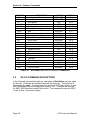
TABLE 4-1 ALPHABETICAL LIST OF RS-232 COMMANDS............................................................4-2
TABLE 4-2 COMMON OFFSET VALUES........................................................................................4-25
TABLE 4-3 RS-485 COMMAND PROTOCOL .................................................................................4-29
TABLE 4-4 ALPHABETICAL LIST OF RS-485 COMMANDS..........................................................4-30
TABLE 5-1 LINE TAP LOADS............................................................................................................5-6
TABLE 5-2 OPTION 11 CHECKLIST .................................................................................................5-9
TABLE 5-3 OPTION 14 DATA SYNC PIN ASSIGNMENTS ............................................................5-11
TABLE 5-4 CTCSS #1 AND CTCSS #2 FREQUENCY LIST...........................................................5-12
TABLE 5-5 CTCSS TONE LIST .......................................................................................................5-14

ILLUSTRATIONS
FIGURE 1-1 MODEL 8197 AGELESS MASTER OSCILLATOR ......................................................... 1-1
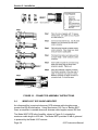
FIGURE 2-1 ANTENNA INSTALLATION ............................................................................................. 2-2
FIGURE 2-2 MODEL 8226 IMPULSE SUPPRESSOR ........................................................................2-3
FIGURE 2-3 CONNECTOR ASSEMBLY INSTRUCTIONS .................................................................2-4
FIGURE 2-4 MODEL 8227 INLINE AMPLIFIER................................................................................... 2-5
FIGURE 2-5 CABLE GUIDELINES ......................................................................................................2-5
FIGURE 2-6 DC POWER CONNECTOR............................................................................................. 2-7
FIGURE 3-1 MODEL 8197 FRONT PANEL .........................................................................................3-3
FIGURE 3-2 RS-232 COM PIN NUMBERING ..................................................................................... 3-5
FIGURE 3-3 MODEL 8197 REAR PANEL ...........................................................................................3-7
FIGURE 3-4 TIMING OUTPUT CONNECTOR ....................................................................................3-8
FIGURE 3-5 RS-485 OUTPUT .............................................................................................................3-9
FIGURE 3-6 SINGLE-ENDED CONNECTION...................................................................................3-10
FIGURE 3-7 DATA CLOCK CONNECTOR........................................................................................3-10
FIGURE 3-8 RS-485 LINE DRIVER ...................................................................................................3-12
FIGURE 3-9 COM CONNECTOR ......................................................................................................3-14
FIGURE 3-10 RS-485 CONNECTION..................................................................................................3-15
FIGURE 3-11 DATA SYNC CONNECTOR ..........................................................................................3-15
FIGURE 3-12 DATA SYNC DRIVERS .................................................................................................3-17
FIGURE 3-13 ALARM OUTPUTS TERMINAL BLOCK........................................................................3-18
FIGURE 3-14 DC POWER CONNECTOR........................................................................................... 3-20
FIGURE 3-15 AC POWER MODULE ...................................................................................................3-21
FIGURE 4-1 COMMAND STRUCTURE...............................................................................................4-1
FIGURE 5-1 LINE TAP NUMBER AND DISTANCE CHART - OPTION 03......................................... 5-7
FIGURE 5-2 TYPICAL INTERCONNECTION DIAGRAM....................................................................5-8
FIGURE 5-3 SLIDES, OPTION 11 .....................................................................................................5-10
FIGURE 5-4 DATA SYNC CONNECTOR ..........................................................................................5-11
FIGURE 5-5 DATA SYNC DRIVERS .................................................................................................5-13

MODEL 8197
SECTION 1
GENERAL INFORMATION
1.0 INTRODUCTION
1.1 FEATURES
1.2 WARRANTY INFORMATION AND PRODUCT SUPPORT
1.3 MANUAL ERRATA AND SPECIAL DOCUMENTATION
1.4 UNPACKING
1.5 SPECIFICATIONS

Page 1-1 8197 Instruction Manual
GENERAL INFORMATION
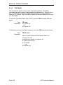
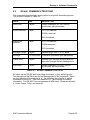
1.0 INTRODUCTION
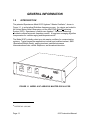
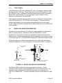
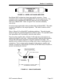
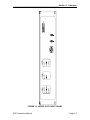
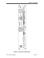
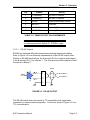
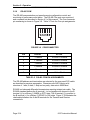
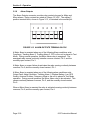
The patented Spectracom Model 8197 Ageless Master Oscillator*, shown in
Figure 1-1, is a disciplined Rubidium frequency source. Its outputs are locked to
the United States Naval Observatory via the NAVSTAR Global Positioning
System (GPS). Spectracom’s field-proven Ageless Oscillator technology
provides continual automatic frequency control. A long-term averaging algorithm
compensates for oscillator aging and temperature drift.
The Model 8197 is ideally suited as a site master oscillator for communication
systems. Typical transmitter applications include land mobile simulcast, SMR
(Specialized Mobile Radio), paging simulcast, satellite/microwave
communications links, cellular telephone, and broadcast television.
FIGURE 1-1 MODEL 8197 AGELESS MASTER OSCILLATOR
* PATENT NO. 4,525,685

Section 1: General Information _____________________________________
Page 1-2 8197 Instruction Manual
1.1 FEATURES
The Spectracom Model 8197 offers the following features:
• Accuracy: Continuous self calibration to GPS typically provides ±1.0 x 10
-12
frequency accuracy. Two-way simulcast frequency control is ±0.001Hz at
800 MHz.
• Holdover: Rubidium oscillator provides excellent holdover characteristics.
• Reliable World Wide Operation: The Model 8197 can receive and track up to
eight satellites simultaneously.
• Flexibility: Several power and output options are available to suite various
applications.
1.2 WARRANTY INFORMATION AND PRODUCT SUPPORT
Warranty information is found on the leading pages of this manual. Should it
become necessary to exercise the warranty, contact Spectracom Corporation to
obtain a replacement or service.
Spectracom continuously strives to improve its products and therefore greatly
appreciates any and all customer feedback given. Please direct any comments
or questions regarding application, operation, or service to Spectracom's
Customer Service Department. Customer Service is available Monday through
Friday from 8:30 A. M. to 5:00 P. M. Eastern time at 585-321-5800.
In addition, please contact customer service to obtain a Return Material
Authorization Number (RMA#) before returning any instrument to Spectracom
Corporation. Please provide the serial number and failure symptoms.
Transportation to the factory is to be prepaid by the customer.
Product support is also available by e-mail. Questions on equipment operation
and applications may be e-mailed to Spectracom Sales Support at:
Repair or technical questions may be e-mailed to Spectracom Technicians at:
Visit our web page for product information and upgrade notices as they become
available at:
http://www.spectracomcorp.com

_____________________________________ Section 1: General Information
8197 Instruction Manual Page 1-3
1.3 MANUAL ERRATA AND SPECIAL DOCUMENTATION
Information concerning manual corrections or product changes, occurring after
printing is found in the Errata Section. Errata, when required, are found at the
end of this manual. Please review and incorporate changes into the manual
whenever an Errata Section is included.
Spectracom will make instrument modifications upon special request. The
documentation associated with any modification is provided in addition to this
manual.
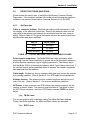
1.4 UNPACKING
Upon receipt, carefully examine the carton and its contents. If there is damage to
the carton that results in damage to the unit, contact the carrier immediately.
Retain the carton and packing materials in the event the carrier wishes to witness
the shipping damage. Failing to report shipping damaging immediately may
forfeit any claim against the carrier. In addition, notify Spectracom Corporation of
shipping damage or shortages, to obtain a replacement or repair services.
Remove the packing list from the envelope on the outside of the carton. Check
the packing list against the contents to be sure all items have been received,
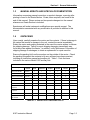
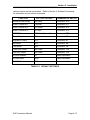
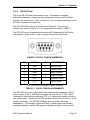
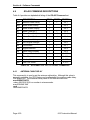
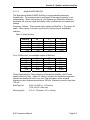
including an instruction manual and ancillary kit. Table 1-1 lists the items
included in the various Model 8197 ancillary kits.
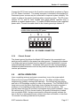
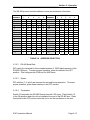
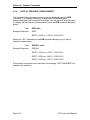
MODEL 8197 ANCILLARY KITS
Description Part
Number
Standard
Power
Option 03
Distribution
Option 52
±12 VDC
Option 53
±24 VDC
Option 53R
+24 VDC
Option 54
±48 VDC
Fuse, 2.0A Slo-Blo F012R0 1 1 0 0 1 0
Fuse, 1.5A Slo-Blo F011R5 1 1 0 0 0 0
Fuse, 10.0A Fast-Blo F0110R 0 0 1 0 0 0
Fuse, 6.25A Slo-Blo F016R0 0 0 0 1 0 0
Fuse, 3.0A Slo-Blo F013R0 0 0 0 0 0 1
Line Cord W01000 1 1 0 0 0 0
Terminal Block,
6-position
P13006 1 1 1 1 1 1
Terminal Block,
7 position
P13007 1 1 1 1 1 1
Terminator, 50-ohm 004492 4 0 4 4 4 4
Terminator,
DC isolated
004490 0 4 0 0 0 0
TABLE 1-1 MODEL 8197 ANCILLARY KITS

Page 1-4 8197 Instruction Manual
1.5 Specifications
This section contains specifications for the standard Model 8197 GPS Ageless
Oscillator, Model 8225 GPS Antenna, Model 8226 Impulse Suppressor and
Model 8227 Inline Amplifier. Specifications pertaining to Model 8197 options and
related accessory items are found in Section 5.
1.5.1 Receiver
Received Standard: L1 C/A Code transmitted at 1575.42 MHz.
Satellites Tracked: Up to 8 simultaneously.
Acquisition Time: Typically <20 minutes during initial installation;
typically <1 minute thereafter.
Acquisition Sensitivity: -105 dBm to -137 dBm.
Tracking Sensitivity: -139 dBm.
Timing Accuracy: <50 nanoseconds with SA on in Position Hold mode.
1.5.2 Standard Frequency Outputs
Signal: 10-MHz sine wave derived from GPS disciplined
Rubidium oscillator.
Connector: BNC female, one front panel, and four rear panel.
Signal Level: 750 mV rms ±2 dB into 50 ohms.
Source Impedance: 50 ohms.
Harmonics: better than 30 dB down.
Spurious: better than 40 dB down.
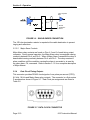
Signature Control: The Frequency Outputs can be configured with
Signature Control. Under Signature Control, the
outputs are removed whenever a Major Alarm is
asserted. The outputs are restored when the fault
condition is corrected. The Signature Control feature
is set via the RS-232 communication port.

_____________________________________ Section 1: General Information
8197 Instruction Manual Page 1-5
Output Options: The following options are available for various Model
8197 applications:
Option 03 Distribution Amplifier: Allows the Model
8197 to drive Spectracom distribution products. This
option adds a 12 Volt DC offset to the rear panel
Frequency Outputs.
Option 06: Changes the Frequency Outputs and the
front panel 10-MHz output to 12.8 MHz.
Option 07: Changes the Frequency Outputs and the
front panel 10 MHz output to 5.0 MHz.
Option 08: Changes the Frequency Outputs and the
front Panel 10 MHz output to 1.0 MHz.
1.5.3 Frequency Standard Stability
Locked Accuracy: 24-Hour Average accuracy is typically ±1 x 10
-12
when
locked to GPS.
Unlocked Accuracy: Corrections are applied to the Rubidium oscillator
based upon learned aging. Holdover accuracy is
typically <2 microseconds/day.
Short Term: 3 x 10
-11
/ 1 second.
1 x 10
-11
/ 10 seconds.
3 x 10
-12
/ 100 seconds.
Recovery: During a power failure, the oscillator control value is
retained and the connected standby supply provides
power to the oscillator and GPS receiver. At power-
on, the disciplined oscillator returns to the set
frequency plus any incurred aging.
Without standby power Rubidium lock < 4 minutes @
25°C, Oscillator Lock < 4 hours. Retrace 5 x 10
-11
.
Aging Rate: 2 x 10
-11
/day under constant ambient conditions.
1.5.4 1 PPS Output
Signal: One pulse-per-second square wave derived from the
GPS receiver.
Connector: BNC female, front panel.

Section 1: General Information _____________________________________
Page 1-6 8197 Instruction Manual
Signal Level: TTL-compatible into loads >100 ohms.
Pulse Width: 200 milliseconds.
Accuracy: Positive edge within ±50 nanoseconds of UTC when
in Position Hold Mode and NO DELAY selected.
Delay Control: The 1PPS output can be delayed 0 - 1 second in 1
nanosecond (0.001 microsecond) steps. The delay
value is entered via the RS-232 or RS-485
communication port.
1.5.5 1544 kHz Timing Outputs
Signal: 1544 kHz, derived from the GPS disciplined 10 MHz
oscillator.
Connector: RJ-11, rear panel.
Signal Level: RS-485.
Duty Cycle: 50% ± 2%.
Accuracy: Typically ±1.0 x 10
-12
when locked to GPS, 24-hour
average.
Additional Outputs: Major alarm relay contacts; C, NO, NC are provided
on this connector.
1.5.6 2048 kHz Timing Outputs
Signal: 2048 kHz, derived from the GPS disciplined 10 MHz
oscillator.
Connector: RJ-11, rear panel.
Signal Level: RS-485.
Duty Cycle 50 ± 2%.
Accuracy: Typically ±1.0 x 10
-12
when locked to GPS, 24-hour
average.
Additional Outputs: Major alarm relay contacts; C, NO, NC are provided
on this connector.

_____________________________________ Section 1: General Information
8197 Instruction Manual Page 1-7
Optional Outputs: Option 06, 12.8-MHz outputs, changes the 2048-kHz
output to 1.6 MHz.
1.5.7 Data Clock Timing Outputs
Signals: 1PPS, 9.6 kHz, 18.0 kHz, derived from the GPS
disciplined 10 MHz oscillator.
Connector: DB9 female, rear panel.
Signal Level: RS-485.
Duty Cycle: 1PPS: 20% ±5%.
9.6 kHz, 18.0 kHz: 50% ±2%.
Accuracy: The Data Clock 1PPS is made leading edge
synchronized to the recovered GPS 1PPS. Using the
1PPS offset command, 1PO, the Data Clock 1PPS
output can be offset from 0 to 1 second in 0.1
microsecond steps. The Data Clock 1PPS shall be
synchronized within ±500 nanoseconds of other
Model 8195A/8197 receivers having the same 1PO
offset. The 9.6 kHz output is leading edge
synchronized to within ±150 nanoseconds of the Data
Clock 1PPS output.
The 18 kHz output is not leading edge synchronized.
Additional Outputs: Major alarm status is provided on this connector.
Under normal operation, the alarm pin is ground and
high impedance when a Major Alarm is asserted.
1.5.8 Data Sync Timing Outputs
Signals: 17 2/3 Hz, 33 1/3 Hz, 18 kHz, and 64 kHz, derived
from the GPS disciplined 10 MHz oscillator.
Connector: DB15 Female, rear panel.
Duty Cycle: 18 kHz, 64 kHz: 50% ± 2%.
17 2/3: 888 microsecond pulse width.
33 1/2: 208 microsecond pulse width.
Accuracy: The 17 2/3 Hz and 33 1/3 Hz Data Sync outputs are
leading edge synchronized to within ±400
nanoseconds of the Data Clock 1PPS output. Using

Section 1: General Information _____________________________________
Page 1-8 8197 Instruction Manual
the 1PPS offset command, 1PO, the Data Clock
1PPS output can be offset from 0 to 1 second in 0.1
microsecond steps. The Data Clock 1PPS shall be
synchronized within ±500 nanoseconds of other
Model 8195A/8197 receivers having the same 1PO
offset.
The 64 kHz and 18 kHz outputs are not leading edge
synchronized.
Additional Outputs: Major alarm relay contacts; NO , NC and common are
provided on this connector.
Optional Outputs: Option 14, CTCSS Outputs, replaces the 33-1/3 Hz
and17-2/3 Hz signals with CTCSS #1 and CTCSS #2
respectively.
Option 06, 12.8 MHz outputs, changes the 64-kHz
output to 50 kHz.
1.5.9 Indicator Lamps
Front panel LEDs when lit, indicate the following:
Power: Primary power source is connected and switched ON.
Tracking GPS: Receiver is locked to at least one GPS satellite.
Oscillator Locked: Oscillator is disciplined to the received GPS signal.
Major Alarm: Alarm condition classified as “major” is active.
Minor Alarm: Alarm condition classified as “minor” is active.
Optional Indicators: Receivers equipped with Option 2, Internal Battery
Backup, include indicator lamps to communicate
battery status: Ready, Charging, and Replace.
1.5.10 Alarms
Alarm relays allow remote monitoring of operational status. Relay contacts are
provided for Major Alarms and Minor Alarms. Alarm status is also included in
performance and status logs obtained using software commands.

_____________________________________ Section 1: General Information
8197 Instruction Manual Page 1-9
1.5.10.1 Alarm Classifications
Major Alarm: A Major alarm is asserted when detected faults compromise output
accuracy. The alarm relays reset when the fault condition is corrected. Faults
and conditions listed below actuate a Major Alarm:
Frequency Error Alarm: Measured oscillator frequency error exceeds
1 x 10
-9
or whenever an AT2 Alarm is asserted. A Frequency Alarm is
also asserted at Power On.
GPS Tracking Timeout 2: The AT2 time period allotted for operation
without tracking a satellite has expired.
GPS Tracking Timeout 3: The AT3 time period allotted for operation
without tracking a satellite has expired.
CPU Fault: The CPU is unable to communicate with the GPS receiver.
Test Mode: Unit has been placed in TEST MODE operation.
Free Run: The automatic frequency control feature has been disabled.
Short Gate: Gate time is shortened for test purposes, measurement
resolution is reduced.
Minor Alarm: A minor alarm is asserted when failures detected do not
immediately affect output accuracy. The alarm relays reset when the fault
condition is corrected. Faults and conditions listed below actuate a Minor Alarm:
Output Fault: No output is detected from one or more of the four rear
panel Frequency Outputs. Fault could be caused by a shorted cable,
reflections due to an unterminated cable or removed by a Major Alarm
when Signature Control is enabled.
Oscillator Adjust: Warns that oscillator is operating within 10% of the
minimum or maximum control setting. The oscillator requires manual
adjustment.
GPS Tracking Timeout 1: The AT1 time period allotted for operation
without tracking a minimum of four qualified satellites has expired. An
AT1 Alarm is also asserted during start-up.
Low Quality Alarm: Warns of low GPS signal quality. The alarm is
asserted whenever the "Q" value in Tracking Histogram is below 3000.
Replace Battery: Internal battery pack, Option 02 only, has failed daily

Section 1: General Information _____________________________________
Page 1-10 8197 Instruction Manual
test, needs replacement.
Test Mode: Unit is placed in Test Mode operation from RS-232
communication port.
Antenna Problem: Warns that the antenna is not connected or a cable
short or open is detected.
1.5.10.2 Tracking Alarm Classifications
Three configurable alarm tracking timeouts, AT1, AT2, and AT3, indicate how
long the Model 8197 has been unable to track any satellites. Countdown timers
are started whenever the receiver is not tracking satellites. As the period
configured for each Alarm Timeout expires, the associated tracking alarm is
asserted. The alarm timeouts are configured via the RS-232 and RS-485
communication ports. Timeout range is 1 second to 999 days. Alarm tracking
status is provided to the communication ports using the STAT and DAL
commands.
AT1 (Alarm Tracking Timeout 1): Period of time the receiver has not tracked at
least four qualified satellites has expired. Factory default is 1 minute. This is a
Minor Alarm that also extinguishes front panel TRACKING GPS lamp. The AT1
Alarm resets upon acquisition of at least four qualified satellites for one minute.
AT2 (Alarm Tracking Timeout 2): Period of time the receiver has not tracked at
least four qualified satellites has expired. Factory default is 2 hours 30 minutes.
This condition is classified as a Major Alarm. An AT2 alarm asserts a frequency
alarm and extinguishes the OSC LOCK lamp. The AT2 Alarm resets when the
receiver has reacquired a minimum of four qualified satellites for one minute.
AT3 (Alarm Tracking Timeout 3): Period of time the receiver has not tracked at
least four qualified satellites has expired. Factory default is 30 days. This is a
Major Alarm. The AT3 Alarm resets when the receiver has reacquired a
minimum of four qualified satellites for one minute.
1.5.10.3 Alarm Interface
Alarm relay contacts are provided on the Alarm Outputs, Data Sync, Data Clock,
1544 kHz and 2048 kHz timing output connectors.
Alarm Outputs: Major Alarm, Minor Alarm.
Connector: 7-position terminal block, rear panel.
Contacts: NO, NC, and Common.
Contact Rating: 30 VDC, 2 Amps.
Data Sync: Major Alarm.

_____________________________________ Section 1: General Information
8197 Instruction Manual Page 1-11
Connector: DB15 Female, rear panel.
Contacts: NO, NC and Common.
Contact Rating: 30 VDC, 500 milliamps.
Data Clock: Major alarm.
Connector: DB9 Female, rear panel.
Contact Rating: 30 VDC, 500 milliamps.
1544 kHz: Major alarm.
Connector: RJ-11, rear panel.
Contacts: NO, NC and Common
Contact Rating: 30 VDC, 250 milliamps.
2048 kHz: Major alarm.
Connector: RJ-11, rear panel.
Contacts: NO, NC and Common
Contact Rating: 30 VDC, 250 milliamps.
1.5.11 Communication Ports
The Model 8197 has a front panel RS-232 and a rear panel RS-485
communication port. The communication ports are used to monitor and set
operational parameters.
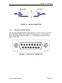
1.5.11.1 RS-232 Com
Signal: RS-232C, DCE.
Connector: DB9 female, front panel.
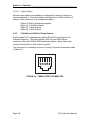
Bit Rate: 9600 Baud.
Character Structure: ASCII, 1 start, 8 data, 1 stop, no parity, xon/xoff flow
control.
1.5.11.2 RS-485 Com
Signal: RS-485, 1 pair Transmit, 1 pair Receive.
Connector: RJ-11, rear panel.
Impedance: Hi Z /120 ohms, switch selectable.
Bit Rate: 9600 baud.
Address: 0 - 31, switch selectable.
Character Structure: ASCII, 1 start, 8 data, 1 stop, no parity.
Page is loading ...
Page is loading ...
Page is loading ...
Page is loading ...
Page is loading ...
Page is loading ...
Page is loading ...
Page is loading ...
Page is loading ...
Page is loading ...
Page is loading ...
Page is loading ...
Page is loading ...
Page is loading ...
Page is loading ...
Page is loading ...
Page is loading ...
Page is loading ...
Page is loading ...
Page is loading ...
Page is loading ...
Page is loading ...
Page is loading ...
Page is loading ...
Page is loading ...
Page is loading ...
Page is loading ...
Page is loading ...
Page is loading ...
Page is loading ...
Page is loading ...
Page is loading ...
Page is loading ...
Page is loading ...
Page is loading ...
Page is loading ...
Page is loading ...
Page is loading ...
Page is loading ...
Page is loading ...
Page is loading ...
Page is loading ...
Page is loading ...
Page is loading ...
Page is loading ...
Page is loading ...
Page is loading ...
Page is loading ...
Page is loading ...
Page is loading ...
Page is loading ...
Page is loading ...
Page is loading ...
Page is loading ...
Page is loading ...
Page is loading ...
Page is loading ...
Page is loading ...
Page is loading ...
Page is loading ...
Page is loading ...
Page is loading ...
Page is loading ...
Page is loading ...
Page is loading ...
Page is loading ...
Page is loading ...
Page is loading ...
Page is loading ...
Page is loading ...
Page is loading ...
Page is loading ...
Page is loading ...
Page is loading ...
Page is loading ...
Page is loading ...
Page is loading ...
Page is loading ...
Page is loading ...
Page is loading ...
Page is loading ...
Page is loading ...
Page is loading ...
Page is loading ...
Page is loading ...
Page is loading ...
Page is loading ...
Page is loading ...
Page is loading ...
Page is loading ...
Page is loading ...
Page is loading ...
Page is loading ...
-
 1
1
-
 2
2
-
 3
3
-
 4
4
-
 5
5
-
 6
6
-
 7
7
-
 8
8
-
 9
9
-
 10
10
-
 11
11
-
 12
12
-
 13
13
-
 14
14
-
 15
15
-
 16
16
-
 17
17
-
 18
18
-
 19
19
-
 20
20
-
 21
21
-
 22
22
-
 23
23
-
 24
24
-
 25
25
-
 26
26
-
 27
27
-
 28
28
-
 29
29
-
 30
30
-
 31
31
-
 32
32
-
 33
33
-
 34
34
-
 35
35
-
 36
36
-
 37
37
-
 38
38
-
 39
39
-
 40
40
-
 41
41
-
 42
42
-
 43
43
-
 44
44
-
 45
45
-
 46
46
-
 47
47
-
 48
48
-
 49
49
-
 50
50
-
 51
51
-
 52
52
-
 53
53
-
 54
54
-
 55
55
-
 56
56
-
 57
57
-
 58
58
-
 59
59
-
 60
60
-
 61
61
-
 62
62
-
 63
63
-
 64
64
-
 65
65
-
 66
66
-
 67
67
-
 68
68
-
 69
69
-
 70
70
-
 71
71
-
 72
72
-
 73
73
-
 74
74
-
 75
75
-
 76
76
-
 77
77
-
 78
78
-
 79
79
-
 80
80
-
 81
81
-
 82
82
-
 83
83
-
 84
84
-
 85
85
-
 86
86
-
 87
87
-
 88
88
-
 89
89
-
 90
90
-
 91
91
-
 92
92
-
 93
93
-
 94
94
-
 95
95
-
 96
96
-
 97
97
-
 98
98
-
 99
99
-
 100
100
-
 101
101
-
 102
102
-
 103
103
-
 104
104
-
 105
105
-
 106
106
-
 107
107
-
 108
108
-
 109
109
-
 110
110
-
 111
111
-
 112
112
-
 113
113


Spectracom 8197 GPS Ageless Master Oscillator User manual
- Category
- Smoke detectors
- Type
- User manual
- This manual is also suitable for
Ask a question and I''ll find the answer in the document
Finding information in a document is now easier with AI
Related papers


Other documents
-
 Orolia GPS Ageless Master Oscillator 8194B, 8195B, 8197B User manual
-
 Orolia 8195A GPS Ageless Oscillator User manual
-
 Orolia 8140MT User manual
-
 Orolia TTS 200 GPS Time Server User manual
-
 Orolia 8194 GPS Ageless Oscillator User manual
-
Legrand Satellite Surge Protector, IS-0285 Installation guide
-
 Orolia 8130 User manual
-
 Orolia TTS 220 Network Time Server User manual
-
-
 Orolia NetClock/GPS 9283 User manual


