Page is loading ...

PARTS, SERVICE
& REPAIR BULLETIN
Issue Date: March 2011Revision: D Form No.: 0056-1966
ESS3
ESS4
ESS7
EST4
ESL4
ELC4
Pressure Regulators

INDEX
Section Models
Page
1
2
3
4
5
ESS3 & ESS4
ESS7, EST4, ESL4 & ELC4
Future EDGE Models
Future EDGE Models
Future EDGE Models
- i -
01
15
--
--
--

ESS3/ESS4
- 1 -
SECTION 1
SECTION 1
SERVICE & REPAIR INSTRUCTIONS
ESS3 & ESS4 Single Stage EDGE™ Series Regulators
WARNING!
Apparatus improperly operated, maintained or repaired can be dangerous!
Service and repair of VICTOR apparatus should only be performed by a Qualified Repair
Technician. The term “Qualified Repair Technician” refers to repair personnel capable
of servicing apparatus in strict accordance with all applicable Victor “Parts & Service
Bulletins” and literature. Improper service or repair, or modification of the product,
could result in damage to the product or injury to the operator.
Protect your investment! Some parts and accessories manufactured by others may fit
VICTOR apparatus, but not conform to VICTOR’s exacting standards for quality, fit and
function. For your own protection and the protection of your investment, specify and
use only
VICTOR genuine parts and accessories. It’s the only way to guarantee the
level of performance, safety and reliability that you expect from
VICTOR.
GLOSSARY – COMMONLY USED TERMS
OUTLET PRESSURE: The pressure measured at the Regulator’s outlet port.
INLET PRESSURE: The pressure measured immediately at the Regulator’s entry.
DROP: A change in outlet pressure from a no-flow to flowing condition while the inlet
pressure remains constant.
RISE: An increase in outlet pressure as the inlet pressure decreases.
CREEP: A gradual increase in outlet pressure.
RECOMMENDED TOOLS & SUPPLIES FOR REPAIR PROCEDURES
• Inlet Swivel Assembly Plug
•
1
/2”,
5
/8”,
9
/16”,
11
/16” and
3
/4” Sockets
• Socket Wrench
• Torque Wrench
•
7
/16”,
3
/4” and
13
/16” Open End Wrenches
•
1
/8”,
9
/64”,
3
/16” and
1
/4” Hex Keys
• Bench Vise
• Repair Tool RT-180 (8” Leverage Bar with
1
/4-18 NPT [M] End)
• Oxygen-compatible Teflon® Tape
• Loctite® #222 Threadlocker
• CHRISTO-LUBE® #129 Lubricant.

KNOB DECAL
6
SCREW
7
WASHER
8
KNOB
9
BONNET SCREWS
10
(a)
BONNET
2
O-RING
17
NOZZLE
16
DIAPHRAGM ASSM.
4
ADJUSTING SPRING
15
SCREW
7
WASHER
14
GUIDE BUSHING
13
DRIVE SCREW
12
THRUST WASHER
11
FRICTION DAMPER
21
GLAND
20
VALVE SPRING
19
SEAT ASSM.
18
BODY
1
INELT NUT
23
FILTER
24A
INLET SWIVEL
24
PIPE PLUG
25
OUTLET
26
RELIEF VALVE
27
(b)
L.P. GAUGE
28
H.P. GAUGE
29
GAUGE GUARD
3
SCREW
5
SCREW
5
BONNET DECAL (GAS)
30
REAR BODY DECAL (GAS I.D.)
31
SEAT GUIDE
22
(See Detail A)
BACK-UP RING
4A
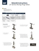
(c)
Diaphragm
Assembly
Body
Bonnet
Back-Up Ring
Orientation
In Assembly
(c)
EXPLODED VIEW - ESS3 AND ESS4 MODELS
LOCK WASHER
8A
BODY
27A
SEAT RET.
27C
DISC
27E
SEAT
27B
UPPER SEAT
27D
SPRING
27F
CAP
27G
DETAIL A - Relief Valve
(b)
(a)
ESS3 models use five Screws for Bonnet, ESS4 models use six Screws.
(b) Pipe Plug replaces Relief Valve on fuel gas models (510, 300, 993).
(c) Used on ESS4 “E” Range (200 PSIG Delivery) models only.
SPRING BUTTON
27I
VENTED CAP
27H
ADJ. SCREW
27J
CAP NUT
27K
Vented
Non-Vented
- 2 -
ESS3/ESS4 SECTION 1

ESS3 ESS4
Description Part No. Part No. Qty.
1
Body 0701-0705 0701-0706 1
2
Bonnet 0720-0343 0720-0342 1
3
Gauge Guard 1429-0071 1429-0070 1
4
Diaphragm Assembly 0730-0024 TABLE 1 1
4A
Back-Up Ring --- TABLE 1 1
5
Screw (Gauge Guard) 1400-0248 1400-0239 2
6
Decal, Knob 1415-0788 1415-0791 1
7
Screw 2
8
Washer 1
9
Knob 1
10
Socket Head Cap Screw (b)
11
Thrust Washer 1
12
Drive Screw 1
13
Guide Bushing Assm. 1
14
Washer, Special 1
15
Adjusting Spring 1
16
Nozzle 1
17
O-Ring (Nozzle Body) 1
18
Seat Assembly 1
19
Valve Spring 1
20
Gland 1
21
Friction Damper 1
22
Bottom Guide 1
23
Inlet Nut 1
24
Inlet Swivel w/Filter 1
24A
Inlet Filter 1
25
Pipe Plug 1
26
Outlet Connection 1
27
Relief Valve 1
28
Gauge, Low Pressure 1
29
Gauge, High Pressure 1
30
Decal, Bonnet Gas I.D. 1
31
Decal, Rear Body Gas Info. 1
(a) Cylinder models only.
(b) ESS3 uses five (5) screws, ESS4 uses six (6) screws.
TABLE 2
TABLE 2
TABLE 2
TABLE 3
TABLE 1
TABLE 1
TABLE 2
TABLE 2
0717-0003 (a)
1105-0014
0708-0018
1408-0033
0708-0003
0762-0006
TABLE 1
TABLE 2
1407-0282
TABLE 2
1406-0220
1406-0006
0750-0201
0750-0203
1400-0239
1406-0050
TABLE 2
1400-0246
Ref.
No.
Items most commonly required for regulator repair and recommended for stock.
PARTS LIST - ESS3 and ESS4 Model Regulators
8A
Lock Washer 1
1406-0215
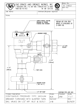
ESS3 Model
(ESS3-125-540 Shown)
ESS4 Model
(ESS4-125-540 Shown)
5.69
2.18
5.88
2.55
3.23
3.82
INLET
OUTLET
RELIEF
INLET
OUTLET
RELIEF
- 3 -
ESS3/ESS4 SECTION 1

TABLE 3 - Relief Valve
Description 40 psi Delivery 125 psi Delivery 200 psi Delivery 15 psi Delivery 40 psi Delivery 125 psi Delivery 200 psi Delivery
60 200 400 30 60 200 400
27
Relief Valve Complete Assembly
or Pipe Plug
27A
Body
0601-0006 0601-0006 0601-0006 0601-0004 0601-0004 0601-0004 0601-0006
27B
Seat 0608-0006 0608-0006 0608-0009 0608-0006 0608-0006 0608-0006 0608-0009
27C
Seat Retainer 0609-0006 0609-0006 0609-0006 0609-0003 0609-0003 0609-0003 0609-0006
27D
Upper Seat 0608-0023 0608-0023 0608-0021 0608-0018 0608-0018 0608-0018 0608-0023
27E
Disc 1406-0017 1406-0017 1406-0017 1406-0016 1406-0016 1406-0016 1406-0017
27F
Spring 0610-0016 0610-0016 0610-0014 0610-0004 0610-0005 0610-0008 0610-0013
27G
Cap --- --- --- 0614-0004 0614-0004 0614-0004 0614-0006
27H
Cap (Vented) 0614-0016 0614-0016 0614-0016 --- --- --- ---
27I
Spring Button
0606-0005 0606-0005 0606-0005 --- --- --- ---
27J
Adjusting Screw 1401-0007 1401-0008 1401-0008
--- --- --- ---
27K
Cap Nut 1403-0024 1403-0024 1403-0024
--- --- --- ---
0600-0005 0600-0014 0600-0018
Acetylene
All Models
---
---
---
---
---
---
---
---
---
---
---
---
Pipe Plug
1105-0014
0600-0060 0600-0066 0600-0071 0600-0003
All Other ModelsHydrogen (Vented Relief Valve)
Relief Valve Nominal Set Pressure
Ref.
No.
LP Gas
All Models
---
---
---
---
---
---
---
---
---
---
---
---
Pipe Plug
1105-0014
TABLE 2 - Inlet & Outlet, Seat Assembly & Nozzle, Color Coded Items
Gas Inlet Type I.D. Color ESS3 ESS4 ESS3 ESS4 ESS3 ESS4
Oxygen CGA 540 GREEN 0790-0209 0790-0200 0702-0085 0702-0068 0740-0158 0740-0131 0967-0044 0967-0032 0950-0068 1415-0790 1415-0792
Oxygen 992 GREEN 0790-0209 0790-0200 0702-0085 0702-0068 0740-0158
0740-0131
0992-0003 0970-0015 0950-0068 1415-0790 1415-0792
Argon/Helium/Nitrogen CGA 580
BLACK
0790-0214 0790-0208 0702-0085 0702-0068 0740-0158
0740-0131
0973-0003 0970-0015 0950-0017 (e) 1415-0799 1415-0798
Air (Industrial) CGA 590
BLACK
0790-0214 0790-0208 0702-0085 0702-0068 0740-0158
0740-0131
0974-0003 0970-0015 0960-0014 1415-0805 1415-0804
Air (Breathing) CGA 346
YELLOW
0790-0219 0790-0216 0702-0085 0702-0068 0740-0158
0740-0131
0972-0015 0972-0009 0960-0014 1415-0807 1415-0806
Carbon Dioxide CGA 320 (d)
GREY
0790-0212 0790-0206 0702-0085 0702-0068 0740-0158
0740-0131
0985-0030 0985-0058 (d) 0950-0017 (e) 1415-0801 1415-0800
Nitrous Oxide CGA 326 BLUE 0790-0211 0790-0205 0702-0085 0702-0068 0740-0158
0740-0131
0963-0015 0963-0009 0950-0080 1415-0803 1415-0802
Hydrogen & Methane CGA 350 RED 0790-0210 0790-0204 0702-0085 0702-0068 0740-0158
0740-0131
0983-0003 0983-0005 0960-0029 1415-0809 1415-0808
Acetylene CGA 510 RED 0790-0210 0790-0204 0970-0003 0970-0015 0960-0029 1415-0789 1415-0793
Acetylene CGA 300 RED 0790-0210 0790-0204 0968-0003 0968-0005 0960-0029 1415-0789 1415-0793
Acetylene 993 RED 0790-0210 0790-0204 0993-0003 0970-0015 0960-0029 1415-0789 1415-0793
LP Gases CGA 510 ORANGE 0790-0213 0790-0207 0970-0003 0970-0015 0960-0029 1415-0797 1415-0796
(f) To replace Lens only - Replacement Lens Part No. 1429-0029.
(d) CGA 320 inlet requires inlet washer part number 1408-0065.
(e) Flow Gauge (FG) models must use Outlet Connection with orifice - Part No. 0950-0120.
0740-0101
16
Nozzle
Inlet Nut
Inlet Swivel
(w/Filter)
0740-0101
0740-0101
0740-0101
Outlet
Connection
Decal, Rear
Body Gas Info.
9
Adjusting Knob (w/Decal)
Decal, Bonnet
Gas I.D.
18
Seat Assembly
0702-0068
0702-0068
0702-0068
0702-0068
23
24
26 30 31
Ref. No.
TABLE 1 - Diaphragm, Adjusting Spring & Gauges
ESS3-FG-580
Description ESS3-FG-320 ESS3-40- ESS4-40- ESS3-125- ESS4-125- ESS3-200- ESS4-200-
4
Diaphragm Assembly 0730-0024 0730-0063 0730-0024 0730-0063 0730-0063 0730-0024 0730-0024 0730-0063 0730-0024 0730-0063 0730-0024 0730-0068
4A
Back-Up Ring
--- --- --- 0736-0002
15
Adjusting Spring 0761-0107 0761-0089 0761-0060 0761-0093 0761-0098 0761-0060 0761-0060 0761-0093 0761-0080 0761-0098
28
Gauge, Low Pressure (f) 1424=0512 1424=0516
29
Gauge, High Pressure (f) 1424=0513 1424=0511
All Other ModelsFlow Gauge Models
1424=0513
1424=0511
0761-0098
1424=0515
1424=0511
--- ---
1424=0512
1424=0511
LP Gas
ESS3-40-510LP ESS4-40-510LP ESS4-125-510LP
LP Gas
---
1424=0515
1424=0513
ESS3-15-510 ESS4-15-510
Ref.
No.
Acetylene
1424=0514
1424=0513
--- --- --- --- ---
- 4 -
ESS3/ESS4 SECTION 1

ESS3/ESS4
- 5 -
SECTION 1
SERVICE & REPAIR PROCEDURES
ESS3 & ESS4 Single Stage EDGE™ Series Regulators
DISASSEMBLY PROCEDURES
Refer to the exploded view for reference numbers [Shown in brackets]
1. Mount the Inlet Swivel Assembly Plug in the Bench Vise and firmly attach the Regulator.
2. Remove the Knob Decal [6], and remove the #10-32 Screw [7], Lock Washer [8A] and
Washer [8] located inside the Knob [9]. The Knob can now be removed.
3. Remove the 5 (for ESS3) or 6 (for ESS4) Socket Head Cap Screws [10]. The Bonnet [2]
can now be removed.
TIP: Be careful when removing the Bonnet, as the Diaphragm Assembly can
sometimes stick to it when disassembling.
4. Remove the Drive Screw [12], Guide Bushing [13], and Thrust Washer [11]. The Guide
Bushing can be separated from the Drive Screw by removing the #10-32 Screw [7] and
Washer [14] installed in the bottom of the Drive Screw.
TIP: Make sure you’ve got the Thrust Washer. If it’s not sitting on top of the Drive
Screw, it may still be up inside the Bonnet.
5. Remove the Adjusting Spring [15], Diaphragm Assembly [4], and Back-Up Ring [4A] (if
so equipped), and then remove the Nozzle [16] from the Body.
6. Remove the Seat Assembly [18], Valve Spring [19], Gland [20], Friction Damper [21]
and Bottom Guide [22] from the Body.
7. Remove the Relief Valve or Pipe Plug [27], Outlet Connection [26] and Pipe Plug [25] (if
necessary) from the Body.
8. Screw the Leverage Bar Tool RT-180 into the outlet port of the Body (lightly hand tight),
and use the bar to unscrew the Body off the Inlet Swivel [24].
TIP: Watch the Inlet Swivel while trying to turn the Body. If the Swivel is turning with
the Body, then you need to tighten the Inlet Nut tighter on the Inlet Swivel Assembly
Plug.
9. Holding the Body by hand, or lightly in the Bench Vise (with the top surface of the body
protected from damage), remove the Gauge Guard [3] (held on by two screws [5]) and
then remove the Gauges [28, 29].
TIP: Step 9 can be done before Step 8 if desired, but it’s usually easier to remove the
Gauge Guard and Gauges with the Inlet Swivel Assembly Plug out of the way.
NOTE ON ESS4 MODELS: The lower Gauge Guard Screw cannot be accessed until
the Relief Valve has been removed (if so equipped). Subsequently, the Gauge Guard
(and Gauges) must be installed into the Body prior to installing the Relief Valve.
10. If necessary, disassemble the Relief Valve as shown in DETAIL A.
CAUTION! Discard the used Nozzle O-Ring, Inlet Filter, Diaphragm Assembly,
Seat Assembly and Friction Damper. Replace them with new parts each time you
assemble a Regulator.

ESS3/ESS4
- 6 -
SECTION 1
All of these recommended components are available together in convenient repair kits for
your ESS3 or ESS4 model Regulator:
Repair Kit Part No. Description
RK-ESS3-HP 0790-0162 ESS3 Repair Kit for Oxygen, Inert Gases, Air, CO
2
,
N
2
O, Hydrogen.
RK-ESS4-HP 0790-0163 ESS4 Repair Kit for Oxygen, Inert Gases, Air, CO
2
,
N
2
O, Hydrogen.
RK-ESS4-HP200 0790-0164 ESS4 Repair Kit - 200 PSIG Delivery Models Only -
for Oxygen, Inert Gases, Air, CO
2
, N
2
O, Hydrogen.
RK-ESS3-F 0790-0165 ESS3 Repair Kit for Acetylene, LP Gas.
RK-ESS4-F 0790-0166 ESS4 Repair Kit for Acetylene, LP Gas.
CLEANING PARTS
It is recommended to clean all metal parts for oxygen service, regardless of Regulator Model
being repaired. There are several ways to clean components for oxygen service; the
following standards are recommended reading for more detailed information on methods and
processes:
• CGA G-4.1 “Cleaning Equipment for Oxygen Service”
• ASTM G-93 “Standard Practice for Cleaning Methods and Cleanliness Levels for
Material and Equipment Used in Oxygen-Enriched Environments”
• ASTM G-127 “Standard Guide for the Selection of Cleaning Agents for Oxygen
Systems”
For metal parts, Victor brand suggests using CCI Envirospray Liquid, used per the
manufacturer's instructions, followed by a hot water rinse and thorough drying. Additional
information can be found at
http://www.ccichemical.com.
DO NOT allow non-metal parts to come in contact with cleaning solvents. Cleaning solvents
can cause non-metal parts to swell and/or crack. To clean these parts, use a non-petroleum
based mild soap solution, followed by a thorough rinsing in water. Dry parts completely prior
to reassembling.
ASSEMBLY PROCEDURES
Refer to the exploded view for reference numbers [Shown in brackets]
IMPORTANT NOTES ABOUT SEALING PIPE THREADS:
• When using Teflon® tape where noted: Apply two to three layers around the
threads, leaving the first thread clean. Insure your Teflon® tape is oxygen-
compatible.
• When using Loctite® #222 Threadlocker where noted: Apply two to three drops
to the second and third thread, leaving the first thread clean.

ESS3/ESS4
- 7 -
SECTION 1
1. Wrap the Low and High Pressure Gauges [28, 29] with Teflon® tape.
2. Holding the Body [1] by hand, or lightly in the Bench Vise (with the top surface of the
Body protected from damage), install the Gauges into the Body and torque each to 10 ft-
lbs minimum. Then install the Gauge Guard [3] using the two mounting Screws [5],
tightening them until snug (the Gauge Guard firmly held in position).
TIP: If you cannot get a torque wrench on the Gauges, some simple rules will help
insure adequate tightness: When the Gauges are tight, nearly all of the
1
/8-27 NPT
Gauge threads will disappear into the Body. You should only see one to two turns of
complete thread remaining. Additionally, when the Gauge Guard is in position, the
face of each Gauge should be at least
1
/32” away from the underside of the Gauge
Guard. If the Gauges are closer to the Gauge Guard than that, tighten the Gauges
tighter as needed (one full revolution of the
1
/8-27 NPT Gauge thread will move the
Gauge closer to the Body by approximately
1
/32”). Be sure to note the orientation of
the Gauge face – always go tighter to line up Gauge dial artwork.
3. Install the new Filter [24A] into the Inlet Swivel [24], and apply either Teflon® tape or
Loctite® #222 to the Inlet Swivel threads.
4. If not already in place, mount the Inlet Swivel Assembly Plug back in the Bench Vise.
Firmly attach the Inlet Swivel and Inlet Nut [23] onto the Inlet Swivel Assembly Plug.
5. Screw the Body onto the Inlet Swivel, screw the Leverage Bar Tool RT-180 into the outlet
port of the Body (light hand tight), and then use the Leverage Bar to tighten the Body
onto the Inlet Connection. At this point, tighten enough so that the body cannot be turned
by hand without the assistance of the Leverage Bar. Final torque for the Inlet Connection
will occur in upcoming STEP 10.
6. Apply either Teflon® tape or Loctite® #222 to the Pipe Plug [25] threads. Install the Pipe
Plug into the rear Body high pressure port, and torque to 15 ft-lbs.
7. Preassemble the Relief Valve (if so equipped): Assemble (or reassemble) the Relief
Valve [27] as shown in DETAIL A. Use no lubricants or sealants. If your Regulator
model has a Pipe Plug instead of a Relief Valve, or if your Relief Valve is already
assembled and tested, you can skip to STEP 10.
8. To ensure proper Relief Valve performance, perform the following test procedures before
assembling the Relief Valve in the Regulator.
a. Attach the Relief Valve to a 450 PSIG source of oil-free air or dry nitrogen.
b. Slowly pressurize the Relief Valve, increasing to the recommended blow-off pressure
listed below. Note that
VICTOR Relief Valves are stamped with their nominal set
pressure, in case you’re unsure which Relief Valve you have.
Non-Vented Relief Valves:
If the Relief Valve vents before the minimum blow-off pressure is reached, then a
second Disc [27E] may be added.
If it still vents, then the Spring [27F] must be replaced.
Vented Relief Valves:
If the Vented Relief Valve fails to vent within the recommended blow-off pressure,
reset the Adjusting Screw [27J] as necessary and perform this step again. Make
sure you fully bleed off all pressure each time you test for blow-off pressure.

ESS3/ESS4
- 8 -
SECTION 1
Regulator Max.
Delivery Pressure
Mating Relief
Valve (Nominal)
Recommended
Blow-off Pressure
15 PSIG 30 PSIG 27 to 33 PSIG
40 PSIG 60 PSIG 55 to 66 PSIG
125 PSIG 200 PSIG 180 to 220 PSIG
200 PSIG 400 PSIG 360 to 440 PSIG
9. When all testing is completed, bleed pressure off the Relief Valve. Install the Cap Nut
[27K] on the Vented Relief Valve.
10. Apply either Teflon® tape or Loctite® #222 to the Relief Valve (or Pipe Plug) [27]
threads. Install the Relief Valve (or Pipe Plug) into the Body and torque to 15 ft-lbs.
11. Apply only Loctite® #222 threadlocker to the Outlet Connection [26] threads. Install the
Outlet Connection into the Body and torque to 15 ft-lbs.
12. At this point, thoroughly blow out the Body assembly with pressurized oil-free air or dry
nitrogen to insure it is completely free of chips and debris.
13. Install the Bottom Guide [22] into the Body – it should slip in freely. Note its orientation
when installing – the cupped end with the hex on it should face up.
14. Preassemble the seat components: Push the Friction Damper [21] into the Gland [20],
and then slip the Valve Spring [19], Gland and Friction Damper onto the shaft of the Seat
Assembly [18].
TIP: The Friction Damper should have enough tension to hold the Gland and the
Valve Spring in position on the shaft of the Seat Assembly. If there appears to be no
tension (if the parts just seem to want to fall off), then there may be a problem with
your Friction Damper, or the Friction Damper may not be firmly pushed up in place
inside the Gland.
Then install the preassembled seat components into the Regulator Body – with the
Friction Damper and Gland fitting down into the cup shape of the Bottom Guide.
15. Install the new O-Ring [17] onto the Nozzle [16], taking care to guide it carefully over the
Nozzle threads to avoid nicks or tears. DO NOT use lubricant on the O-Ring. Install the
Nozzle/O-Ring into the Regulator Body and torque to 15 ft-lbs. Note that 15 ft-lbs is the
same recommended torque for the Inlet Connection Swivel, so as you torque down the
Nozzle, you’re also finish-tightening the Inlet Swivel to the correct torque value.
TIP: Watch the Inlet Swivel while you torque down the Nozzle. If the Swivel is turning
with the Body, then you need to tighten the Inlet Nut tighter on the Inlet Swivel
Assembly Plug. You want to be sure that the 15 ft-lbs torque is being applied to both
the Nozzle threads and the Inlet Swivel threads.
16. Preassemble the Adjusting Mechanism: Apply CHRISTO-LUBE® #129 Lubricant to
the entire length of the threads of the Drive Screw [12], and screw the Guide Bushing
[13] onto the Drive Screw (by hand) all the way up until it stops (do not over tighten!).
Note that this is a left hand thread. Next, apply only Loctite® #222 to the threads of the
#10-32 Screw [7], and install the Screw and Washer [14] into the Drive Screw –
tightening until snug.
TIP: Make sure you’ve got the Drive Screw oriented correctly – the Screw and
Washer you just installed should be in the end that’s opposite the square flats.
17. Install the Diaphragm Assembly [4], Adjusting Spring [15], preassembled Adjusting
Mechanism and Thrust Washer [11] onto the Regulator Body. Note that the Diaphragm

ESS3/ESS4
- 9 -
SECTION 1
centers itself in a recessed pocket in the top of the Body. Don’t forget the Thrust
Washer! Regulator function will be impaired without it.
18. Install the Bonnet [2] onto the Body. Take care while slipping the Bonnet down over the
internal components – the ribs inside the Bonnet must slide into the scallops of the Guide
Bushing.
TIP: If your Bonnet still has the Gas I.D. decal on it, make sure you get the Bonnet
oriented correctly with the Gas I.D. decal facing front.
19. Install the five (for ESS3) or six (for ESS4) Socket Head Cap Screws [10] into the
Bonnet. Tighten all bolts until snug, then torque each to 12-15 ft-lbs in the sequence
shown in FIGURE 1.
FIGURE 1 - Torque Sequence for Bonnet Screws
20. Apply a small amount of CHRISTO-LUBE® #129 to the top surface of the Bonnet (the
surface around the square of the Drive Screw), then slip the Knob [9] into position – with
the square hole inside the knob mating to the square shaft of the Drive Screw.
21. Install the #10-32 Screw [7], Lock Washer [8A] and Washer [8] to hold the Knob on.
Torque this Screw a minimum of 30 in-lbs.
22. Apply new Knob or Gas I.D. decals [6, 30, 31] as needed to insure the Regulator
maintains clear visual identification.
TIP: If you’re replacing the rear Body Gas I.D. decal, make sure you don’t cover up
the model number stamped on the Body. The Gas I.D. decal should be positioned
right next to the stamping, with the arrow on the decal pointing to the stamped model
number.
23. Disconnect the Regulator from the Inlet Swivel Assembly Plug. The Regulator is now
ready to test.
RECOMMENDED TOOLS AND SUPPLIES FOR TEST PROCEDURES
• Test Gun (quick opening on/off valve) with #52 (.0635”) restricting orifice
• Source of oil-free air or dry nitrogen

ESS3/ESS4
- 10 -
SECTION 1
TEST PROCEDURES
WARNING!
For your safety, and the safety of others:
• Always test with oil-free air or dry nitrogen only.
• Always wear eye protection while testing a Regulator.
• Always perform all of the following test procedures after reassembling a Regulator.
1. Adjust the Test Manifold to the proper pressure shown in TABLE 4.
Gas Service Manifold Pressure for Testing
Acetylene & LP Gas 250±20 PSIG
CO
2
& N
2
O 100±100 PSIG
Air, Argon, Hydrogen, Helium, Nitrogen,
Oxygen
2000±100 PSIG
TABLE 4 – Edge™ Regulator Test Pressures
2. Attach the Regulator to the Manifold connection or test adapter. Start the nut by hand
(do not force), and tighten securely with a wrench to create a seal.
3. Turn the Regulator Adjusting Knob clockwise two or three times until you feel slight
tension being applied to the Adjusting Spring.
4. Slowly open and close the Manifold Valve two or three times to remove contamination
that may cause malfunctions. Leave the Manifold Valve closed.
a. If no flow comes through the Regulator, determine the cause – refer to the
TROUBLESHOOTING CHART at the end of this section.
5. Turn the Adjusting Knob counterclockwise until it stops, and attach the Test Gun (with a
#52 restricting orifice) to the outlet of the Regulator.
6. Open the Test Manifold Valve and close the Test Gun.
a. Manifold working pressure will appear on the High Pressure Gauge.
b. If the Low Pressure Gauge begins to show pressure building, turn the Test Manifold
off and refer to the TROUBLESHOOTING CHART.
7. Use the values in the following TABLE 5 for all subsequent tests:
Edge™ Model
A
Pressure Set
for Leak Test
B
Pressure Set for
Creep/Drop Test
C
Drop
Allowance
D
Initial Shut-off
Allowance
ESS3-15-
ESS4-15-
15 PSIG 5 PSIG 3 PSIG 1 PSIG
ESS3-40-
ESS4-40-
40 PSIG 10 PSIG 3 PSIG 1 PSIG
ESS3-125-
ESS4-125-
125 PSIG 20 PSIG 4 PSIG 1 PSIG
ESS3-200-
ESS4-200-
200 PSIG 50 PSIG 5 PSIG 1 PSIG
TABLE 5 – Edge™ Regulator Test Values

ESS3/ESS4
- 11 -
SECTION 1
8. LEAK TEST
a. With the Test Gun closed and the Manifold Valve open, adjust the Regulator to
deliver A PSIG.
b. Close the Manifold Valve and turn the Adjusting Knob one turn counterclockwise.
c. Observe the Low Pressure and High Pressure Gauges for five (5) minutes:
1. If the High Pressure Gauge reading drops, there is a leak in the Cylinder Valve,
Inlet Connection, High Pressure Gauge or the rear plugged high pressure port.
2. If the Low Pressure Gauge reading drops, there is a leak in the downstream
equipment, Low Pressure Gauge, Outlet Connection or Relief Valve port.
3. If the High Pressure Gauge reading drops at the same time the Low Pressure
Gauge reading increases, there is a leak in the Regulator Seat.
d. If any leaks are found, isolate if possible using a liquid leak detector, disassemble and
repair or replace parts as needed, and start the test over again. Refer to
TROUBLESHOOTING CHART for more detailed cause and possible corrective
action information.
9. DROP TEST
a. With the Test Gun closed and the Manifold Valve open, adjust the Regulator to
deliver B PSIG.
b. Open the Test Gun and note the new indicated delivery pressure. Drop (indicated
pressure static minus indicated pressure flowing) must not exceed C PSIG.
10. CREEP TEST / SLOW SHUT-OFF TEST
a. With the Test Gun closed and the Manifold Valve open, adjust the Regulator to
deliver B PSIG.
b. Open and close the Test Gun several times to stabilize the Regulator. Leave the test
gun closed.
c. Observe the Low Pressure Gauge for five (5) minutes:
1. During the first minute, an initial shut-off increase of D PSIG is permissible.
2. During the next 4 minutes, no further increase (creep) is allowed.
11. Close the Manifold Valve and release all pressure from the Regulator by opening the
Test Gun. Turn the Adjusting Knob counterclockwise until it stops.
12. Remove the Test Gun from the Regulator.
13. Remove the Regulator from the Test Manifold. The Regulator is now ready to use.

ESS3/ESS4
- 12 -
SECTION 1
TROUBLESHOOTING
CAUSES POSSIBLE CORRECTIVE ACTIONS
1. No gas flows through the Regulator and the High Pressure Gauge does not
indicate pressure.
a. Inlet or Inlet Filter is plugged. Blow 40-45 PSIG of air through the Filter in
reverse direction of the normal gas flow.
b. Empty Supply Cylinder. Replace the Cylinder.
2. No gas flows through the Regulator and the High Pressure Gauge does indicate
pressure.
a. Damaged Adjusting Mechanism or
missing components.
Check the Drive Screw, Guide Bushing and
Thrust Washer – insure they are installed
correctly and moving freely in the Bonnet.
b. Adjusting Knob not installed
correctly.
Make sure the square of the Drive Screw is
properly mated into the square in the
Adjusting Knob.
c. Outlet Connection plugged. Inspect and clear the Outlet Connection of
any debris.
d. Broken Adjusting Spring. Replace the Adjusting Spring.
e. Broken Seat Stem. Replace the Seat Assembly.
3. Gauges do not indicate pressure but gas flows through the Regulator.
a. Defective Gauge(s). Replace Gauge(s).
4. Regulator does not deliver in its designed delivery pressure range.
a. Incorrect Adjusting Spring used
during repair.
Replace with correct Adjusting Spring.
b. Damaged Adjusting Mechanism or
missing components.
Check the Drive Screw, Guide Bushing and
Thrust Washer – insure they are installed
correctly and moving freely in the Bonnet.
5. Regulator hums or clatters while flowing.
a. Missing Friction Damper. Install a Friction Damper.
b. Missing Bottom Guide. Install the Bottom Guide.
c. Flow exceeds Regulator capacity. Reduce flow to below the maximum rating of
the Regulator.
d. Restriction upstream of the
Regulator.
Inspect system and remove restriction.

ESS3/ESS4
- 13 -
SECTION 1
CAUSES POSSIBLE CORRECTIVE ACTIONS
6. Regulator experiences excessive drop.
a. Friction Damper too tight. Replace the Friction Damper and/or Gland.
b. Wrong size orifice in Test Gun. Insure the correct orifice is installed in the
Test Gun - size #52 (.0635”).
c. Partially plugged Inlet Filter. Clean or replace the Inlet Filter.
d. Incorrect Adjusting Spring used
during repair.
Replace with correct Adjusting Spring.
e. Low Cylinder pressure or Manifold
test pressure.
Check Cylinder and Manifold pressure and
adjust/replace as needed.
f. Flow exceeds Regulator capacity. Reduce flow to below the maximum rating of
the Regulator.
7. Increase in the low pressure gauge reading (creep).
a. Loose Nozzle. Tighten Nozzle to 20 ft-lbs torque.
b. Missing or damaged Nozzle O-Ring. Inspect and install or replace O-Ring as
necessary.
c. Accumulation of foreign particles on
Seat Assembly or seating surfaces.
Clean seating surfaces and/or replace Seat
Assembly.
8. With the cylinder valve closed, the High Pressure Gauge indicator drops, and
there is no immediate increase in pressure indicated on the Low Pressure Gauge.
a. Loose connection – Regulator to
Test Manifold.
Insure Regulator is securely tightened to the
Manifold.
b. Loose connection – Inlet Swivel to
Regulator Body.
Tighten the Swivel using 20 ft-lbs torque.
c. Loose connection – High Pressure
Gauge to Regulator Body.
Tighten the High Pressure Gauge using 10 ft-
lbs torque minimum (See STEP 2 of the
Assembly Procedure).
d. Loose connection – Rear Pipe Plug. Tighten Pipe Plug using 15 ft-lbs torque
minimum.
e. Leaking Gauge. Replace the Gauge.
9. Low Pressure Gauge indicator slowly drops, and there is no decrease in pressure
on the High Pressure gauge when the Manifold Valve is closed.
a. Test Gun is not attached securely. Tighten the Test Gun.
b. Loose connections at the Regulator
Body – Outlet Connection, L.P.
Gauge or Relief Valve/Plug
Tighten connections using 15 ft-lbs torque
minimum.
c. Loose connection – Bonnet to Body. Tighten Bonnet Screws using 12-15 ft-lbs.
Follow the sequence shown in STEP 19
FIGURE 1 of the Assembly Procedure.
d. Damaged Diaphragm. Replace Diaphragm Assembly.

ESS3/ESS4
- 14 -
SECTION 1
CAUSES POSSIBLE CORRECTIVE ACTIONS
10. Rapid pressure drop on both High and Low Pressure Gauges.
a. Loose connection – Bonnet to
Body.
Tighten Bonnet Screws using 12-15 ft-lbs.
Follow the sequence shown in STEP 19
FIGURE 1 of the Assembly Procedure.
b. Loose connection – Regulator to
Test Manifold.
Insure Regulator is securely tightened to the
Manifold.
11. Rapid increase in Low Pressure Gauge reading.
a. Damaged or loose Nozzle. Replace and/or tighten the Nozzle to 20 ft-lbs
torque.
b. Heavy accumulation of foreign
particles on Seat Assembly or
seating surfaces.
Clean seating surfaces and/or replace Seat
Assembly.
c. Missing or damaged Nozzle O-
Ring.
Inspect and install or replace O-Ring as
necessary.
d. Improper Adjusting Spring (spring
too long).
Replace Adjusting Spring.
12. Relief Valve opens at a greater or less than marked pressure (outside a pressure
tolerance of ±15% of the marked pressure).
a. Incorrect Spring used. Replace with correct Spring.
b. Relief Valve not set properly. Repeat Relief Valve assembly/test procedure
STEP 8.

ESS7/EST4/ESL4/ELC4
- 15 -
SECTION 3
SECTION 3
SERVICE & REPAIR INSTRUCTIONS
ESS7, EST4, ESL4 & ELC4 Single Stage EDGE™ Series Regulators
WARNING!
Apparatus improperly operated, maintained or repaired can be dangerous!
Service and repair of VICTOR apparatus should only be performed by a Qualified Repair
Technician. The term “Qualified Repair Technician” refers to repair personnel capable
of servicing apparatus in strict accordance with all applicable Victor “Parts & Service
Bulletins” and literature. Improper service or repair, or modification of the product,
could result in damage to the product or injury to the operator.
Protect your investment! Some parts and accessories manufactured by others may fit
VICTOR apparatus, but not conform to VICTOR’s exacting standards for quality, fit and
function. For your own protection and the protection of your investment, specify and
use only
VICTOR genuine parts and accessories. It’s the only way to guarantee the
level of performance, safety and reliability that you expect from
VICTOR.
GLOSSARY – COMMONLY USED TERMS
OUTLET PRESSURE: The pressure measured at the Regulator’s outlet port.
INLET PRESSURE: The pressure measured immediately at the Regulator’s entry.
DROP: A change in outlet pressure from a no-flow to flowing condition while the inlet
pressure remains constant.
RISE: An increase in outlet pressure as the inlet pressure decreases.
CREEP: A gradual increase in outlet pressure.
RECOMMENDED TOOLS & SUPPLIES FOR REPAIR PROCEDURES
• Inlet Swivel Assembly Plug
•
1
/2”,
5
/8”,
9
/16”,
11
/16” and
7
/8” Sockets and Socket Wrench
• Torque Wrench
•
9
/16” and 1” Open End Wrenches
•
1
/8”,
3
/16” and
1
/4” Hex Keys/Drivers
• Flat Bottom Punch Set
• Small, Long Shank Screwdriver
• Bench Vise
• Repair Tool RT-180 (8” Leverage Bar with
1
/4-18 NPT [M] End)
• Oxygen-compatible Teflon® Tape
• Loctite® #222 Threadlocker
• CHRISTO-LUBE® #129 Lubricant.

BODY
28A
SEAT RET.
28C
DISC
28E
SEAT
28B
UPPER SEAT
28D
SPRING
28F
CAP
28G
VENTED CAP
28H
SPRING BUTTON
28I
ADJ. SCREW
28J
CAP NUT
28K
Vented
Non-Vented
DETAIL A - Relief Valve
(a)
DECAL
19
SCREW
10
WASHER
17
KNOB
23
BONNET SCREWS
16
BONNET
15
O-RING
8
NOZZLE
9
DIAPHRAGM ASSM.
2
ADJUSTING SPRING
22
SCREW
10
WASHER
11
GUIDE BUSHING
12
DRIVE SCREW
13
THRUST WASHER
14
FRICTION DAMPER
5
GLAND
6
VALVE SPRING
7
SEAT ASSM.
21
BODY
1
INLET NUT
24
INLET FILTER
3
INLET SWIVEL
26
PLUG
20
OUTLET
27
RELIEF VALVE
28
(a)
L.P. GAUGE
29
H.P. GAUGE
30
RETAINING RING
25
INFO DECAL
31
SEAT GUIDE
4
(See DETAIL A)
BACKUP RING
2A
(b)
Diaphragm
Assembly
Body
Bonnet
Back-Up Ring
Orientation
In Assembly
(b)
EXPLODED VIEW - ESS7 HIGH-FLOW
200 PSIG DELIVERY ONLY
LOCK WASHER
18
(a) Pipe Plug replaces Relief Valve on fuel gas models (510, 300, 993).
(b) Used on “E” Range (200 PSIG Delivery) models only.
- 16 -
SECTION 3

EST4-R
ELC4
ESL4
EST4
EST4-R
ELC4
EST4
ESL4
EST4
ELC4
EST4-R
EST4
EST4-R
ESL4
ELC4
EST4
EST4-R
ELC4
DECAL
19
SCREW
10
WASHER
17
KNOB
23
BONNET SCREWS
16
BONNET
15
O-RING
8
NOZZLE
9
DIAPHRAGM ASSM.
2
ADJUSTING SPRING
22
SCREW
10
WASHER
11
GUIDE BUSHING
12
DRIVE SCREW
13
THRUST WASHER
14
FRICTION DAMPER
5
GLAND
6
VALVE SPRING
7
SEAT ASSM.
21
BODY
1
INLET NUT
24
RETAINING RING
25
INLET SWIVEL
26
PLUG
20
PLUG
20
OUTLET
27
L.P. GAUGE
29
INLET FILTER
3
INFO DECAL
31
SEAT GUIDE
4
DIAPHRAGM SHIM
2B
EXPLODED VIEW - ESL4 / EST4 / ELC4
DIAPHRAGM ASSM.
(STAINLESS STEEL)
2C
O-RING
2D
PLUG
20
INLET NUT
24
INLET SWIVEL
26
INLET FILTER
3
LOCK WASHER
18
- 17 -
SECTION 3

Model Number
Stamping Location
(All Models)
E XX X – XXX – XXX
E = EDGE Series
Type:
SS = Single Stage,
Standard Inlet
SL = Line Regulator
ST = Station Regulator
LC = Liquid Cylinder
Regulator
Size:
4 = High Capacity (Large)
7 = Ultra-High Capacity (High Flow)
Delivery
Pressure:
(15, 40, 125, etc.)
Inlet Connection:
• CGA 540, 510, 024, etc.
• 250 = 1/4 NPT (F) Inlet/Outlet
• 250A = 1/4 NPT (F) Inlet/Outlet
for Acetylene
• 250F = 1/4 NPT (F) Inlet/Outlet
for H.P. Fuel Gases
• 250X = 1/4 NPT (F) Inlet/Outlet
for Oxygen
1 Body 0701-0697 0701-0697 0701-0696 0701-0696 1
2 Diaphragm Assembly 0730-0063 0730-0068 0730-0063
---
1
2A Backup Ring
---
0736-0002
--- ---
1
2B Diaphragm Shim
--- --- ---
0736-0003 1
2C
Diaphragm Assm. (Stainless St.)
--- --- ---
0730-0096 1
2D Diaphragm O-Ring
--- --- ---
1407-0215 1
3 Filter 0717-0003 0717-0003 0717-0007 0717-0007 1
Ref.
No. Description ESS7 ESS7-200
EST4
EST4-R
ESL4 ELC4 Qty.
Part Numbers
4 Seat Guide 10708-0019
5 Friction Damper 11408-0033
6 Gland 10708-0003
(Common Parts)
7 Valve Spring 10762-0006
8 O-Ring (Nozzle) 11407-0351
9 Nozzle 10702-0088
21 Seat Assembly 1SEE TABLE 1
(Configuration-Specific Parts)
19 Decal, Knob 11415-0791
20 Pipe Plug A/R1105-0014
22 Adjusting Spring 1SEE TABLE 1
23 Knob 1SEE TABLE 1
24
Inlet Nut 1SEE TABLE 1
25
Retaining Ring 1SEE TABLE 1
26
Inlet Swivel 1SEE TABLE 1
27 Outlet Connection 1SEE TABLE 1
28 Relief Valve 1SEE TABLE 2
29 Gauge, Low Pressure 1SEE TABLE 1
30
Gauge, High Pressure 1SEE TABLE 1
31
Decal, Gas Information 1SEE TABLE 1
10 Screw (#10-32) 21400-0239
11 Washer (Special) 11406-0006
12 Guide Bushing 10750-0201
13 Drive Screw 10750-0203
14 Thrust Washer 11406-0220
15 Bonnet 10720-0342
16
Screw (1/4-20) 61400-0246
17
Washer 11406-0050
18
Lock Washer 11406-0215
Items most commonly required for regulator repair and recommended for stock.
PARTS LIST - ESS7, EST4, ESL4 and ELC4 Model Regulators
ESS7
EST4
ESL4
ELC4
Model Numbering Scheme
- 18 -
ESS7/EST4/ESL4/ELC4 SECTION 3
/