Page is loading ...

1
AUTOMOTIVE NITROGEN PRESSURE REGULATOR
LEAK TESTING KIT
• Pressure regulation of Nitrogen (N2)
• Pressure testing refrigeration systems
• Leak-down testing of refrigeration systems
• Purging of refrigeration systems
• Only for use on nitrogen pressure cylinders
M
A
S
T
E
R
C
O
O
L
w
w
w
.
m
a
s
t
e
r
c
o
o
l
.
c
o
m
0
10
20
30
40
50
60
70
00
900
800
700
600
500
400
300
200
100
10001000
PSI
Bar
53000-70
M
A
S
T
E
R
C
O
O
L
w
w
w
.
m
a
s
t
e
r
c
o
o
l
.
c
o
m
PSI
Bar
53000-300
300
0
50
100
150
250
200
00
4000
3000
2000
1000
500
1500
2500
3500
60
60
80
80
95
100
R12
40
40
20
20
60
70
80
90
100
110
120
350
50
40
30
20
10
0
0
0
10
20
-20
-20
30
ºF
ºF
psi
Silicone
Anti-Flutter
R
1
3
4
a
R
E
T
A
R
D
I
n
H
g
V
a
c
8
5
3
5
0
250
200
300
350
400
450
500
140
120
100
80
60
40
20
160
180
195
150
100
50
0
psi
Silicone
Anti-Flutter
R12
ºF
ºF
R
1
3
4
a
140
120
100
80
60
40
160
180
200
8
5
5
0
0
27
28
32
35
40
45
50
10
5
15
20
25
30
0
42
200
100
300
400
500
600
700
0
R134a
R404A
R407C
R507
R22
R410A
w
w
w
.
m
a
s
t
e
r
c
o
o
l
.
c
o
m
psi
bar
53000-42
1
2
3
4
5
6
7
8
9
10
11
12
13
14
15
16
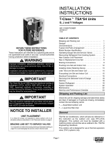
No. Description
1. Cylinder Connection
2. High Side Gauge of Nitrogen Regulator (input)
3. Low Side Gauge of Nitrogen Regulator (output)
4. Output Control Valve
5. Charging Hose Connection on Regulator
6. Pressure Regulator T Handle
7. Leak Testing Gauge Assembly
8. Connection to Refrigeration System
9. Leak Testing Ball Valve Lever
10. Charging Hose Connection on Leak Testing Assembly
11. Charging Hose
12. Charging and Testing Manifold (not included in kit)
13. Low Side Valve on Manifold
14. Low Side Hose (blue)
15. Charging Hose (yellow)
16. High Side R134a 1/4” FL-M x 16mm Economy Coupler
TECHNICAL DATA:
Connection:
• Model # 53001: CGA580 (US)
Pressure Regulator:
• 100 - 4500 PSI (7 - 300 Bar) High side
• 30 – 1000 PSI (2 – 70 Bar) Adjustment range
• Integrated Shutoff Valve
Safety Relief Valve: 725 PSI (50 Bar)
Gauge Diameter: 2 5/8 (68 mm) Not including guard
WARNINGS
• Only use with nitrogen gas (N2).
• The regulator is not to be used with liquid nitrogen.
• Do not modify the regulator. Doing so could result in personal injury.
• Do not over-pressurize the regulator. This could cause leakage, part damage or personal
injury due to bursting of pressure-containing parts.
• Keep the regulator clean and free of oil.
• Do not use a damaged regulator. Except for replacing the gauges, do not attempt to
repair the regulator.

2
• Failure to follow instructions can result in personal injury and/or damage to the equip-
ment.
• Do not install this regulator where service conditions can exceed the specifications of
any applicable local, state, or federal codes and regulations.
• Wear safety glasses and gloves.
REGULATOR CONNECTION AND USE
NOTE: The nitrogen regulator can be used with a charging hose and leak testing gauge
assembly or a charging and testing manifold.
• Make sure the cylinder connection (1) is clean and free from damage.
• Turn the T handle (6) all of the way out (counter clockwise, looking from the bottom).
• Open the output control valve (4) to release any pressure, and then close it.
• Install the nylon gasket or O-ring, if the connection requires one.
• Install the regulator onto the cylinder. Do not over tighten the nut on gasket connections.
• Connect the yellow charging hose (11) from the regulator to the leak testing gauge
assembly, making sure the ball valve connection (9) is closed. (If using a manifold,
connect the yellow charging hose (15) of the manifold to the regulator.)
• Connect the other end of the leak testing gauge assembly (8) to the system.
(If using a manifold, connect the low side hose (14) from the manifold to the system.)
• Slowly open the cylinder valve. The high side gauge (2) should read the cylinder
pressure.
• Adjust the regulator pressure by turning the T handle (6) clockwise until the required
pressure (based on the system’s refrigerant) is shown on the low side (output) (3)
pressure gauge.
NOTE: This is a non-reliving regulator. To adjust the output pressure lower, some
nitrogen will have to be released from the output (e.g. with no hoses connected, turn the
T handle counter-clockwise, then open the output control valve and close it. The output
gauge should read a lower pressure.)
• If using the leak testing gauge assembly, turn the red needle to the required refrigerant
pressure.
Testing Range of Systems
R134a 260 - 320 psi 18 - 22 bar
R404A 405 - 465 psi 28 - 32 bar
R404C 405 - 465 psi 28 - 32 bar
R507 405 - 465 psi 28 - 32 bar
R22 405 - 465 psi 28 - 32 bar
R410A 550 - 610 psi 38 - 42 bar
• Open the output control valve (4) and open the ball valve (9) on the leak testing gauge
assembly for the nitrogen to flow into the system. (If using a manifold, open the output
control valve (4) and the low side valve (13) on the manifold.)
• Make sure the required pressure is available on both gauges. (You may need to turn the
T handle (6) on the regulator to adjust to the required pressure.)
• Once the pressure is equalized (make sure the black needle is aligned with the red
marker on the leak testing gauge assembly) close the ball valve connection (9).
(If using a manifold, close the low side valve (13) on the manifold making note of the
pressure when the valve is closed.)
• Close the output control valve (4) on the regulator
• Disassemble the yellow charging hose (11) from the regulator and leave the system for
a period of time (time is based on the size of the system.)
• After some time, look at the gauge, if there is a leak in the system the pressure will
have dropped from the original setting.
REGULATOR REMOVAL
• Turn the cylinder valve off.
• Relieve the pressure on the regulator by opening the output control valve (4). Both
gauges should read zero.
• Slowly loosen the cylinder connection. There may still be some pressure between the
regulator and cylinder.
• Completely remove the regulator.
• Clean and store the regulator in its box to prevent damage.
53010-AUT-INST
For parts or service, contact the service department: 1-888-825-6989
WARNING: This product can expose you to chemicals including Di (2-ethylhexyl) phthalate, lead and
lead compounds, which are known to the State of California to cause cancer and birth defects or
other reproductive harm. For more information go to www.P65Warnings.ca.gov
/