Page is loading ...

Liquid
Level
Control
Pneumatic Modulevel
®
& APM Controllers
Installation and Operating Manual

48-620 Modulevel Pneumatic Liquid Level Control
R
ead this Manual Before Installing
This manual provides information on Pneumatic
Modulevel
®
& APM Controllers. It is important that all
instructions are read carefully and followed in sequence.
Detailed instructions are included in the Installation sec-
tion of this manual.
Conventions Used in this Manual
Certain conventions are used in this manual to convey
specific types of information. General technical material,
support data, and safety information are presented in
narrative form. The following styles are used for notes,
cautions, and warnings.
NOTES
Notes contain information that augments or clarifies
an operating step. Notes do not normally contain
actions. They follow the procedural steps to which
they refer.
Cautions
Cautions alert the technician to special conditions that
could injure personnel, damage equipment, or reduce
a component’s mechanical integrity. Cautions are also
used to alert the technician to unsafe practices or the
need for special protective equipment or specific
materials. In this manual, a caution box indicates a
potentially hazardous situation which, if not avoided,
may result in minor or moderate injury.
WARNINGS
Warnings identify potentially dangerous situations or
serious hazards. In this manual, a warning indicates an
imminently hazardous situation which, if not avoided,
could result in serious injury or death.
Safety Messages
Follow all standard industry procedures for servicing elec-
trical equipment when working with or around high
voltage. Always shut off the power supply before touch-
ing any components.
WARNING! Explosion hazard. Do not connect or dis-
connect equipment unless power has been switched off or
the area is known to be non-hazardous.
L
ow Voltage Directive
For use in Installation Category II. If equipment is used
in a manner not specified by the manufacturer, protec-
tion provided by the equipment may be impaired.
Notice of Trademark, Copyright, and Limitations
Magnetrol and Magnetrol logotype, and Modulevel are
registered trademarks of Magnetrol International.
Copyright © 2019 Magnetrol International,
Incorporated. All rights reserved.
Performance specifications are effective with date of
issue and are subject to change without notice.
Magnetrol reserves the right to make changes to the
product described in this manual at any time without
notice. Magnetrol makes no warranty with respect to
the accuracy of the information in this manual.
Warranty
All Magnetrol mechanical level and flow controls are war-
ranted free of defects in materials or workmanship for five
full years from the date of original factory shipment.
If returned within the warranty period; and, upon factory
inspection of the control, the cause of the claim is
determined to be covered under the warranty; then,
Magnetrol will repair or replace the control at no cost to
the purchaser (or owner) other than transportation.
Magnetrol shall not be liable for misapplication, labor
claims, direct or consequential damage or expense arising
from the installation or use of equipment.
There are no other warranties expressed or implied,
except special written warranties covering some
Magnetrol products.
Quality Assurance
The quality assurance system in place at Magnetrol guar-
antees the highest level of quality throughout
the company. Magnetrol is committed to providing full
customer satisfaction both in quality products and quality
service.
The Magnetrol quality assurance system is registered to
ISO 9001 affirming its commitment to known interna-
tional quality standards providing the strongest assurance
of product/service quality available.

Table of Contents
1.0 Introduction
1.1 Principle of Operation ..............................................5
1.2 Operating Cycle ........................................................5
1.3 Description ...............................................................6
1.3.1 Controller Action ...........................................6
1.3.1.1 Proportional Control...............................6
1.3.1.2 Transmitter .............................................6
1.3.1.3 Transmitter/Receiver Controller..............6
1.3.1.4 Proportional Plus Integral Control ..........6
1.3.1.5 Differential Gap......................................7
1.3.2 Controller Options.........................................7
1.3.2.1 Direct or Reverse Action .........................7
1.3.2.2 Electric Limit Switches............................7
1.3.3 Mounting Arrangements ................................7
1.3.3.1 Flanged Top P51, P61 and P62
Displacer Models ....................................7
1.3.3.2 Top Mounted APM-131 .........................7
1.3.3.3 External Cage P53, P55, P63, P64, P65,
P66, P71 and P72 Displacer Models.......7
1.3.3.4 External Cage APM-W251,
APM-W254 and APM 291.....................8
1.3.3.5 Side Mounted P68 Float Model..............8
2.0 Installation
2.1 Unpacking ................................................................8
2.1.1 P51, P61, P62 and APM-131 Models............8
2.1.2 P53, P55, P63, P64, P66,
P71, P72, APM-W251, APM-W254
and APM-W291 Models................................8
2.1.3 P68 Models....................................................8
2.1.4 Transmitter – Receiver Controller Units.........9
2.1.5 Specifications..................................................9
2.2 Mounting................................................................10
2.2.1 Top Mounted Models – P51, P61 & P62 ....11
2.2.2 External Cage Models – P53, P55, P63,
P64, P65, P66, P71 & P72 ..........................11
2.2.3 Side Mount Models – P68 ...........................12
2.2.4 Transmitter – Receiver Models .....................12
2.3 Calibration..............................................................13
2.3.1 Proportional Controllers...............................13
2.3.1.1 Calibration Chart Instructions ..............15
2.3.2 Reset Controllers..........................................16
2.3.3 Transmitters .................................................17
2.3.4 Receiver Controllers .....................................18
2.3.5 Differential Gap ...........................................18
2.3.6 Interface Models...........................................19
2.3.7 Electric High/Low Limit Switches................20
2.3.7.1 Electrical Ratings...................................20
2.3.7.2 Wiring Information ..............................20
2.3.7.3 Adjustment Procedure...........................21
2.4 Field Modifications and Adjustments......................21
2.4.1 Changing Controller Action.........................21
2.4.2 Proportional Band Models to
Differential Gap ...........................................21
2.4.3 Pneumatic-to-Current (P/I) Converter .........21
2.4.4 Reset Installation..........................................22
2.4.5 Reset Cleaning .............................................23
2.4.6 Disabling Reset ............................................23
3.0 Reference Information
3.1 Troubleshooting ......................................................24
3.1.1 Installation ...................................................24
3.1.2 Calibration ...................................................24
3.1.3 Operation.....................................................25
3.2 Specifications ..........................................................27
3.2.1 Standard Flanged Top and Flanged Cage
Displacer Models P62, P63, P64, P65
and P66 Dimensional Specifications ............27
3.2.2 High Pressure Flanged Top and
Flanged Cage Displacer Models P51, P53
and P55 Dimensional Specifications ............28
3.2.3 Standard Sealed Cage Displacer Models
P71 and P72
Dimensional Specifications...........................29
3.2.4 Models APM-131, APM-W251,
APM-W254 and APM-W291 Dimensional
Specifications................................................30
3.2.5 Standard Side Mount Float Models P68
Dimensional Specifications...........................31
Modulevel
®
Pneumatic
Liquid Level Control
48-620 Modulevel Pneumatic Liquid Level Control

3.3 Replacement Parts...................................................32
3.3.1 Model P68 Threaded and Flanged
Parts Identification .......................................32
3.3.1.1 Model P68-2F2A Threaded 3" NPT.....33
3.3.1.2 Model P68-2H3A, P68-2H4A and
P68-2H5A 4" Flanged ..........................33
3.3.2 Model Series P6x Parts Identification ...........34
3.3.2.1 Series P61, P62, P63, P64,
P65, P66, P71 and P72.........................36
3.3.3 Series P51, P53 and P55 Parts
Identification................................................37
3.3.3.1 Series P51, P53 and P55 .......................38
3.3.4 Model APM-131 Parts Identification ...........39
3.3.4.1 Model APM-131 Part Number ...............39
3.3.5 Models APM-W251, APM-W254
and APM-W291 Parts Identification............40
3.3.5.1 Models APM-W251, APM-W254
and APM-W291 Parts Numbers .............41
3.3.6 Controller Parts............................................42
3.3.6.1 Controller Replacement
Assemblies Parts Identification ..............43
3.3.6.2 Tubing Kit 89-8501-015
@ 3–15 and 6–30 psig ..........................44
3.3.6.3 Nozzle Lever Kit 89-8501-002
@ 3–15 and 6–30 psig ..........................44
3.3.6.4 Carriage Assembly Kit
89-8501-003 @ 3–15 and 6–30 psig ....44
3.3.6.5 Feedback Assembly Kit
89-8501-005 @ 3–15 and 6–30 psig ....45
3.3.6.6 Gasket Kit for Relay Assembly
89-8501-014 @ 3–15 and 6–30 psig ...45
3.3.6.7 Additional Replacement Parts ...............45
3.3.7 Reset Replacement Parts...............................46
3.3.7.1 Reset Replacement Assemblies ..............47
3.3.7.2 Replacement Kits (Reset Valve,
O-Ring and Offshore)...........................47
3.3.8 Receiver Controller Parts..............................48
3.3.8.1 Receiver Controller Replacement
Assemblies.............................................48
3.3.9 Transmitter Mounted Receiver
Controller Parts............................................49
3.3.9.1 Transmitter Mounted Receiver
Controller Replacement Assemblies ......49
3.3.10 Pneumatic Modulevel Replacement
Head Kits..............................................50
3.4 Model Numbers......................................................52
3.4.1 Standard Flanged Top and
Flanged Cage Displacer Models....................52
3.4.2 High Pressure Flanged Top and
Flanged Cage Displacer Models....................54
3.4.3 Standard Sealed Cage Displacer Models .......56
3.4.4 Standard Side Mount Displacer Models .......58
3.4.5 APM Pneumatic Control Models.................59
Table of Contents (continued)
Modulevel
®
Pneumatic
Liquid Level Control
48-620 Modulevel Pneumatic Liquid Level Control

48-620 Modulevel Pneumatic Liquid Level Control
5
1.0 Introduction
Modulevel pneumatic controls are displacement actuated
level sensors that provide output signals in direct propor-
tion to changes in liquid level.
Simple modular design and proven magnetic coupling
make Modulevel controls versatile, highly stable, vibration
resistant and adaptable to extremes of temperature and
pressure.
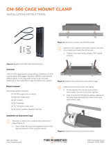
1.1 Principle of Operation
The key elements of the Modulevel
pneumatic control are the magnetic
coupling, which allows the controller
to be mechanically isolated from the
sealed sensing unit; the range spring,
which converts the change in buoyancy
force on the displacer into motion; and
the controller head, which provides a
modulated pneumatic signal in direct
proportion to the motion of the spring.
1.2 Operating Cycle
The result of liquid level changes in
the vessel is a change in the buoyancy
force acting on the displacer and in the
load on the spring from which the dis-
placer is suspended. As the spring
extends or compresses with the change
in load, an attraction ball attached to
the spring via a stem assembly moves
within the enclosing tube.
A magnet encircling the enclosing
tube follows the attraction ball, trans-
ferring the motion to a rotating cam,
which in turn operates a flapper
against a nozzle which increases or
decreases the pressure within the pneu-
matic relay. The output pressure signal
can be used in a variety of ways to
operate a control valve or signal
alarms, indicators, process controls or
other devices.
0
100
Pilot Nozzle
Flapper
Cam
Attraction Ball
Magnet
Enclosing
Tube
Indicator
Zero Adjustment
Proportional Band
Adjustment
Actuating
Lever
Set Point
Adjustment
Reset
Valve
Feedback
Bellows
Chamber
Relay
Filter
Regulator
Control
Valve
Orifice
Check
Valve
Reset
Bellows
Range
Spring
Displacer
OUTPUT SUPPLY
Proportional
Band Spring
Supply Pressure Output pressure Pilot Pressure Reset Pressure
Figure 1

6
48-620 Modulevel Pneumatic Liquid Level Control
1.3 Description
Modulevel pneumatic instruments are available for a
variety of functions to handle different application
requirements.
1.3.1 Controller Action
1.3.1.1 Proportional Control
Proportional control instruments are used to maintain
the level in a tank within a predetermined band. The
output from the Modulevel head controls the opening
and closing of a valve to control the increase or
decrease of the liquid flow through the vessel.
1.3.1.2 Transmitter
Transmitters provide a pneumatic signal proportional
to the level of a liquid. The signal can be fed to a
variety of devices as the application requires.
1.3.1.3 Transmitter/Receiver Controller
There are two devices in this version. The transmitter
senses level directly at the vessel, and provides a pneu-
matic signal to the receiver/controller. The receiver/
controller operates in the same manner as a direct
connected level device, such as a proportional con-
troller, which allows varying the proportional band
and level set point. This unit may be mounted either
integrally with the transmitter, or at a more
convenient remote location.
1.3.1.4 Proportional Plus Integral Control
Proportional plus integral control instruments (i.e.,
with reset) operate in the same manner as the propor-
tional unit with one major difference. The offset
between the desired level and the actual level is elimi-
nated, thus maintaining the level at a point rather
than within a band.

48-620 Modulevel Pneumatic Liquid Level Control
7
1.3.1.5 Differential Gap
A differential gap instrument provides two distinct outputs,
either opened or closed. One distinct output value is
obtained when the level exceeds the upper switching point.
This value remains constant until the level decreases below
the lower switching point. At this time the controller
changes to another distinct output value. The new value
remains constant until the level again rises above the upper
switching point causing the output value to return to the
first output value. The distance between the two switching
points is called the differential gap.
1.3.2 Controller Options
1.3.2.1 Direct or Reverse Action
Direct acting controllers provide an output signal that
increases with level increase. Reverse acting controllers
provide an output signal that decreases with level increase.
1.3.2.2 Electric Limit Switches
Electric limit switches allow high and low level alarms to be
added to any of the pneumatic instruments described above.
1.3.3 Mounting Arrangements
1.3.3.1 Flanged Top P51, P61 and P62 Displacer Models
When mounting inside the tank is possible, flanged top
models are the answer (Figure 2). They are used extensively
in interface control applications where nonstandard displac-
ers become necessary. An adjustable stainless steel displacer
hanger cable is also available. Top mounting models are
directly interchangeable with the external cage models.
1.3.3.2 Top Mounted APM-131
When mounting inside the tank is possible, threaded
top models are the answer. An adjustable stainless steel
displacer suspension cable is provided as standard.
1.3.3.3 External Cage P53, P55, P63, P64, P65, P66, P71 and
P72 Displacer Models
External cage models (Figure 3) can be easily isolated from
the process to simplify maintenance and inspection
operations. The in-line design eliminates the need for
specifying "right hand" or "left hand". Any mounting
position is possible by rotating the instrument head. A
variety of models are available including sealed or flanged
cage with either side/side or side/bottom connections.
Carbon steel and stainless steel models are available.
Figure 2
Top Mount
Figure 3
P6X External
Cage
Figure 4
APM External Cage
Locking
Screw

8
48-620 Modulevel Pneumatic Liquid Level Control
1.3.3.4 External Cage APM-W251, APM-W254, APM-W291
Water Column external cage models (Figure 4) can be
easily isolated from the process to simplify maintenance
and inspection operations. Sight glass and Try-cock
tappings are provided.
1.3.3.5 Side Mounted P68 Float Model
Side mounted models (Figure 5) are ideally suited for
narrow level range applications. Carbon steel models are
available with either a 3" NPT threaded body or a 4"
flanged connection.
2.0 Installation
2.1 Unpacking
After unpacking, inspect all the components to see that no
damage has occurred during shipment. Care should be taken
not to bend the displacer stem or enclosing tube during
unpacking or installation.
Next, open controller case and remove magnet hold down and
nozzle lever retainers. Examine internal controller components
for any obvious damage or loosened parts. Check all air con-
nections to make certain they are free of any foreign matter.
2.1.1 P51, P61, P62 and APM 131 Models
Top mounting Modulevel units are shipped from the factory
with the controller and displacer removed from the head
assembly and packed separately in the same carton or crate.
2.1.2 P53, P55, P63, P64, P66, P71, P72, APM-W251,
APM-W254 and APM-W291 Models
All cage type Modulevel units are shipped with the controller
removed from the chamber assembly and packed separately
in the same carton or crate.
A strap and wire assembly retains and protects the displacer
within the chamber during shipment. The assembly must be
removed through the bottom connection before start-up.
Caution: If reshipping to another location, displacer assembly must
again be secured using same strap and wire assembly.
2.1.3 P68 Models
The side mounting Modulevel units are shipped with the
controller and float and stem assembly removed from the
body and are packed separately in the same carton or crate.
After unpacking, inspect all components to see that no
damage has occurred during shipment.
Figure 5

48-620 Modulevel Pneumatic Liquid Level Control
9
2.1.4 Transmitter — Receiver Controller Units
Dual head receiver controller models may be supplied to
be integrally mounted to the top mounting or external
cage style Modulevel controls or to be remotely mounted
away from the Modulevel controls. Units supplied with
top mounting Modulevels may be shipped assembled and
connected to the transmitter head or separately for field
assembly. External chambered units will have the receiver
controller head connected to the transmitter head, but sep-
arate from the chamber. Any heads shipped unassembled
from the Modulevel will be packed in the same carton or
crate as the control. Handle controllers carefully to avoid
damage to the airline piping.
2.1.5 Specifications
Process pressure
Up to 4265 psig at +100 °F
(Up to 318 bar at +38 °C)
Process temperature
-150 to +700 °F
(-101 to +371 °C)
Stainless steel chamber and bolting
required for temperatures below
-20 °F. (Consult factory).
Specific gravity range Minimum: 0.23 Maximum: 2.20
Interface detection
Minimum difference of 0.10 specific
gravity between liquids
Process connections NPT, Socket Weld or Flanged
Instrument quality air (clean and dry)
Supply pressure Regulated to 5 psig (.3 bar)
above maximum output.
Output
Proportional &
3–15 psig, 6–30 psig
signal
transmitter
pressure
Differential gap 0–20 psig or 0–35 psig
Visual Indicator % Span
Level range & proportional
Limited only to displacer length. From
band adjustment inches to 10 feet (3 meters).
Air consumption
3 SCFH at 9 psig output
6 SCFH at 15 psig output
100 cu. in. output volume in 3.2 sec.
Response speed upon an output pressure increase
from 3–15 psig.
Trim: 304 or 316 SS
Wetted parts Spring: 316 SS or inconel
Chamber: Carbon steel or 316 SS
Control action Direct or reverse
Proportional control,
Modes of operation Differential gap,
Transmitter
Housing (standard) NEMA 1, 2, 3, and 3R
Max. voltage: 120 VAC/VDC
Limit switch ratings
Max. resistive load: 10 VAC/VDC
Max. current:
1
⁄4" amp switching
1 amp holding
Description Specification

10
48-620 Modulevel Pneumatic Liquid Level Control
2.2 Mounting
Before assembling control to vessel, check with spirit level
to ensure that the mounting flange is horizontal. Proper
operation of the control depends on the Modulevel con-
troller being within 3° of vertical in all directions. The
head assembly with sensing components is installed first,
then the controller is placed carefully over the enclosing
tube, rotated to desired position, and then locked in place
by securely tightening the locking screw. Check to be cer-
tain the controller magnet can move smoothly throughout
its actuating stroke without binding against the enclosing
tube. If binding occurs, loosen the slot-head screw, reposi-
tion magnet and tighten screw.
Caution: The spring and stem assembly that protrudes below
the mounting flange on a top mounted Modulevel is very
fragile. DO NOT handle this assembly or place control so
that any amount of force is exerted on the spring and stem
assembly. Proper operation of the control requires that
this assembly is not damaged or bent.
Caution: Displacer spring and stem are fragile. Do not drop dis-
placers into tank. Hand feed cable into position to avoid
bending stem.
Caution: All Modulevel units are shipped from the factory with the
enclosing tube tightened and the controller head set
screw locked to the enclosing tube (see figure 2, page 7).
Failure to loosen the set screw prior to repositioning the
supply and output connections may cause the enclosing
tube to loosen, resulting in the possible leakage of the
process liquid or vapor.
NOTE: Since controller is rotatable through 360°, it is important to
make certain controller locking screw is tight before installing
air or gas connections.
The supply and output air or gas connections provided on
the Modulevel are
1
⁄4" NPT. These connections are clearly
indicated on the side of the controller. The filter-regulator
(if furnished) is to be set to deliver a 20 psig supply
pressure to a 3–15 psig output controller or a 35 psig sup-
ply pressure to a 6–30 psig output controller. The main
supply pressure to the regulator should be between 25 and
250 psig (or 40 and 250 psig) and connected to the inlet
side of the regulator. In order to protect the instrument
from contaminants, clean, dry air or gas must be used as
a supply medium.
Caution: Do not overtighten fittings in supply and output connec-
tions. Overtightening may crack the housing outlets.

48-620 Modulevel Pneumatic Liquid Level Control
11
Caution: Operation of all buoyancy type level devices should be
done in such a way as to minimize the action of dynamic
forces on the float or displacer sensing element. Good
p
ractice for reducing the likelihood of damage to the con-
trol is to equalize pressure across the device very slowly.
2.2.1 Top Mounted Models – APM-131, P51,
P61, and P62
Check to be certain there are no tubes, or other
obstacles in the vessel to interfere with the
operation of the displacer. Stillwells are recom-
mended where a continuous agitation or
motion is prevalent.
NOTE: Stillwell installation should be checked to be cer-
tain tube (or pipe) is plumb. An out-of-plumb still
well may restrict displacer movement. Also,
ensure that the stillwell is vented at the top to
allow the liquid to rise in the tube with level
movement.
Figure 6 shows a typical piping installation for
a top mounted unit to a tank or vessel.
2.2.2 External Cage Models – APM-W251, APM-
W254, APM-W291, P53, P55, P63, P64,
P65, P66, P71 and P72
The external cage type Modulevel should be
mounted on the side of the tank or vessel with
either side/side connections or side/bottom
connections, as shown in Figure 7. Mid-range
mark on control cage should be aligned to
correspond with desired control level in tank
or vessel.
NOTE: It is essential that the external cage assembly be
mounted plumb to ensure frictionless operation
of its internal displacer.
It is recommended that isolation valves be
installed in each equalizing line to the cage as
well as a drain valve at the bottom of the
chamber (refer to Figure 7). Equalizing lines
should be sized at least as large as connections
provided on the cage.
Controller
Displacer
Liquid
L
evel
Control
Valve
Output
Pressure
Supply
Pressure
Filter Regulator
Figure 6
Top Mounted Units
Controller
Liquid
Level
Control
Valve
Output
Pressure
Supply
Pressure
Filter Regulator
Figure 7
External Cage Units

12
48-620 Modulevel Pneumatic Liquid Level Control
Figure 8
Transmitter – Receiver Controller Units
2.2.3 Side Mount Models – P68
Side mount controls mount horizontally to any
tank or vessel through a flanged or threaded pipe
connection. Refer to the illustrations on page 31 for
threaded nozzle and flanged mounting dimensions. It is
essential that the control be mounted horizontal.
N
OTE: To allow the 3" float to pass through the nozzle, the nozzle
bore diameter must not be less than 3.00" schedule
40 pipe size.
2.2.4 Transmitter – Receiver Models
Check installation considerations described for either top
mount or cage type mounting units and apply those
appropriate for joint installations with receiver controllers.
Figure 8 shows a typical piping installation of a receiver
controller to a top mounted transmitter type Modulevel
control. A chamber type Modulevel installation would be
the same, with obvious physical differences on a side of
tank installation. Piping for a separate receiver controller
would be done in a similar manner except unit would be
remotely wall or panel mounted in a control house or
installed at or near the control valve.
NOTE: Refer to page 49 for detailed assembly of receiver controller to
a transmitter type Modulevel controller.
Check alignment of mounting bracket for receiver con-
troller to be certain top surface of collar is flush with top
head assembly so that tops of both controller heads are in
the same plane.
NOTE: Alignment of controllers is required only to
suit factory furnished piping and fittings
between controllers. If mounting is to be
accomplished using any other method,
including remote installations, all piping
must be provided by customer.
All pneumatic (piping) connections should
have threaded joints, sealed with Teflon thread
tape or pipe compound suitable for use on
pneumatic lines;
1
⁄4" pipe size or
5
⁄16" O.D. tubing is recommended.
Transmitter
Receiver Controller
Displacer
Liquid
Level
Control Valve
Remote Mounted
Receiver Recorder
(or Indicator)
Output
Pressure
Supply Pressure
Filter Regulator

48-620 Modulevel Pneumatic Liquid Level Control
13
2.3 Calibration
2.3.1 Proportional Controllers
Each Modulevel control is calibrated at the factory
before shipment. Specified actions have been preset
and all scales have been calibrated. Each unit is cal-
ibrated at 1.0 SG and for use of the full length of
the displacer. However, upon receipt of the instru-
ment the following calibration and adjustment
procedure is recommended for all controllers:
1. Check supply pressure:
After appropriate piping has been made to the
filter regulator and output connections, and
checked for leaks, the supply gauge, shown in
Figure 9, should indicate 20 psig (35 psig for
6–30 psig controllers).
2. Check control action:
To check controller action, manually rotate the
magnet carriage to simulate an increase in level.
Note the direction of the output pressure
change. (Rising level will increase the output
pressure on direct acting controllers.
Conversely, rising level will decrease the output
pressure on the reverse acting controllers.) The
action cam and level adjustment knob must
both indicate the same action
Should it be required to change the controller
action, the action cam can be manually rotated
180° to the desired action. Make certain that
the notch in the cam is set into the tab of the
pilot nozzle assembly. Cam actions are clearly
marked on the cam face as indicated in Figure
10. A zero adjustment will normally be required
upon change.
NOTE: It is also important that the level adjustment knob
scale action be compatible with the cam action. The
level adjustment knob scale is printed DIRECT
ACTION on one side and REVERSE ACTION on the
other. To change scales, remove level adjustment
knob and turn over level scale. Replace knob with
same orientation on shaft as before removal.
3. Check level indicator zero setting.
A level indicator is furnished with each
Modulevel pneumatic controller and is conve-
niently located inside the instrument case. The
level indicator, shown in Figure 11, indicates
the level as a percentage of the displacer length.
Figure 9
Proportional Controller with Reset
1
2
3
4
5
6
7
14
1
3
9
1
0
11
12
8
Proportional band adjustment knob
Zero adjustment screw
Supply pressure gauge
Level adjustment knob
Magnet carriage
Level indicator
Output pressure gauge
Figure 10
Pilot Nozzle Assembly
Proportional Control
Differential Gap Control
1
3
4
5
6
7
8
9
10
11
12
13
14
2
Output connection
Supply connection
Action cam
Relay
Orifice cleanout plunger
Flapper nozzle assembly
Reset adjustment knob

Figure 11 shows a liquid specific gravity of .8 with a corre-
sponding level reading of 45% and a process temperature of
approximately +250 °F (+121 °C). An adjustment is
provided on the level indicator to calibrate the pointer and
indicator scale when control is at operating temperature.
NOTE: Consult factory for procedure to calibrate level indicator if precise
reading is required.
With the system at operating temperature, adjust level of
process liquid in the tank (or vessel) to allow the displacer to
"hang-free" above the liquid. The pointer on the level indi-
cator should read zero percent on the indicator scale. Refer
to Figure 11. To adjust, loosen calibration adjustment screw
at the top of the indicator scale and move scale until the
pointer is aligned to zero. Retighten adjustment screw.
4. Adjust the proportional band and the level:
(The proportional band is the span setting.) The
proportional band adjustment knob, located adjacent to
the pilot nozzle assembly, sizes the proportional band as a
percentage of the displacer length. When the proportional
band is set at 5, the output range will correspond to 50%
of the total displacer length. For example; on a control
with a 14" displacer, a proportional setting of 5 will
result in full output range over a 7" level change.
(The level adjustment is the control set point.) The
level adjustment knob, located just below the supply
pressure gauge, positions the midpoint of the propor-
tional band on the displacer. For example; on a control
with a 14" displacer, a level setting of 5 will locate the
midpoint of the proportional band 7" from the bottom
of the displacer.
The proper method for calibrating a proportional controller
follows:
Calibration example: 1.00 specific gravity liquid, 50%
proportional band desired, 50% level adjustment desired,
3 –15 psig output, direct action.
4.1 Set the pointer on magnet carriage slide bar to 1.00
specific gravity.
4.2 Set both the level and proportional band knobs to
5 (or 50%) on each scale.
4.3 Move the magnet carriage by hand until the pointer reads
50% of displacer length, hold accurately at this position.
4.4 Adjust the zero screw until the output pressure gauge reads
9 psig.
4.5 Move the magnet carriage pointer to 75% displacer length.
Output pressure should read 15 psig.
NOTE: If required, small readjustments can be made at the level and
proportional band knobs.
14
48-620 Modulevel Pneumatic Liquid Level Control
0
20
40
60
100
8
0
1.1
1.0
.90
.
80
.70
.60
.50
S
P.
G
R.
LEVEL
DISPLACER
LENGTH
%
100F
400
700
T
E
M
P
C
alibration Scale
A
djustment Screw
Pointer
Magnet
Carriage
Slide Bar
Figure 11
Level Indicator
Level = 2.8
(72)
9.10
(231)
PB = 4.2
(107)
PB = 5
Level = 5
0.7
(18)
Level = 7.0
(178)
3.50
(89)
3.50
(89)
PB = 7.0
(178)
PB = 3
Level = 2
Inches (mm)
Figure 12
Proportional Band & Level

48-620 Modulevel Pneumatic Liquid Level Control
15
5. Set the level and proportional band for your applica-
tion. Use calibration chart and instructions given in
Figure 13 to select the level and proportional band
dial settings based on the specific gravity of liquid to
be measured.
5.1 Set the magnet carriage slide bar to the correct liquid
specific gravity for your application.
5.2 To check the zero adjustment, bring the liquid level
up until the level indicator reads the desired level set
point. Set the zero adjustment screw until output
pressure gauge reads 9 psig.
6. To check the level and 3–15 settings:
Adjust the liquid level until the level indicator reads
the low value of the desired span range in terms of %
of displacer length. The output pressure should read
3 psig. Adjust the liquid level to the maximum value
of the desired span range in terms of % of displacer
length. The output pressure should read 15 psig.
2.3.1.1 Calibration Chart Instructions
(for operating at SG other than 1)
To set level:
1. Determine the desired level set point in terms of %
of displacer length.
2. Trace desired level from left to right to the specific
gravity line for the product.
3. Trace down from where the two lines intersect to the
appropriate dial setting.
4. Adjust the level setting on the controller to this value.
To set proportional band:
1. Determine the desired proportional band in terms of
% of displacer length.
2. Trace from left to right to the specific gravity line for
the product.
3. Trace down from where the two lines intersect to the
appropriate dial setting.
4. Adjust the proportional band setting on the con-
troller to this value.
NOTE: If required, small readjustments can be made at the level and
proportional band knobs. To increase proportional band, the
band knob is turned to a higher number. For best control, it is
normally desirable to set the proportional band at the narrowest
setting which will not produce cycling. To raise the level, the
level adjustment knob is rotated in the desired direction indi-
cated on the dial face.
Figure 13
Dual Setting for Level & Proportional Band

16
48-620 Modulevel Pneumatic Liquid Level Control
2.3.2 Reset Controllers
Each Modulevel control is factory calibrated before ship-
ment for 30% span and minimum reset. The following
calibration and adjustment procedures are recommended
for all reset controllers:
1. Check to make sure the reset knob is fully counter-
clockwise.
NOTE: This effectively reduces the reset time to a minimum, but does
not completely eliminate reset.
2. Follow the calibration steps 1 through 4 for propor-
tional controllers beginning on page 13.
3. Use the calibration chart, Figure 13, to select the level
and proportional band initial settings, based on the
specific gravity of the liquid to be measured.
4. Adjust the reset clockwise until stable control is
maintained.
5. Set the magnet carriage slide bar to the correct liquid
specific gravity for your application.
The following adjustment procedure can be used to cali-
brate the reset controller to your specific application by
adjusting the liquid levels:
Alternate method to calibrate reset
1. Set the proportional band index to 10. (This setting is
comparable to 100% for S.G. equal to 1.0.)
2. Turn the reset dial fully counterclockwise.
3. Slowly open downstream and upstream manual control
valves and close by-pass valve.
4. Adjust control point to desired level by means of level
adjustment knob.
5. Narrow the proportional band until a cyclic control
condition occurs. Then, widen the proportional band
by approximately 20% to give stable control.
6. Decrease the reset time until a cyclic condition again
occurs. Then, increase the reset time until stable con-
trol is maintained.
7. Normally the narrowest proportional band and fastest
reset timing required to obtain stability will produce
the optimum control. It is recommended that a
momentary load upset is then produced to further
check system stability and response. (Load can be
imposed by moving magnet carriage manually.)
NOTE: Allow system enough time to stabilize after each adjustment.

48-620 Modulevel Pneumatic Liquid Level Control
17
2.3.3 Transmitters
For Modulevel transmitters, the output signal is directly
proportional to the level on the displacer. To calibrate a
Modulevel transmitter:
1. Follow steps 1 through 3 for Proportional Controllers
(page 13).
2. Set the zero adjustment knob to a vertical position
(arrow straight up at 12 o’clock).
NOTE: Don't confuse the zero adjustment knob with the zero screw
located on top of the pilot nozzle assembly.
3. Set the pointer on the magnet carriage slide bar to the
process specific gravity.
4. Set the specific gravity knob to the process specific
gravity.
NOTE: The specific gravity adjustment sets the span for the unit.
5. Rotate the magnet carriage on the visual level indica-
tor by hand, until the pointer reads 50% of displacer
length.
6. While holding the magnet carriage at 50%, adjust the
zero screw to obtain 9 psig output pressure for 3–15
psig units (or 18 psig output for 6–30 units).
7. Rotate the magnet carriage by hand to 0% displacer
length. The output should be 3 psig. If it is not,
slightly adjust the specific gravity knob to obtain
3 psig output pressure.
8. Rotate the magnet marriage by hand to 100%
displacer length. The output pressure should be
15 psig. If it is not, slightly adjust the specific gravity
knob to obtain 15 psig output pressure.
9. Recheck the midpoint (50% displacer). Adjust the
zero screw to obtain 9 psig output pressure if it
has changed.
10. Recheck the zero output and full scale output.
The Modulevel transmitter has now been calibrated
using the level indicator to simulate process level. If a
more precise calibration to the actual process conditions
is required, the above procedure can be performed
using actual process level on the displacer to set the
calibration points.

18
48-620 Modulevel Pneumatic Liquid Level Control
2.3.4 Receiver Controllers
1. Connect the output from the transmitter to the receiver
controller input at the rear of the receiver controller
housing.
2. Connect a separate supply and output at the right side
of the receiver controller housing.
3. Set the proportional band knob at 100 (100%).
4. Set the direct acting knob at 5 (50%). The output
gauge should read the same as the transmitter output.
If it does not, adjust the zero knob on the receiver
controller until both readings are the same.
To increase or decrease span distance, turn the propor-
tional band knob to the setting desired, for example,
50 = 50% of span. To move the span mid-point, turn
the direct action knob to the setting desired.
For a reverse acting output, from a direct acting
transmitter output, invert the spring/bellows assembly
so that the bellows are on top. Recalibrate as described
above.
Remove the direct acting indicator plate, and turn it to
reverse acting. Recalibrate as described above.
If reset is included with the receiver controller, turn the
reset knob fully counterclockwise and calibrate as
described above.
Adjust reset clockwise until stable control is maintained.
2.3.5 Differential Gap
1. Follow steps 1 through 4 of Proportional Controller
Calibration section. Refer to pages 13 through 17,
except the output is 0–20 psig or 0–35 psig with
no mid-range adjustment.
NOTE: When checking the control action for a direct action differen-
tial gap unit, set the cam to reverse action; for a reverse action
differential gap unit, set cam to direct action.
2. Check that the pilot nozzle assembly is set up for dif-
ferential gap operation. Figure 10 on page 13 illustrates
the pilot nozzle flapper configurations used for the two
control modes, proportional and differential gap. If
your unit is already set up for differential gap mode,
proceed to step 3.

48-620 Modulevel Pneumatic Liquid Level Control
19
To change the control mode:
a. Loosen the tube clamp screw.
b. Remove the zero screw from the pilot nozzle assembly.
c. Remove both screws and top plate from the pilot
nozzle assembly.
d. Flip the pilot nozzle assembly 180° and install screws
with top plate in position.
e. Install the zero screw in the pilot nozzle assembly.
f. Rotate the tube clamp to horizontal and tighten the
tube clamp screw. The cam follower should now rest
on the action cam. If it does not, readjust bracket
without crimping the tube.
NOTE: Make sure the tube is not kinked and does not interfere with
the carriage and the nozzle lever.
g. Change the controller action. For direct action, set
the cam to reverse acting; for reverse action, set the
cam to direct acting.
3. Check zero output. Set level adjustment knob to 5 or
vertical position. Set proportional band knob to 3. Place
level indicator at 35% position (65% position for
reverse action units). Adjust zero screw to get supply
pressure value output; then, slowly readjust the zero
screw until output suddenly decreases to zero.
4. Check 20 psig or 35 psig output. Slowly move the
attraction sleeve to 65% (35% for reverse action units),
at which point the output should suddenly rise to
supply pressure. If not, adjust the proportional band
knob until it does.
5. Set the level and proportional band for your application.
2.3.6 Interface Models
For an interface application, the Modulevel has been
factory precalibrated to operate in liquids with specific
gravities supplied by the customer. The displacer is weight-
ed to obtain a zero (3 psig or 6 psig signal) with
the displacer fully submerged in the lighter liquid only
[15 psig or 30 psig with displacer covered with the heavier
fluid]. The indicator arrow should be set to the difference
between the two specific gravities of the liquids.
Follow the procedures given for installation and calibration
of proportional controllers. Refer to pages 13 through 17.
Keep in mind that the "hang–free" or zero setting
is obtained with the displacer fully submerged in the
lighter liquid, and completely uncovered by the interface
(heavier liquid).

20
48-620 Modulevel Pneumatic Liquid Level Control
As is indicated in the Calibration section for proportional
controllers, the signal should be at 9 psig or 18 psig out-
put with the interface level at the control set point
(level knob setting) on the displacer. Because of the reduced
displacer motion for interface applications, the proportional
band should be set as wide as possible, with a minimum
of 50%.
2.3.7 Electric High/Low Limit Switches
The Pneumatic Modulevel is available with optional built-
in, adjustable electric high/low level limit switching. This
economical, optional feature is well-suited to numerous
applications where a combination pneumatic control and
electric switch actuation is desired.
The Pneumatic Modulevel is used to pneumatically posi-
tion a diaphragm-type feedwater control valve in response
to water level changes in the steam drum. The convenient
addition of electric limit switching provides economical
high and low level alarm indication. These switches are
not intended for primary control purposes.
NOTE: Not suitable for Class I, Div. 1 applications.
2.3.7.1 Electrical Ratings
Each reed switch carries the following electrical
ratings:
Maximum voltage...........................120 VAC or 120 VDC
Maximum resistive load ..........................10 VAC or VDC
Maximum current ...........................
1
⁄4 ampere switching,
1 ampere holding
NOTE: For lamp or capacitive applications, the reed switches are
rated six (6) watts maximum.
2.3.7.2 Wiring Information
Each reed switch assembly is wired at the factory and
furnished with number-coded, 24.00 inch long sili-
cone rubber insulated copper lead wires. Each reed
switch is SPDT in operation. Standard wiring follows:
High level reed switch
No. 5 lead is common
No. 6 lead energizes at high level
No. 4 lead de-energizes at high level
Low level reed switch
No. 2 lead is common
No. 3 lead energizes at low level
No. 1 lead de-energizes at low level
Figure 14
/