
Electric
switch mechanisms
and housings
Installation and Operating Manual
Series B, C, D, F, O, Q, R,
S, U, W, X, 8 and 9

2
PRINCIPLE OF OPERATION
Pivot
Return
Spring
Process
liquid
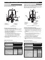
Figure 1
Rising level
Figure 2
Falling level
Process
liquid
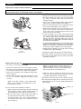
Figures 1 & 2 illustrate the simple, reliable operating prin-
ciple of a float level switch. Switching action is obtained
through the use of a magnetic sleeve (4) and a float (3), dis-
placer or flow sensing element and a switching mecha-
nism (2). These two basic component assemblies are sep-
arated by a non-magnetic, pressure tight enclosing tube
(5). The switch (2) and magnet (1) are assembled to a
mechanism with a swinging arm which operates on preci-
sion stainless steel pivots.
As level of a liquid in a vessel rises (Figure 1), the float rides
on the liquid surface moving the magnetic sleeve upward
in the enclosing tube and into the field of the switch mech-
anism magnet. As a result, the magnet is drawn in tightly
to the enclosing tube moving the switch adjusting screw
and allowing the activating arm of the snap switch to
move, making or breaking the electrical circuit. As the liq-
uid level recedes (Figure 2), the float and magnetic sleeve
moves downward until the switch magnet releases and is
drawn outward, away from the enclosing tube by a tension
spring. This in turn allows the activating arm of the snap
switch to move, thus reversing switch action.
Switch mechanisms may include a single switch or multi-
ple switches, depending on operational requirements and
switching action desired.
1
5
4
3
2
These units are in conformity with the provisions of:
1.Directive 2014/34/EU for equipment or protective system intended for use in potentially explosive
atmospheres. EC-type examination certificate number ISSeP09ATEX024X (Ex d units) or
KIWA18ATEX0022X (Ex i units).
2.The PED directive 2014/68/EU (pressure equipment directive). Safety accessories per category IV
module B + D.
UNPACKING
Unpack the instrument carefully. Make sure all components have been removed from the foam protection. Inspect all compo-
n
ents for damage. Report any concealed damage to the carrier within 24 hours. Check the contents of the carton/crates against
the packing slip and report any discrepancies to Magnetrol. Check the nameplate model number to be sure it agrees with the
packing slip and purchase order. Check and record the serial number for future reference when ordering parts.
0038
0344
SPECIAL CONDITIONS FOR ATEX INTRINSICALLY SAFE USE
When the product is installed in an area requiring EPL Ga and the enclosure is made of aluminium, all precautions shall be
taken in order to avoid all impacts or frictions which can result in the ignition of the potentially explosive atmosphere.

3
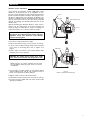
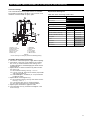
Magnetrol level controls are available with a range of different switch mechanisms—each designed for specific service con-
ditions. A brief description of the individual switch mechanisms and their applications are given below.
Figure 3
Series B, C, D, O, Q and U
Figure 4
Series S = Grp IV switch mech
D
ESCRIPTION
Dry contact switches B, C, D, O, Q, S and U
• Series B switches are general purpose with a maximum
liquid temperature rating of +120 °C (+250 °F), see
Figure 3.
• Series C switches are general purpose with a maximum
liquid temperature rating of +230 °C (+450 °F), see
Figure 3.
• Series D switches are designed for DC current applica-
tions with a maximum liquid temperature rating of
+120 °C (+250 °F), see Figure 3.
• Series O switches are general purpose with a maximum
liquid temperature rating of +150 °C (+300 °F), used only
in model C10 and C15 units, see Figure 3.
• Series Q switches are general purpose with a maximum
liquid temperature rating of +120 °C (+250 °F), used only
in model C10 and C15 units, see Figure 3.
• Series S switches are general purpose with a maximum
liquid temperature rating of +290 °C (+550 °F), or
designed for DC current applications with a maximum
liquid temperature of +120 °C (+250 °F), used only in
model B40 units, see Figure 4. (= Grp IV switch mech)
• Series U switches have gold alloy contacts and are suit-
able for applications with a maximum liquid temperature
of +120 °C (+250 °F).
Dry contact hermetically sealed switches W and X
Hermetically sealed switches are for use in special appli-
cations where hermetically sealed contacts are required.
• Series W switches are suitable for applications with a
maximum liquid temperature of +230 °C (+450 °F).
• Series X switches have gold-plated contacts and are
suitable for applications with a maximum liquid temper-
ature of +230 °C (+450 °F).
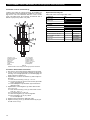
Figure 5
Series W & X
Figure 6
Series 8 & F
Figure 8
Series 9
Dry contact high temperature switches F, R, 8 and 9
• Series 8 and F switches are hermetically sealed and
designed for high temperature applications up to
+400 °C (+750 °F), see Figure 6.
• Series R switches are designed for the highest tempera-
ture applications up to +540 °C (+1000 °F) , see Figure 7.
• Series 9 switches are hermetically sealed and designed
for the highest temperature applications up to +540 °C
(+ 1000 °F), see Figure 8.
Figure 7
Series R

4
MOUNTING
CAUTION: Before attempting to remove a switch mechanism, be certain to pull disconnect switch or otherwise
assure that electrical circuit through control is de-energized.
Replacing the complete switch mechanisms
Replacing the switches only
1.
Remove the switch housing cover (see page 15 and up).
2. Disconnect wiring from supply side of terminal block
o
n switch mechanism. Note and record lead wire
terminal locations.
3. Loosen screw in split mounting clamp until mechanism
slides freely on enclosing tube, refer to Figure 9.
4. Remove small round head screw securing lower switch
mechanism to baffle plate, refer to Figure 10.
5. Slide switch mechanism off of enclosing tube. If mech-
anism is to be reused, ensure that it is placed on a
clean surface, free of metallic particles that may be
attracted to the switch magnet.
6. Loosen mounting screw so that switch frame will fit
over e-tube. Install switch mechanism by sliding it over
the enclosing tube. Slide mechanism down until the
bottom of the frame and terminal block are resting on
the baffle plate. The baffle plate should be resting on
the hub of the housing base.
7. Install and tighten baffle plate screw so that the switch
mechanism may not be separated from the baffle plate.
Tighten the mechanism mounting screw so that the
mechanism is firmly clamped to the enclosing tube.
8. Swing magnet assembly in and out by hand, checking
carefully for any signs of binding.
9. Reattached supply-side wiring to the terminal block.
10.
Reinstall the switch housing cover (see page 15 and up).
11. Reconnect power supply and test switch action under
operating conditions.
1.Disconnect control from power supply.
2.
Remove the switch housing cover (see page 15 and up).
3.Disconnect switch leads from terminal block. Note and
record terminal connections of switch to be replaced.
4.Remove two mounting screws holding existing switch,
refer to Figure 11.
5.Remove existing switch and install replacement switch
in the same position, tightening mounting screws
securely.
NOTE: For proper operation of the replacement
switch, it must actuate in the middle portion of the
pivoted magnet’s swing.
6.Check switch action and adjust as follows:
a. Slowly rotate the pivoted magnet by hand, back and
forth through its angle of swing, listening closely for
the actuating click of the switch in each direction.
b.Check to see if there is equal overtravel of magnet in
its swing after the switch click in either direction.
c. If switch actuation is not correct, change adjustment
of actuating screw using a
1
⁄16" hexagon key wrench,
refer to Figure 11.
Figure 9
Mounting screw
F
igure 10
Baffle plate screw
Figure 11
Baffle plate screw
Adjusting screw
Mounting screw
NOTE: If a single switch is being replaced on a
DPDT mechanism, lever of second switch must be
depressed and held to allow for the audible adjust-
ment of new switch, as described above.
d.With new switch in adjustment, release lever of sec-
ond switch and perform fine-tuning of both switches
to provide simultaneous actuation (clicks).
7.
Reinstall the switch housing cover (see page 15 and up).
8.Reconnect power supply and test switch action by vary-
ing liquid level in the vessel or by “gently blowing down”
float chamber.

5
CAUTION: Before attempting to remove a switch
mechanism, be certain to pull disconnect switch or
o
therwise assure that electrical circuit through
control is de-energized.
CAUTION: Be certain power supply wires retain
some slack at new position. Do not pull wires taut.
MOUNTING
Vibration service adjustment
Figure 12
Rotation of switch mechanism in vibration
Vessel
I
ncorrect
C
orrect
Baffle plate
Baffle plate
Swing of magnet
Direction of vibration
Direction of vibration
Frame mounting screw
Level controls are frequently used in applications where
v
ibration is encountered, such as on scrubbers or com-
pressors. Switch mechanisms may require repositioning to
prevent unwanted magnet movement. This position is usu-
ally best at right angles to the direction of vibration. The
direction of vibration may be determined by the arrange-
ment of connections to the vessel or the vessels mounting
method. Accordingly, the vibration will tend to be in one
direction only.
Upon determining the vibration direction, switch mecha-
nism(s) may be rotated from an incorrect position (as
shown in Figure 12, illustration is shown as looking at a
control from above), to a correct position as follows:
1.Disconnect control from power supply.
2.
Remove the switch housing cover (see page 15 and up).
3.Loosen screw in split mounting clamp until mechanism
turns freely on enclosing tube, refer to Figure 9 on
page 4.
4.Rotate entire mechanism and bottom baffle plate
together to the correct position.
NOTE: Amount of rotation required will vary with
each installation and may not be as much as shown
in illustration.
5.Check action of switch magnet at new position. When
magnet vibrates from side to side, instead of front to
back, correct position has been attained.
6.Tighten clamp screw on switch mechanism.
7.
Reinstall the switch housing cover (see page 15 and up).
8.Reconnect power supply and test switch action under
operating conditions.

6
WIRING
The units are shipped with the cable entry of the switch housing placed 90° opposite the tank connections to simplify installa-
tion in most cases. If the location of the cable entry on the level switch is appropriate to the installation, proceed to Step 4 to
begin wiring the unit. If another configuration is desired, the switch housing can be easily rotated by first following Steps 1, 2,
and 3.
1.Loosen set screw(s) at base of switch housing. Refer to Figure 13.
2.Switch housing may be rotated 360° to allow correct positioning of cable entry.
3.Tighten set screw(s) at base of switch housing.
4.Unscrew and remove switch housing cover. The threads have been lubricated to facilitate removal.
Caution: All units are shipped from the factory with the enclosing tube tightened and the switch housing set
screw locked to the enclosing tube. Failure to loosen the set screw prior to repositioning the supply and output
connections may cause the enclosing tube to loosen, resulting in possible leakage of the process liquid or vapor.
Caution: DO NOT attempt to unscrew cover of ATEX explosion proof housings before loosening locking screw in
cover (Figure 13 - ATEX cast aluminium) or base (Figure 14 - ATEX cast iron) of housing. ALWAYS retighten lock-
i
ng screw after replacing cover.
Caution: For units with explosion proof housing, do not power the unit until the cable gland is sealed and the
enclosure cover is screwed down securely.
NOTE: For supply connections use wire with a minimum rating of 75 °C, as required by process conditions. Use a min-
imum of 14 AWG wire for power and ground field wires. On high temperature applications (above 120 °C [250 °F] at
mounting flange or bushing), high temperature wire should be used between control and first junction box located in a
cooler area.
5.The switch terminals are located next to the cable entry to facilitate wiring. Bring supply wires through cable entry. Route extra
wire around enclosing tube under the baffle plate, and connect them to the proper terminals. Refer to the wiring diagram.
6.Dress wiring to ensure no interference or contact with the switch actuation arm, or replacement of switch housing cover.
NOTE: Observe all applicable electrical codes and proper wiring procedures.
Prevent moisture seepage into the enclosure by installing approved cable glands.
7.Replace housing cover and retighten locking screw in case of ATEX explosion proof housing.
8.Test switch action by varying liquid level in the tank or vessel.
NOTE: If switch mechanism fails to function properly, check vertical alignment of control housing.
9.Check cover to base fit to be certain gasketed joint is tight. A positive seal is necessary to prevent infiltration of moisture laden
air or corrosive gasses into switch housing.
Screw
S
et screw
Locking screw
Cover locking screw
(ATEX explosion
p
roof only)
Screw
Figure 13
Cast aluminium switch housing
Figure 14
ATEX cast iron switch housing

7
WIRING
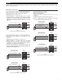
SPDT terminal connections
Circuits shown are for direct-acting level switches and are reversed in side mounting float-in-tank models, which
utilize a reversing float pivot.
Single float with one switch or single stage displacer
1.Rising level closes contacts 5 & 6, see Figure 15.
2
.Falling level closes contacts 4 & 5.
3.Wiring Diagram is reversed (high level actuation
becomes low level actuation, etc.) when this switch
mechanism is used on side mounted float switches
e
mploying a reversing pivot (Models B40, T52, T62, T63,
T64, etc.).
Single float with three switches
or three stage displacer
1
.Rising level closes contacts 5 & 6 and 2 & 3, see
Figure 17.
2.Falling level closes contacts 4 & 5 and 1 & 2.
3.Unit is shipped with switches positioned for proper
function. Do not change switch spacing.
4
5
6
Figure 15
S
ingle float with one switch or single stage displacer
C
lose on low level (NC)
Close on high level (NO)
C
ommon (C)
Line
L
oad
Load
Internal
c
ircuit
Figure 16
Single float with two switches or dual stage displacer
Figure 17
Single float with three switches or three stage displacer
Close on low level (NC)
Close on high level (NO)
Common (C)
Line
Load
Load
Internal
circuit
Close on low level (NC)
Upper stage operates
upper switch mechanism
Lower stage operates
lower switch mechanism
Close on high level (NO)
Common (C)
Line
Load
Load
Internal
circuit
Assem.
A
C
lose on low level (NC)
M
iddle stage operates
middle switch mechanism
C
lose on high level (NO)
Common (C)
Line
Load
L
oad
I
nternal
circuit
Assem.
A
Close on low level (NC)
Upper stage operates
u
pper switch mechanism
C
lose on high level (NO)
Common (C)
Line
L
oad
L
oad
I
nternal
circuit
Assem.
B
Assem.
B
Close on low level (NC)
Close on high level (NO)
Common (C)
Line
Load
Load
Internal
circuit
L
ower stage operates
lower switch mechanism
Assem.
B
Single float with two switches or dual stage displacer
1.Rising level closes contacts 5 & 6 and 2 & 3, see
Figure 16.
2.Falling level closes contacts 4 & 5 and 1 & 2.
3.Wiring diagram is reversed (high level actuation
becomes low level actuation, etc.) when this switch
mechanism is used on side mounted float switches
employing a reversing pivot. (Model T67).
4.On units with tandem floats, the top float operates the
bottom mechanism while the bottom float actuates the
top mechanism (Model T21).
1
2
3
4
5
6
4
5
6
4
5
6
1
2
3

8
WIRING
DPDT terminal connections
Single float with one switch or single stage displacer
1
.Rising level closes contacts 5 & 6 and 2 & 3, see
Figure 18.
2.Falling level closes contacts 4 & 5 and 1 & 2.
3.Double pole action is obtained by simultaneous opera-
tion of the right and left side single pole double throw
switches.
4.Wiring diagram is reversed (close on high becomes
close on low, etc.) when this switch mechanism is used
on side mounted float switches employing a reversing
pivot. (Models B40, T52, T62, T63, T64 etc.)
Three Stage Displacer
1.Rising level closes contacts 5 & 6 and 2 & 3, see
Figure 20.
2.Falling level closes contacts 4 & 5 and 1 & 2.
3
.Double pole action is obtained by simultaneous opera-
tion of the right and left side single pole switches.
F
igure 18
Single float with one switch or single stage displacer
Figure 19
Single float with two switches or dual stage displacer
Figure 20
Three stage displacer
Internal circuit
(
right switch)
I
nternal circuit
(left switch)
Close on low level (NC)
Close on high level (NO)
Common (C)
C
lose on low level (NC)
C
lose on high level (NO)
Common (C)
Load
Load
Load
I
nternal circuit
(right switch)
I
nternal circuit
(left switch)
Close on low level (NC)
Close on high level (NO)
C
ommon (C)
Close on low level (NC)
Close on high level (NO)
Common (C)
Load
L
oad
L
oad
Load
Internal circuit
(right switch)
Internal circuit
(left switch)
C
lose on low level (NC)
C
lose on high level (NO)
Common (C)
C
lose on low level (NC)
Close on high level (NO)
Common (C)
L
oad
Load
L
oad
Load
I
nternal circuit
(right switch)
I
nternal circuit
(left switch)
Close on low level (NC)
Close on high level (NO)
Common (C)
Close on low level (NC)
Close on high level (NO)
Common (C)
Load
Load
Load
Load
Middle stage operates
middle switch mechanism
Upper stage operates
u
pper switch mechanism
Upper stage operates
upper switch mechanism
Lower stage operates
l
ower switch mechanism
Lower stage operates
lower switch mechanism
1
2
3
4
5
6
1
2
3
4
5
6
1
2
3
4
5
6
1
2
3
4
5
6
Load
Internal circuit
(right switch)
Internal circuit
(left switch)
Close on low level (NC)
Close on high level (NO)
Common (C)
Close on low level (NC)
Close on high level (NO)
Common (C)
Load
Load
Load
Load
Internal circuit
(right switch)
Internal circuit
(left switch)
Close on low level (NC)
Close on high level (NO)
Common (C)
Close on low level (NC)
Close on high level (NO)
Common (C)
Load
Load
Load
Load
1
2
3
4
5
6
1
2
3
4
5
6
Single float with two switches or dual stage displacer
1.Rising level closes contacts 5 & 6 and 2 & 3, see
Figure 19.
2.Falling level closes contacts 4 & 5 and 1 & 2.
3.Double pole action is obtained by simultaneous opera-
tion of the right and left side single pole switches.
4.Wiring diagram is reversed (close on high becomes
close on low, etc.) when this switch mechanism is used
on side mounted float switches employing a reversing
pivot. (Model T67).
5.On units with tandem floats, the top float operates the
bottom mechanism while the bottom float actuates the
top mechanism. (Model T21).

9
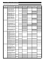
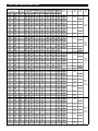
SWITCHES
Switch ratings
SWITCH
SERIES
SWITCH TYPE
Process
¿
Temperature range
°C (°F)
LOAD
RATING
Volts AC Volts DC
120 240 480 24 120 240
B Micro
-40 to +120
(-40 to +250)
Non-Inductive Amp 15.00 15.00 15.00 6.00 0.50 0.25
Inductive Amp 15.00 15.00 15.00 5.00 0.05 0.03
C Micro
-40 to +230
(-40 to +450)
Non-Inductive Amp 15.00 15.00 15.00 6.00 1.00 0.50
Inductive Amp 15.00 15.00 15.00 5.00 0.05 0.03
D Micro
-40 to +120
(-40 to +250)
Non-Inductive Amp 10.00 – – 10.00 10.00
1.50 min
3.00 max
Inductive Amp 3.80 – – – 2.20 –
F Hermetic
-45 to +400
(-50 to +750)
Resistive Amp 2.50 – –
4.00
¡
0.30 –
Inductive Amp 2.50 – –
2.00
¡
0.10 –
O Micro
-40 to +150
(-40 to +300)
Non-Inductive Amp 15.00 15.00 15.00 6.00 1.00 0.50
Inductive Amp 15.00 15.00 15.00 5.00 0.05 0.03
Q Micro
-40 to +120
(-40 to +250)
Non-Inductive Amp 15.00 15.00 15.00 6.00 0.50 0.25
Inductive Amp 15.00 15.00 15.00 5.00 0.05 0.03
R Micro
-40 to +540
(-40 to +1000)
Non-Inductive Amp 1.00 1.00 – 1.00 0.40 –
Inductive Amp 1.00 1.00 – 1.00 0.40 –
S
Micro
VAC-applications
-40 to +290
(-40 to +550)
Non-Inductive Amp 15.00 15.00 15.00 – 1.00 0.50
Inductive Amp 15.00 15.00 15.00 – 0.50 –
S
Micro
VDC-applications
-40 to +120
(-40 to +250)
Non-Inductive Amp 10.00 – – 10.00 10.00
1.50 min
3.00 max
Inductive Amp 3.80 – – – 2.20 –
U
Micro
(Gold contacts)
-40 to +120
(-40 to +250)
Non-Inductive Amp 1.00 – –
1.00
¡
– –
Inductive Amp 1.00 – –
0.50
¡
– –
W
Hermetic
(Silver contacts)
-45 to +230
(-50 to +450)
Non-Inductive Amp 1.00 1.00 –
3.00
➂
0.50 –
Inductive Amp – 0.40 –
1.50
➂
– –
X
Hermetic
(Gold contacts)
-45 to +230
(-50 to +450)
Non-Inductive Amp 0.50 0.50 – 0.50 0.50 –
Inductive Amp – – – – – –
8 Hermetic
-45 to +400
(-50 to +750)
Non-Inductive Amp 1.00 – – 3.00 – –
Inductive Amp 1.00 – – 1.00 – –
9 Hermetic
-45 to +540
(-50 to +1000)
Non-Inductive Amp 1.00 – –
1.00
¡
– –
Inductive Amp 1.00 – –
1.00
¡
– –
¿ Max. Process Temperature based on +40 °C (+100 °F) ambient temperature.
¡ 28 V DC.
➂ 30 V DC.
PREVENTIVE MAINTENANCE
Inspect switch mechanisms, terminals and connections
Inspect switch mechanisms, terminals and connections regularly. Proof test interval to be determined by application require-
ments (required reliability, operating conditions, site requirements, etc).
1. Dry contact switches should be inspected for excessive wear on actuating lever or misalignment of adjustment screw at
point of contact between screw and lever. Such wear can cause false switch actuating levels
2. DO NOT operate your control with defective or maladjusted switch mechanisms.
3. Level controls may sometimes be exposed to excessive heat or moisture. Under such conditions, insulation on electrical
wiring may become brittle, eventually breaking or peeling away. The resulting “bare” wires can cause short circuits.
NOTE: Check wiring carefully and replace at the first sign of brittle insulation.
4
.
V
ibration may sometimes cause terminal screws to loosen. Check all terminal connections to be certain that screws are tight.
NOTE: Spare switches should be kept on hand at all times.

10
REPLACEMENT SWITCH MECHANISMS
Magnet strength
Yellow dot magnet replacement mechanisms
Switch mechanisms are provided with different strength magnets as determined by the characteristics of the level switch. A red
or yellow dot is visible on each magnet. When ordering replacement switch mechanisms, be certain to determine the color dot
on the magnet. For these types of switches, the last 3 digits of the model number identify the switch and magnet used on the
control. The correct magnet dot color may be chosen by finding those 3 digits of your model number in the chart. Any model
numbers preceded with an “X” are specially modified controls. Contact the factory for replacement part numbers.
Switch
Series
8th, 9th & 10th Digit
Switch
Contacts
Set points Bottom Mech Middle Mech Top Mech Switch Only
B
BAB, BAQ, BA9, BC9, BH9,
BKB, BKQ, BK5, BK9, BU5,
B2B, B2Q
SPDT
1
089-7401-104
--
089-7101-020
BBB, BBN, BD9, BLB, BL5,
BL9, BV5, B4B, B4N
2-
089-7401-103
BCB, BE9, BMB, BM9,
B6B, B65, B75
3
089-7401-103 089-7401-104
BB9, BDB, BDQ, BD5, BF9,
BJ9, BNB, BNQ, BN9,
BW5, B8B, B8Q
DPDT
1
089-7401-122
--
089-7101-020
BEB, BEN, BG9, BOB,
BO5, BP9, BY5, B1B, B1N
2-089-7401-122
C
CAB, CAQ, CAS, CAT,
CA9, CC9, CH9, CKB,
CKQ, CK5, CK9, CU5,
C2B, C2Q, C2S, C2T
SPDT
1
089-7401-110
--
089-7101-022
CBB, CBT, CD9, CLB, CL5,
CL9, CV5, C4B, C4T
2-
089-7401-109
CCB, CE9, CMB, CM9,
C6B, C65, C75
3
089-7401-109 089-7401-110
CB9, CDB, CDQ, CDS,
CDT, CD5, CF9, CJ9, CNB,
CNQ, CN9, CW5, C8B,
C8Q, C8S, C8T
DPDT
1
089-7401-125
--
089-7101-022
CEB, CET, CG9, COB,
CO5, CP9, CY5, C1B, C1T
2-
089-7401-125
D
DAB, DAQ, DA9, DC9,
DH9, DKB, DKQ, DK5,
DK9, DU5, D2B, D2Q
SPDT
1
089-7401-106
--
089-7101-024
DBB, DD9, DLB, DL5, DL9,
DV5, D4B
2-
089-7401-105
DCB, DE9, DMB, DM9,
D6B, D65, D75
3 089-7401-105 089-7401-106
DB9, DDB, DDQ, DD5,
DF9, DJ9, DNB, DNQ,
DN9, DW5, D8B, D8Q
DPDT
1
089-7401-123
--
089-7101-024
DEB, DG9, DOB, DO5,
DP9, DY5, D1B
2-
089-7401-123
F
FAB, FAQ, FA9, FCB, FC9,
FH9, FKB, FKQ, FK5, FK9,
FU5, F2Q
SPDT
1
089-7401-095
--
089-7101-041
FBB, FD9, FFB, FLB, FL5,
FL9, FV5
2-089-7401-096
FB9, FDB, FDQ, FD5, FF9,
FGB, FJ9, FNB, FNQ, FN9,
FW5, F8Q
DPDT
1
089-7401-098
--
089-7101-041
FEB, FG9, FHB, FOB, FO5,
FP9, FY5
2-089-7401-098
FMB, FM9, FSB, FWB, FY9
SPDT
Group IV
1 089-7401-218 --
089-7101-041
FHM, FM5, FN5 1 089-7401-214 --
FE9, FTB, FVB, FYB, FZ9
DPDT
Group IV
1 089-7401-220 --
FJM, FP5, FZ5 1 089-7401-216 --
1X
74
2 3 8 9 105 6
Digit in partn°:
Partn°:
Serial n°:
X = product with a specific customer requirement
See nameplate, always provide complete partn° and
serial n° when ordering spares.
EXPEDITE SHIP PLAN (ESP)
Several parts are available for quick shipment, within max. 1 week after factory receipt of purchase order, through the
E
xpedite Ship Plan (ESP).
Parts covered by ESP service are conveniently grey coded in the selection tables.

11
REPLACEMENT SWITCH MECHANISMS
Yellow dot magnet replacement mechanisms
Switch
Series
8th, 9th & 10th Digit
Switch
Contacts
Set points Bottom Mech Middle Mech Top Mech Switch Only
O
OCB, OMB, O6B SPDT 3
089-7401-110 089-7401-109 089-7401-110
089-7101-022
OEB, OKB, O1B DPDT 3
089-7401-125 089-7401-125 089-7401-125
Q
QCB, QMB, Q6B SPDT 3
089-7401-104 089-7401-103 089-7401-104
089-7101-020
QEB, QKB, Q1B DPDT 3
089-7401-122 089-7401-122 089-7401-122
R
RA9, RC9, RH9, RKB,
RKQ, RK5, RK9, RU5, R1B,
R1M, R1Q, R1Y, R2B, R2Q
SPDT
1
089-7401-179
--
089-7101-045
RD9, RLB, RL5, RL9, RV5,
R3B, R3M, R4B
2-089-7401-178
RB9, RDB, RDM, RDQ,
RDY, RF5, RF9, RGB, RJ9,
RNB, RNQ, RN5, RN9, R8Q
DPDT
1
089-7401-181
--
089-7101-045
REB, REM, RG5, RG9,
RHB, ROB, RO5, RP9
2-089-7401-181
RW9, RYB, RY9, R5B, R6B
SPDT
Group IV
1 089-7401-203 --
089-7101-045
RW5, RY5, R5M 1 089-7401-180 --
RFB, RJB, RM9, RSB, RS9
DPDT
Group IV
1 089-7401-204 --
089-7101-045
RJM, RM5, RS5 1 089-7401-182 --
S
(AC Volt)
SAB, SA9, SH9, SKB, S2B
SPDT
Group IV
1
089-7401-161 --
089-7101-022
SAM 089-7401-126 --
SB9, SDB, SJ9, SNB, S8B
DPDT
Group IV
1
089-7401-163 --
SDM 089-7401-128 --
S
(DC Volt)
SBB, SC9, SK9, SLB, S2R
SPDT
Group IV
1
089-7401-162 --
089-7101-024
SBM 089-7401-129 --
SEB, SF9, SN9, SOB, S8R
DPDT
Group IV
1
089-7401-164 --
SEM 089-7401-127 --
U
UAB, UAQ, UAS, UAT, UA9,
UC9, UH9, UKB, UKQ,
UK5, UK9, UU5, U2B, U2Q,
U2S, U2T
SPDT
1
189-9109-901
--
189-9105-901
UBB, UBT, UD9, ULB, UL5,
UL9, UV5, U4B, U4T
2-
189-9107-901
UCB, UE9, UMB, UM9,
U6B, U65, U75
3
189-9107-901 189-9109-901
UB9, UDB, UDQ, UDS,
UDT, UD5, UF9, UJ9, UNB,
UNQ, UN9, UW5, U8B,
U8Q, U8S, U8T
DPDT
1
189-9111-901
--
189-9105-901
UEB, UET, UG9, UOB,
UO5, UP9, UY5, U1B, U1T
2-
189-9111-901

12
REPLACEMENT SWITCH MECHANISMS
Yellow dot magnet replacement mechanisms
Switch
Series
8th, 9th & 10th Digit
Switch
Contacts
Set points Bottom Mech Middle Mech Top Mech Switch Only
W
WAB, WAQ, WAS, WAT,
WA9, WC9, WH9, WKB,
WKQ, WK5, WK9, WU5,
W2B, W2Q, W2S, W2T
SPDT
1
089-7410-004
--
089-7411-001
WBB, WBT, WD9, WLB,
WL5, WL9, WV5, W4B,
W4T
2-089-7410-003
WCB, WE9, WMB, WM9,
W6B, W65, W75
3 089-7410-003 089-7410-004
WB9, WDB, WDQ, WDS,
WDT, WD5, WF9, WJ9,
WNB, WNQ, WN9, WW5,
W8B, W8Q, W8S, W8T
DPDT
1
089-7410-005
--
089-7411-001
WEB, WET, WG9, WOB,
WO5, WP9, WY5, W1B,
W1T
2-089-7410-005
X
XAB, XAQ, XAS, XAT, XA9,
XC9, XH9, XKB, XKQ, XK5,
XK9, XU5, X2B, X2Q, X2S,
X2T
SPDT
1
089-7412-004
--
089-7413-001
XBB, XBT, XD9, XLB, XL5,
XL9, XV5, X4B, X4T
2-089-7412-003
XCB, XE9, XMB, XM9, X6B,
X65, X75
3
089-7412-003 089-7412-004
XB9, XDB, XDQ, XDS, XDT,
XD5, XF9, XJ9, XNB, XNQ,
XN9, XW5, X8B, X8Q, X8S,
X8T
DPDT
1
089-7412-005
--
089-7413-001
XEB, XET, XG9, XOB, XO5,
XP9, XY5, X1B, X1T
2-
089-7412-005
8
8AB, 8AQ, 8A9, 8C9, 8H9,
8KB, 8KQ, 8K5, 8K9, 8U5,
82B, 82Q
SPDT
1
089-7401-185
--
037-4632-001
8BB, 8D9, 8LB, 8L5, 8L9,
8V5, 84B
2-089-7401-186
8CB, 8E9, 8MB, 86B, 865,
875, 889
3 089-7401-186 089-7401-185
8B9, 8DB, 8DQ, 8D5, 8F9,
8J9, 8NB, 8NQ, 8N9, 8W5,
88B, 88Q
DPDT
1
089-7401-192
--
037-4632-001
8EB, 8G9, 8OB, 8O5, 8P9,
8Y5, 81B
2-089-7401-192
8FB, 8SB, 8M9, 8Y9, 83B
SPDT
Group IV
1 089-7401-206 --
037-4632-001
8HM, 8M5, 8N5 1 089-7401-188 --
8GB, 8S9, 8TB, 8Z9, 87B
DPDT
Group IV
1 089-7401-208 --
037-4632-001
8JM, 8P5, 8Z5 1 089-7401-190 --
9
9AB, 9AM, 9AQ, 9AY, 9A9,
9C9, 9H9, 9KB, 9KQ, 9K5,
9K9, 9U5, 92B, 92Q
SPDT
1
089-7401-198
--
037-4633-001
9BB, 9BM, 9D9, 9LB, 9L5,
9L9, 9V5, 94B
2-089-7401-199
9CB, 9CM, 9E9, 9MB, 96B,
965, 975, 989
3 089-7401-199 089-7401-198
9B9, 9DB, 9DM, 9DQ, 9DY,
9D5, 9F9, 9J9, 9NB, 9NQ,
9N9, 9W5, 98B, 98Q
DPDT
1
089-7401-200
--
037-4633-001
9EB, 9EM, 9G9, 9OB, 9O5,
9P9, 9Y5, 91B
2-089-7401-200
9FB, 9M9, 9SB, 9Y9, 93B
SPDT
Group IV
1 089-7401-211 --
037-4633-001
9HM, 9M5, 9N5 1 089-7401-201 --
9GB, 9S9, 9TB, 9Z9, 97B
DPDT
Group IV
1 089-7401-212 --
037-4633-001
9JM, 9P5, 9Z5 1 089-7401-202 --

13
REPLACEMENT SWITCH MECHANISMS
Red dot magnet replacement mechanisms
Switch
Series
8th, 9th & 10th Digit
Switch
Contacts
Set points Bottom Mech Middle Mech Top Mech Switch Only
B
BAA, BAC, BAP, BCC,
BHC, BKA, BKC, BKP, BK7,
BU7, B2A, B2P
SPDT
1
089-7401-102
--
089-7101-020
BBA, BBP, BDC, BLA, BLC,
BL7, BV7, B4A, B4P
2-
089-7401-101
BCA, BEC, BMA, BMC,
B6A, B67, B77
3
089-7401-101 089-7401-102
BBC, BDA, BDP, BD7, BFC,
BJC, BNA, BNC, BNP,
BW7, B8A, B8P
DPDT
1
089-7401-121
--
089-7101-020
BEA, BEP, BGC, BOA,
BO7, BPC, BY7, B1A, B1P
2-
089-7401-121
C
CAA, CAC, CAL, CAP, CAX,
CCC, CHC, CKA, CKC,
CKP, CK7, CU7, C2A, C2L,
C2P, C2X
SPDT
1
089-7401-108
--
089-7101-022
CBA, CBX, CDC, CLA,
CLC, CL7, CV7, C4A, C4X
2-
089-7401-107
CCA, CEC, CMA, CMC,
C6A, C67, C77
3
089-7401-107 089-7401-108
CBC, CDA, CDL, CDP,
CDX, CD7, CFC, CJC,
CNA, CNC, CNP, CW7,
C8A, C8L, C8P, C8X
DPDT
1
089-7401-124
--
089-7101-022
CEA, CEX, CGC, COA,
CO7, CPC, CY7, C1A, C1X
2-
089-7401-124
F
FAA, FAC, FAP, FCA, FCC,
FHC, FKA, FKC, FKP, FK7,
FU7, F2P
SPDT
1
089-7401-093
--
089-7101-041
FBA, FDC, FFA, FLA, FLC,
FL7, FV7
2-089-7401-094
FBC, FDA, FDP, FD7, FFC,
FGA, FJC, FNA, FNC, FNP,
FW7, F8P
DPDT
1
089-7401-097
--
089-7101-041
FEA, FGC, FHA, FOA, FO7,
FPC, FY7
2-089-7401-097
FMA, FMC, FSA, FWA,
FYC
SPDT
GROUP
IV
1 089-7401-217 --
089-7101-041
FHD, FM7, FN7 1 089-7401-213 --
FEC, FTA, FVA, FYA, FZC
DPDT
GROUP
IV
1 089-7401-219 --
FJD, FP7, FZ7 1 089-7401-215 --
U
UAA, UAC, UAL, UAP, UAX,
UCC, UHC, UKA, UKC,
UKP, UK7, UU7, U2A, U2L,
U2P, U2X
SPDT
1
189-9108-901
--
189-9105-901
UBA, UBX, UDC, ULA,
ULC, UL7, UV7, U4A, U4X
2-
189-9106-901
UCA, UEC, UMA, UMC,
U6A, U67, U77
3
189-9106-901 189-9108-901
UBC, UDA, UDL, UDP,
UDX, UD7, UFC, UJC,
UNA, UNC, UNP, UW7,
U8A, U8L, U8P, U8X
DPDT
1
189-9110-901
--
189-9105-901
UEA, UEX, UGC, UOA,
UO7, UPC, UY7, U1A, U1X
2-
189-9110-901

14
REPLACEMENT SWITCH MECHANISMS
Red dot magnet replacement mechanisms
Switch
Series
8th, 9th & 10th Digit
Switch
Contacts
Set points Bottom Mech Middle Mech Top Mech Switch Only
W
WAA, WAC, WAL, WAP,
WAX, WCC, WHC, WKA,
WKC, WKP, WK7, WU7,
W2A, W2L, W2P, W2X
SPDT
1
089-7410-002
--
089-7411-001
WBA, WBX, WDC, WLA,
WLC, WL7, WV7, W4A,
W4X
2-
089-7410-001
WCA, WEC, WMA, WMC,
W6A, W67, W77
3
089-7410-001 089-7410-002
X
XAA, XAC, XAL, XAP, XAX,
XCC, XHC, XKA, XKC, XKP,
XK7, XU7, X2A, X2L, X2P,
X2X
SPDT
1
089-7412-002
--
089-7413-001
XBA, XBX, XDC, XLA, XLC,
XL7, XV7, X4A, X4X
2-089-7412-001
XCA, XEC, XMA, XMC,
X6A, X67, X77
3
089-7412-001 089-7412-002
8
8AA, 8AC, 8AP, 8CC, 8HC,
8KA, 8KC, 8KP, 8K7, 8U7,
82A, 82P
SPDT
1
089-7401-183
--
037-4632-001
8BA, 8DC, 8LA, 8LC, 8L7,
8V7, 84A
2-089-7401-184
8CA, 8EC, 8MA, 86A, 867,
877, 88C
3 089-7401-184 089-7401-183
8BC, 8DA, 8DP, 8D7, 8FC,
8JC, 8NA, 8NC, 8NP, 8W7,
88A, 88P
DPDT
1
089-7401-191
--
037-4632-001
8EA, 8GC, 8OA, 8O7, 8PC,
8Y7, 81A
2-089-7401-191
8FA, 8SA, 8MC, 8YC, 83A
SPDT
Group IV
1 089-7401-205 --
037-4632-001
8HD, 8M7, 8N7 1 089-7401-187 --
8GA, 8SC, 8TA, 8ZC, 87A
DPDT
Group IV
1 089-7401-207 --
037-4632-001
8JD, 8P7, 8Z7 1 089-7401-189 --
9
9AA, 9AC, 9AD, 9AP, 9AR,
9CC, 9HC, 9KA, 9KC, 9KP,
9K7, 9U7, 92A, 92P
SPDT
1
089-7401-193
--
037-4633-001
9BA, 9BD, 9DC, 9LA, 9LC,
9L7, 9V7, 94A
2-089-7401-194
9CA, 9CD, 9EC, 9MA, 96A,
967, 977, 98C
3 089-7401-194 089-7401-193
9BC, 9DA, 9DD, 9DP, 9DR,
9D7, 9FC, 9JC, 9NA, 9NC,
9NP, 9W7, 98A, 98P
DPDT
1
089-7401-195
--
037-4633-001
9EA, 9ED, 9GC, 9OA, 9O7,
9PC, 9Y7, 91A
2-089-7401-195
9FA, 9MC, 9SA, 9YC, 93A
SPDT
Group IV
1 089-7401-209 --
037-4633-001
9HD, 9M7, 9N7 1 089-7401-196 --
9GA, 9SC, 9TA, 9ZC, 97A
DPDT
Group IV
1 089-7401-210 --
037-4633-001
9JD, 9P7, 9Z7 1 089-7401-197 --

15
REPLACEMENT SWITCH HOUSINGS (standard, NOT for use with group IV switch mechanism)
Switch housing replacement assemblies
When ordering replacement parts for an existing Magnetrol instrument, please specify:
1.Model and serial numbers of control.
2
.Description and part number of replacement kit.
The proper replacement switch housing kit and parts can be determined by the last three characters of the model number.
Die cast aluminum TYPE 4X housing replacements are
available for general purpose or weatherproof installations.
Explosion proof NEMA 7/9 and ATEX housing replace-
ments are available for hazardous atmosphere locations.
Die cast aluminum housings are finished with a baked-on
p
olyester powder coat paint.
Figure 21
Standard cast aluminium housing (short and tall)
1
2
3
1
0
4
5
7
6
8
9
1. Housing cover
2. Baffle plate
3. Housing base
4. Stopping plug
5. Base lock screw
6. Base lock screw
7. Base O-ring
8. Cover lock screw
9. Cover O-ring
10. Caution tag
Assemble / Disassemble instructions
1. Disconnect control from power supply before opening.
2. In case of ATEX Ex d approved housing, first unlock
cover lock screw (8) before unscrewing the cover (1)
counterclockwise. Lift housing cover straight upwards
to avoid damaging the inside switch mechanism.
3. Replacement of housing base (3) and/or base O-ring
(7).
3.1 First remove housing cover (1) - see 1-2.
3.2 Remove entire switch mechanism (see page 4).
3.3 Loosen base lock screws (5) & (6).
3.4 Slide housing base (3) of enclosing tube.
3.5 O-ring (7) can be accessed/replaced.
4. Replace part and mount in opposite order.
5. Close housing cover (1) clockwise and tighten cover
lock screw (8) in case of ATEX Ex d approved housing.
Cast aluminum housings (short and tall)
R
eplacement housing kits
Table with switch & housing model codes:
Column header Data
Switch contacts "SPDT" or "DPDT"
H
ousing height
"
Short" or "Tall"
H
ousing type
A
TEX Ex d, flameproof
Switch & housing code e.g. BH9, BA9, BHC, BAC, ...
Description
Kit contains part(s) Replacement part
Cover kit for short housing 1, 8, 9, 10 089-6582-035
Cover kit for tall housing 1, 8, 9, 10 089-6582-037
Base kit for M20 x 1,5 cable entry 3, 4, 5, 6, 7, 9 089-6582-040
Base kit for 1" NPT-F cable entry 3, 4, 5, 6, 7, 9 089-6582-041
Cover 'O'-ring 9 012-2201-253
Base 'O'-ring 7 012-2201-116
Baffle plate 2 005-6657-001
Housing type Weatherproof (IP 66)
S
witch & housing code
e
.g. B2Q, BAQ, B2P, BAP, ...
Description
Kit contains part(s) Replacement part
Cover kit for short housing 1, 9, 10 089-6582-034
C
over kit for tall housing 1, 9, 10 089-6582-031
Base kit for M20 x 1,5 cable entry 3, 4, 5, 6, 7, 9 089-6582-039
B
ase kit for 1" NPT-F cable entry 3, 4, 5, 6, 7, 9 089-6582-030
Cover 'O'-ring 9 012-2201-253
Base 'O'-ring 7 012-2201-116
Baffle plate 2 005-6657-001
Housing type ATEX Ex i, intrinsically safe
Switch & housing code e.g. C2S, CAS, C2L, CAL, ...
Description
Kit contains part(s) Replacement part
Cover kit for short housing 1, 9, 10 089-6582-036
Cover kit for tall housing 1, 9, 10 089-6582-038
Base kit for M20 x 1,5 cable entry 3, 4, 5, 6, 7, 9 089-6582-042
Base kit for 1" NPT-F cable entry 3, 4, 5, 6, 7, 9 089-6582-043
Cover 'O'-ring 9 012-2201-253
Base 'O'-ring 7 012-2201-116
Baffle plate 2 005-6657-001
Housing type FM NEMA 7/9, explosion proof
Switch & housing code e.g. BKQ, BKP, BKB, BKA, ...
Description
Kit contains part(s) Replacement part
Cover kit for short housing 1, 9, 10 089-6582-034
Cover kit for tall housing 1, 9, 10 089-6582-031
Base kit for 1" NPT-F cable entry 3, 4, 5, 6, 7, 9 089-6582-030
Cover 'O'-ring 9 012-2201-253
Base 'O'-ring 7 012-2201-116
Baffle plate 2 005-6657-001

16
REPLACEMENT SWITCH HOUSINGS (standard, NOT for use with group IV switch mechanism)
8
12
11
Figure 22
Extra tall cast aluminium housing
1
2
3
1
0
4
5
7
6
9
1. Housing cover
2. Baffle plate
3. Housing base
4. Stopping plug
5. Base lock screw
6. Base lock screw
7. Base O-ring
8.
Cover lock screw (not applicable)
9. Cover O-ring
10. Caution tag
11. Cover extension O-ring
12. Housing extension
Assemble / Disassemble instructions
1. Disconnect control from power supply before opening.
2. Unscrew the cover (1) and housing extension (12)
counterclockwise and lift housing cover straight
upwards to avoid damaging the inside switch mecha-
nism.
3. Replacement of housing base (3) and/or base O-ring
(7).
3.1 First remove housing cover (1) and housing exten-
sion (12) - see 1-2.
3.2 Remove entire switch mechanism (see page 4).
3.3 Loosen base lock screws (5) & (6).
3.4 Slide housing base (3) of enclosing tube.
3.5 O-ring (7) can be accessed/replaced.
4. Replace part and mount in opposite order.
5. Close housing cover (1) and housing extension (12)
clockwise.
Die cast aluminum TYPE 4X housing replacements are
available for general purpose or weatherproof installations.
Explosion proof NEMA 7/9 housing replacements are
available for hazardous atmosphere locations. Die cast
aluminum housings are finished with a baked-on polyester
powder coat paint.
Extra tall cast aluminum housings
R
eplacement housing kits
Table with switch & housing model codes:
Column header Data
Switch contacts "SPDT" or "DPDT"
H
ousing height
"
X-Tall"
H
ousing type
W
eatherproof (IP 66)
S
witch & housing code
e
.g. O6B, OCB, O1B, OEB, ...
D
escription
K
it contains part(s)
R
eplacement part
C
over kit for tall housing 1, 9, 10 089-6582-031
Housing extension 12 004-9175-002
B
ase kit for M20 x 1,5 cable entry 3, 4, 5, 6, 7, 11 089-6582-039
Base kit for 1" NPT-F cable entry 3, 4, 5, 6, 7, 11 089-6582-030
C
over extension 'O'-ring 11
0
12-2201-253
Cover 'O'-ring 9 012-2201-253
B
ase 'O'-ring 7
0
12-2201-116
Baffle plate 2 005-6657-001
H
ousing type
F
M NEMA 7/9, explosion proof
S
witch & housing code
O
MB, OKB, QMB, QKB
D
escription
K
it contains part(s)
R
eplacement part
Cover kit for tall housing 1, 9, 10 089-6582-031
Housing extension 12 004-9175-002
Base kit for 1" NPT-F cable entry 3, 4, 5, 6, 7, 11 089-6582-030
Cover extension 'O'-ring 11 012-2201-253
Cover 'O'-ring 9 012-2201-253
Base 'O'-ring 7 012-2201-116
Baffle plate 2 005-6657-001

17
REPLACEMENT SWITCH HOUSINGS (standard, NOT for use with group IV switch mechanism)
Carbon steel TYPE 4X switch housings are available for
general purpose and weatherproof installations. The hous-
ing base is cast from aluminum while the cover is made
from cold rolled steel. The housings are finished with a
baked-on polyester powder coat paint.
Cast iron ATEX Exd housing replacements are available for
hazardous atmosphere locations. The cast iron cover and
base are finished with an epoxy paint.
Figure 23
Standard cast iron housing
1. Housing cover
2. Baffle plate
3. Housing base
4. Cover lock screw
5. Base lock nut
6. Caution tag
7. Nameplate
8. Cover gasket
Assemble / Disassemble instructions
1. Disconnect control from power supply before opening.
2. First unlock cover lock screw (4) before unscrewing
the cover (1) counterclockwise.
3. Lift housing cover straight upwards to avoid damaging
the inside switch mechanism.
4. Replacement of housing base (3).
4.1 First remove housing cover (1) - see 1-3.
4.2 Remove entire switch mechanism (see page 4).
4.3 Loosen base lock nut (5) counterclockwise.
4.4 Unscrew housing base (3) counterclockwise.
5. Replace and mount in opposite order.
6. Close housing cover (1) clockwise and tighten cover
lock screw (4).
1
4
3
6
7
5
8
2
F
igure 24
Standard aluminium /carbon steel housing (short and tall)
1
. Housing cover
2
. Baffle plate
3. Housing base
4. Acorn nut
5. Washer
6
. Seal washer
7
. Base O-ring
8. Base lock screw
9. Cover O-ring
10. Nameplate
Assemble / Disassemble instructions
1. Disconnect control from power supply before opening.
2. Loosen acorn nut (4) or cover screw (model F10 &
F50) and remove washers (5) & (6). Lift housing cover
straight upwards to avoid damaging the inside switch
mechanism.
3. Replacement of housing base (3) and/or base O-ring
(7).
3.1 First remove housing cover (1) - see 1-2.
3.2 Remove entire switch mechanism (see page 4).
3.3 Loosen base lock screw (8).
3.4 Slide housing base (3) of enclosing tube.
3.5 O-ring (7) can be accessed/replaced.
4. Replace part and mount in opposite order.
5. Replace housing cover (1), reinstall washers (6) & (5)
and fix with acorn nut (4) or cover screw (model F10 &
F50).
1
2
10
9
4
5
7
3
8
6
Cast iron housings Aluminium / Carbon steel housings
Replacement housing kits
Table with switch & housing model codes:
Replacement housing kits
Table with switch & housing model codes:
Column header Data
Switch contacts "SPDT" or "DPDT"
Housing height "Tall"
Housing type ATEX Ex d, flameproof
Switch & housing code e.g. BK5, BU5, BK7, BU7, ...
Description
Kit contains part(s) Replacement part
Cover kit 1, 6, 8 189-9122-001
Base kit for M20 x 1,5 cable entry 3, 4, 5, 7 189-9126-002
Base kit for 3/4" NPT-F cable entry 3, 4, 5, 7 189-9126-001
Cover gasket 8 012-1301-005
Baffle plate assembly 2 036-5303-003
Column header Data
Switch contacts "SPDT" or "DPDT"
Housing height "Short" or "Tall"
Housing type Weatherproof (IP 65)
Switch & housing code e.g. R1Y, R1M, R3M, RDY, ...
Description
Kit contains part(s) Replacement part
Cover kit for short housing 1, 4, 5, 6, 7, 9 189-6509-001
Cover kit for tall housing 1, 4, 5, 6, 7, 9 189-6510-001
Base kit for 3/4" NPT-F cable entry 3, 7, 8, 9, 10 089-6505-003
Washer + 'O'-ring kit 4, 5, 6, 7, 9 189-6508-001
Cover 'O'-ring 9 012-1318-001
Base 'O'-ring 7 012-2201-116
Baffle plate assembly 2 036-5303-003

18
REPLACEMENT SWITCH HOUSINGS (for use with group IV switch mechanism)
Die cast aluminum TYPE 4X housing replacements are
available for general purpose or weatherproof installa-
tions. Explosion proof NEMA 7/9 and ATEX housing
replacements are available for hazardous atmosphere
locations. Die cast aluminum housings are finished with a
baked-on polyester powder coat paint.
Figure 25
Cast aluminium housing for use with group IV switch mechanism (high temp.)
1
2
1
4
3
10
4
5
7
6
8
9
1. Housing cover
2. Switch mechanism
3. Housing base
4. Stopping plug
5. Base lock screw
6. Base lock screw
7. Base O-ring
8. Cover lock screw
9. Cover O-ring
10. Caution tag
11. Screw
12. Lock washer
13. Top insulator
14. Base insulator
Assemble / Disassemble instructions
1. Disconnect control from power supply before opening.
2. In case of ATEX Ex d approved housing, first unlock
cover lock screw (8) before unscrewing the cover (1)
counterclockwise. Lift housing cover straight upwards
to avoid damaging the inside switch mechanism (2).
3. Replacement of switch mechanism (2) and/or insula-
tors (13) & (14).
3.1 First remove housing cover (1) - see 1-2.
3.2 Loosen screw (11), remove lock washer (12) and
lift switch mechanism (2).
3.3 Reinstall/Replace insulators (13) & (14) and mount
in opposite order.
4. Replacement of housing base (3) or base O-ring (7).
4.1 First remove housing cover (1) and switch mecha-
nism (2) – see 1-3.
4.2 Loosen base lock screws (5) & (6).
4.3 Slide housing base (3) of enclosing tube.
4.4 O-ring (7) can be accessed/replaced.
5. Replace part and mount in opposite order.
6. Close housing cover (1) clockwise and tighten cover
lock screw (8) in case of ATEX Ex d approved housing.
11
12
13
Cast aluminum housings
Replacement housing kits
Table with switch & housing model codes:
C
olumn header
D
ata
S
witch contacts
"
SPDT Grp IV" or "DPDT Grp IV"
Housing height "Tall"
Housing type Weatherproof (IP 66)
Switch & housing code e.g. FWB, FMB, FWA, FMA, ...
Description
Kit contains part(s) Replacement part
Cover kit 1, 9, 10 089-6582-031
B
ase kit for M20 x 1,5 cable entry 3, 4, 5, 6, 7, 9 089-6582-039
Base kit for 1" NPT-F cable entry 3, 4, 5, 6, 7, 9 089-6582-030
C
over 'O'-ring 9
0
12-2201-253
Base 'O'-ring 7 012-2201-116
S
crew 11
0
10-1402-015
Lock washer 12 010-3101-003
R
ing gasket 13
0
12-1301-013
Base insulator 14 012-9307-001
H
ousing type
A
TEX Ex d, flameproof
Switch & housing code e.g. FY9, FM9, FYC, FMC, ...
Description
Kit contains part(s) Replacement part
Cover kit 1, 8, 9, 10 089-6582-037
Base kit for M20 x 1,5 cable entry 3, 4, 5, 6, 7, 9 089-6582-040
Base kit for 1" NPT-F cable entry 3, 4, 5, 6, 7, 9 089-6582-041
Cover 'O'-ring 9 012-2201-253
Base 'O'-ring 7 012-2201-116
Screw 11 010-1402-015
Lock washer 12 010-3101-003
Ring gasket 13 012-1301-013
Base insulator 14 012-9307-001
Housing type FM NEMA 7/9, explosion proof
Switch & housing code e.g. FSB, FSA, FTB, FTA, ...
Description
Kit contains part(s) Replacement part
Cover kit 1, 9, 10 089-6582-031
Base kit for 1" NPT-F cable entry 3, 4, 5, 6, 7, 9 089-6582-030
Cover 'O'-ring 9 012-2201-253
Base 'O'-ring 7 012-2201-116
Screw 11 010-1402-015
Lock washer 12 010-3101-003
Ring gasket 13 012-1301-013
Base insulator 14 012-9307-001

19
REPLACEMENT SWITCH HOUSINGS (for use with group IV switch mechanism)
2
9
10
11
Cast iron ATEX Exd housing replacements are available
for hazardous atmosphere locations. The cast iron cover
and base are finished with an epoxy paint.
Figure 26
Cast iron housing for use with group IV switch mechanism (high temp.)
1. Housing cover
2. Switch mechanism
3. Housing base
4. Cover lock screw
5. Base lock nut
6. Caution tag
7. Nameplate
8. Cover gasket
9. Screw
10. Lock washer
11. Top insulator
12. Base insulator
Assemble / Disassemble instructions
1. Disconnect control from power supply before opening.
2. First unlock cover lock screw (4) before unscrewing
the cover (1) counterclockwise. Lift housing cover
straight upwards to avoid damaging the inside switch
mechanism (2).
3. Replacement of switch mechanism (2) and/or insula-
tors (11) & (12).
3.1 First remove housing cover (1) - see 1-2.
3.2 Loosen screw (9), remove lock washer (10) and lift
switch mechanism (2).
3.3 Reinstall/Replace insulators (11 & 12) and mount
in opposite order.
4. Replacement of housing base (3).
4.1 First remove housing cover (1) and switch mecha-
nism (2) – see 1-3.
4.2 Loosen base lock nut (5) counterclockwise.
4.3 Unscrew housing base (3) counterclockwise.
5. Replace part and mount in opposite order.
6. Close housing cover (1) clockwise and tighten cover
lock screw (4).
1
4
1
2
3
6
7
5
8
Replacement housing kits
Table with switch & housing model codes:
Cast iron housings
C
olumn header
D
ata
Switch contacts "SPDT Grp IV" or "DPDT Grp IV"
H
ousing height
"
Tall"
H
ousing type
A
TEX Ex d, flameproof
S
witch & housing code
e
.g. FN5, FM5, FN7, FM7, ...
D
escription
K
it contains part(s)
R
eplacement part
C
over kit 1, 6, 8 189-9122-001
Base kit for M20 x 1,5 cable entry 3, 4, 5, 7 189-9126-002
B
ase kit for 3/4" NPT-F cable entry 3, 4, 5, 7 189-9126-001
Cover gasket 8 012-1301-005
S
crew 9
0
10-1402-015
Lock washer 10 010-3101-003
R
ing gasket 11
0
12-1301-013
Base insulator 12 012-9307-001

20
REPLACEMENT SWITCH HOUSINGS (for use with group IV switch mechanism)
Aluminium / Carbon steel housings
Figure 27
Aluminium /carbon steel housing for use with group IV switch mechanism
1. Housing cover
2. Switch mechanism
3. Housing base
4. Acorn nut
5. Washer
6. Seal washer
7. Stud
8. Hex nut
9. Lock washer
10. Top insulator
11. Base insulator
12. Base insulator
13. Base lock screw
14. Cover O-ring
15. Nameplate
Assemble / Disassemble instructions
1. Disconnect control from power supply before opening.
2. Loosen acorn nut (4) and remove washers (5) & (6). Lift
housing cover straight upwards to avoid damaging the
inside switch mechanism (2).
3. Replacement of switch mechanism (2) and/or top insu-
lator (10).
3.1 First remove housing cover (1) - see 1-2.
3.2 Loosen hex nut (8), remove lock washer (9) and lift
switch mechanism (2).
3.3 Reinstall/Replace top insulator (10) and mount in
opposite order.
4. Replacement of housing base (3) and/or base insula-
tors (11) & (12).
4.1 First remove housing cover (1) and switch mecha-
nism (2) – see 1-3.
4.2 Loosen base lock screw (13).
4.3 Slide housing base (3) of enclosing tube.
4.4 Base insulators (11) & (12) can be
accessed/replaced.
5. Replace part and mount in opposite order.
6. Replace housing cover (1), reinstall washers (6) & (5) &
fix with acorn nut (4).
1
2
8
11
1
2
10
4
5
3
1
3
15
7
9
6
14
Carbon steel TYPE 4X switch housings are available for
general purpose and weatherproof installations. The hous-
ing base is cast from aluminum while the cover is made
from cold rolled steel. The housings are finished with a
baked-on polyester powder coat paint.
Replacement housing kits
Table with switch & housing model codes:
Column header Data
Switch contacts "SPDT Grp IV" or "DPDT Grp IV"
H
ousing height
"
Tall"
Housing type Weatherproof (IP 65)
Switch & housing code e.g. FHM, FHD, FJM, FJD, ...
Description
Kit contains part(s) Replacement part
Cover kit 1, 4, 5, 6, 14 189-6510-001
B
ase kit for 3/4" NPT-F cable entry 3 002-6101-736
Washer, insulation + 'O'-ring kit
4, 5, 6, 10, 11, 12, 14
189-6508-002
B
ase lock srew 13
0
10-1202-007
Cover 'O'-ring 14 012-1318-001
Page is loading ...
Page is loading ...
Page is loading ...
Page is loading ...
-
 1
1
-
 2
2
-
 3
3
-
 4
4
-
 5
5
-
 6
6
-
 7
7
-
 8
8
-
 9
9
-
 10
10
-
 11
11
-
 12
12
-
 13
13
-
 14
14
-
 15
15
-
 16
16
-
 17
17
-
 18
18
-
 19
19
-
 20
20
-
 21
21
-
 22
22
-
 23
23
-
 24
24


Magnetrol Electric Switch Series B, C, D, F, O, Q, R, S, U, W, X, 8 and 9 User manual
- Type
- User manual
- This manual is also suitable for
Ask a question and I''ll find the answer in the document
Finding information in a document is now easier with AI
Related papers
-
Magnetrol High Temperature Switch User manual
-
-
-
-
-
-
-
Magnetrol Model B40 Operating instructions
-
-
Other documents
-
Posiflex KS-7410 / KS-7412 User manual
-
Trane Performance Air Handlers Catalogue
-
McQuay WDC User manual
-
Kramer Electronics C-FM9/FM9-15 Datasheet
-
 Magnetek DSD 412 Technical Manual
-
ABB LMS100 Series Operating Instructions Manual
-
 Magnetek DSD® 412 DC Elevator Drive Owner's manual
-
Moxa UC-7100 Series Quick setup guide
-
 Magnetek 4012-FGV+S3 User manual
-
Hitachi SJ700B SERIES User manual


