Page is loading ...

PROGRAMMING GUIDE
XR200 COMMAND PROCESSOR™ PANEL and
XR2400F ADDRESSABLE FIRE ALARM CONTROL PANEL

MODEL XR200
COMMAND PROCESSOR
PROGRAMMING GUIDE
FCC NOTICE
This equipment generates and uses radio frequency energy and, if not installed and used properly in strict accordance with
the manufacturer's instructions, may cause interference with radio and television reception. It has been type tested and
found to comply with the limits for a Class B computing device in accordance with the specification in Subpart J of Part 15
of FCC Rules, which are designed to provide reasonable protection against such interference in a residential installation. If
this equipment does cause interference to radio or television reception, which can be determined by turning the equipment
off and on, the installer is encouraged to try to correct the interference by one or more of the following measures:
Reorient the receiving antenna
Relocate the computer with respect to the receiver
Move the computer away from the receiver
Plug the computer into a different outlet so that computer and receiver are on different branch circuits
If necessary, the installer should consult the dealer or an experienced radio/television technician for additional suggestions.
The installer may find the following booklet, prepared by the Federal Communications Commission, helpful:
"How to identify and Resolve Radio-TV Interference Problems."
This booklet is available from the U.S. Government Printing Office, Washington D.C. 20402
Stock No. 004-000-00345-4
Copyright © 1995 - 2002 Digital Monitoring Products, Inc.
Information furnished by DMP is believed to be accurate and reliable.
This information is subject to change without notice.

iii
Digital Monitoring Products XR200/XR2400F Programming Guide
TABLE OF CONTENTS
PageSection
Introduction
Revisions to This Document ........................................................ viii
1.1 Before you begin ............................................................ 1
1.2 Getting Started .............................................................. 1
1.3 Programmer Operation..................................................... 2
1.4 Programmer Lockout Codes............................................... 2
1.5 Reset Timeout ................................................................ 3
1.6 Special Keys ................................................................... 3
1.7 Entering Alpha Characters ................................................ 3
1.8 Entering Non-Alpha Characters .......................................... 4
1.9 Keypad Prompts Display Current Programming...................... 4
Initialization
2.1 Initialization .................................................................. 5
2.2 Clear All Memory ............................................................ 5
2.3 Clear All Codes ............................................................... 5
2.4 Clear All Schedules.......................................................... 5
2.5 Clear Display Events Memory ............................................ 5
2.6 Clear Zone Information .................................................... 5
2.7 Clear Area Information .................................................... 5
2.8 Clear Output Information ................................................. 5
2.9 Clear Communication and Remote Options .......................... 5
2.10 Set to Factory Defaults .................................................... 5
Communication
3.1 Communication .............................................................. 6
3.2 Communication Type ....................................................... 6
3.2.1 Retry Time ..................................................................... 6
3.2.2 Host Backup ................................................................... 7
3.2.3 Modem Setup ................................................................. 7
3.2.4 UL AA ............................................................................ 8
3.3 2ND Phone Line .............................................................. 9
3.3.1 Test Frequency ..............................................................10
3.4 Account Number ............................................................10
3.5 Transmit Delay .............................................................. 10
3.6 DTMF ...........................................................................10
3.7 Events Manager ............................................................. 10
3.8 Defer Test Time .............................................................11
3.9 Test Frequency ..............................................................11
3.10 Test Time .....................................................................11
3.11 Receiver One Programming ..............................................12
3.12 Alarm Reports ...............................................................12
3.13 Supervisory/Trouble Reports ............................................ 12
3.14 Opening/Closing and User Reports ....................................12
3.15 Test Report ...................................................................12
3.16 Backup Reporting ...........................................................12
3.17 First Telephone Number ..................................................12
3.18 Second Telephone Number ...............................................12
3.19 Receiver One Programming ..............................................13
3.20 Pager Type .................................................................... 13
3.21 Alarm Reports ...............................................................13
3.22 Supervisory/Trouble Reports ............................................ 13
3.23 Opening/Closing and User Reports ....................................13
3.24 Test Report ...................................................................13
3.25 Backup Reporting ...........................................................13
3.26 First Telephone Number ..................................................13
3.27 Second Telephone Number ...............................................13
3.28 Pager Identification Number ............................................ 13

XR200/XR2400F Programming Guide Digital Monitoring Products
iv
TABLE OF CONTENTS
PageSection
Device Setup
4.1 Device Setup .................................................................14
4.2 Maximum Partitions ........................................................14
4.3 Device Type .................................................................. 14
4.4 Partition Number ...........................................................14
Remote Options
5.1 Remote Options .............................................................15
5.2 Remote Key................................................................... 15
5.3 Manufacturer Authorization ............................................. 15
5.4 Armed Rings .................................................................. 15
5.5 Disarmed Rings ..............................................................15
5.6 Alarm Receiver Authorization ...........................................15
5.7 Service Receiver Authorization .........................................16
5.8 Remote Phone Number ....................................................16
5.9 Remote Disarm ..............................................................16
System Reports
6.1 System Reports ..............................................................17
6.2 Abort Report .................................................................17
6.3 Restoral Reports ............................................................17
6.4 Bypass Reports .............................................................. 17
6.5 Schedule Change Reports................................................. 17
6.6 Code Change Reports ...................................................... 17
6.7 Access Keypads.............................................................. 17
6.8 Ambush ........................................................................17
System Options
7.1 System Options.............................................................. 18
7.2 Closing Wait.................................................................. 18
7.3 Entry Delay 1 ................................................................18
7.4 Cross Zone Time ............................................................18
7.5 Zone Retard Delay .......................................................... 18
7.6 Power Fail Delay ............................................................18
7.7 Swinger Bypass Trips.......................................................18
7.8 Reset Swinger Bypass ...................................................... 18
7.9 Video/Alarm Verification.................................................19
7.10 Time Zone Changes ........................................................ 19
7.11 AC Cycles .....................................................................19

v
Digital Monitoring Products XR200/XR2400F Programming Guide
TABLE OF CONTENTS
PageSection
Output Options
8.1 Output Options .............................................................. 20
8.2 Bell Cutoff Time ............................................................ 20
8.3 Automatic Bell Test ........................................................20
8.4 Bell Action .................................................................... 20
8.4.1 Fire Bell Action ............................................................. 20
8.4.2 Burglary Bell Action........................................................20
8.4.3 Supervisory Bell Action ................................................... 20
8.4.4 Panic Bell Action ............................................................ 20
8.4.5 Emergency Bell Action ....................................................20
8.4.6 Auxiliary 1 Bell Action ....................................................20
8.4.7 Auxiliary 2 Bell Action ....................................................20
8.5 Output Action................................................................ 20
8.5.1 Cutoff Output................................................................ 20
8.5.2 Output Cutoff Time ........................................................ 20
8.5.3 Communication Fail Output .............................................21
8.5.4 Fire Alarm Output .......................................................... 21
8.5.5 Fire Trouble Output ........................................................21
8.5.6 Ambush Output .............................................................. 21
8.5.7 Entry Output .................................................................21
8.5.8 Exit Output ...................................................................21
8.5.9 Ready Output ................................................................21
8.5.10 Phone Trouble Output ..................................................... 21
8.5.11 Late To Close Output ......................................................21
8.5.12 Device Fail Output .........................................................21
8.5.13 Sensor Reset Output ....................................................... 21
Menu Display
9.1 Menu Display ................................................................. 22
9.2 Armed Status ................................................................ 22
9.3 Time ............................................................................ 22
9.4 Arm/Disarm .................................................................. 22
Status List
10.1 Status List .................................................................... 23
10.2 Display Keypads ............................................................. 23
10.3 System Monitor Troubles .................................................23
10.4 Fire Zones ....................................................................23
10.5 Burglary Zones ..............................................................24
10.6 Supervisory Zones ..........................................................24
10.7 Panic Zones ..................................................................24
10.8 Emergency Zones ........................................................... 24
10.9 Auxiliary 1 Zones ........................................................... 24
10.10 Auxiliary 2 Zones ........................................................... 24
Printer Reports
11.1 Printer Reports ..............................................................25
11.2 Arm and Disarm Reports .................................................. 25
11.3 Zone Reports .................................................................25
11.4 User Command Reports ...................................................25
11.5 Door Access Reports .......................................................25
11.6 Supervisory Reports ........................................................ 25

XR200/XR2400F Programming Guide Digital Monitoring Products
vi
TABLE OF CONTENTS
PageSection
Host Log Reports
12.1 Host Log Reports............................................................ 26
12.2 Modem Setup ................................................................ 26
12.3 Arm and Disarm Reports .................................................. 26
12.4 Zone Reports .................................................................26
12.5 User Command Reports ...................................................26
12.6 Door Access Reports .......................................................26
12.7 Supervisory Reports ........................................................ 26
Area Information
13.1 Area Information ........................................................... 27
13.2 Partition Number ...........................................................27
13.3 Arming Mode ................................................................. 27
13.4 Exit Delay.....................................................................27
13.5 Burglary Bell Output .......................................................27
13.6 Opening/Closing Reports ................................................. 28
13.7 Closing Check ................................................................ 28
13.8 Closing Code .................................................................28
13.9 Any Bypass.................................................................... 28
13.10 Area Schedules .............................................................. 28
13.11 Primary/Secondary Schedules........................................... 28
13.12 Area Number .................................................................28
13.13 Area Name ....................................................................29
13.14 Account Number ............................................................29
13.15 Automatic Arming ..........................................................29
13.16 Bad Zones ..................................................................... 29
13.17 Automatic Disarming ......................................................29
13.18 Armed Output Number ....................................................30
13.19 Common Area ................................................................ 30
Zone Information
14.1 Zone Information ........................................................... 31
14.2 Zone Number ................................................................ 31
14.3 Zone Name ................................................................... 31
14.4 Zone Type .....................................................................31
14.5 Fire Bell Output.............................................................32
14.6 Partition Number ...........................................................32
14.6.1 Area Number .................................................................32
14.6.2 Area Assignment ............................................................32
14.6.3 Arming Zone Area Assignment .......................................... 32
14.6.4 Style............................................................................ 33
14.7 Next Zone.....................................................................33
14.7.1 Wireless .......................................................................34
14.7.2 Check-in Time ...............................................................34
14.7.3 Internal Contact ............................................................ 34
14.7.4 End-of-Line ................................................................... 34
14.7.5 Normally Open ..............................................................34
14.8 Alarm Action .................................................................34
14.9 Disarmed Open ..............................................................34
14.9.1 Report to Transmit .........................................................35
14.9.2 Output Number ..............................................................35
14.9.3 Output Action................................................................ 35
14.10 Swinger Bypass .............................................................. 36
14.11 Prewarn Addresses ......................................................... 36
14.12 Entry Delay ...................................................................36

vii
Digital Monitoring Products XR200/XR2400F Programming Guide
TABLE OF CONTENTS
PageSection
14.13 Zone Retard ..................................................................36
14.14 Presignal Addresses ........................................................36
14.15 Fast Response ...............................................................36
14.16 Cross Zone .................................................................... 37
14.17 Priority ........................................................................37
14.17.1 Program Transmitter ....................................................... 37
14.17.2 Connect Transmitter .......................................................37
14.17.3 Connect Command Transmitter .........................................37
Stop
15.1 Stop ............................................................................ 38
Set Lockout Code
16.1 Set Lockout Code ...........................................................38
Appendix
17.1 Diagnostics function ....................................................... 39
17.2 Using the 984 Command Function .....................................40
17.3 Using the Walk Test ........................................................ 41
Walk Test......................................................................41
Zone Types....................................................................41
Bell Action ....................................................................41
Trip Counter.................................................................. 41
Failed Zones Display ....................................................... 42
Local Printer for Walk Test .............................................. 42
17.4 690 Series Keypads Speaker Operation ............................... 42
17.5 Pager Direct Specifications .............................................. 42
17.6 Cross Zoning .................................................................43
17.7 Events Manager ............................................................. 43
17.8Modem Setup Information................................................43
17.9 Host Backup Examples ....................................................44
17.10 462N Network Interface Card Examples .............................45
17.11 Zone Type Descriptions ................................................... 46
17.12 Zone Type Specifications .................................................47
17.13 Common Keypad Messages ............................................... 48

XR200/XR2400F Programming Guide Digital Monitoring Products
viii
TABLE OF CONTENTS
PageSection
REVISIONS
Revisions to This Document
This section explains the changes that were made to this document during this revision. This section lists the date
and the change that was made, the section number and section heading, and a quick summary of the change.
Date Section Number and Heading Quick Explanation of Changes
5/02 2.2 Clear All Memory Programming Prompt added to initialize all programming.
5/02 3.6 DTMF Programming Default changed to YES
5/02 3.9 Test Frequency Programming Default changed to 1
5/02 7.4 Cross Zone Time Programming Default changed to 4.
5/02 17.10 462N Examples Table revised for clarity.
3/02 3.2.4 UL AA Check-in Time and Fail Time defaults changed to 1 (one).
1/02 3 Communication DNET programming type removed.
1/02 12 Host Log Reports Section added for Host Log Reports feature.
Note: All subsequent section numbers adjusted.
1/02 17.9 462N Examples Section added to explain how to use the 462N card with Host Log
Reports, Host Communication, and Host Backup.
12/01 3.2.1 Retry Time Section added for new programming operation.
12/01 3.2.2 Host Backup Section added for new programming operation.
12/01 3.2.3 Modem Setup Section expanded for new programming operation.
12/01 3.2.4 UL AA Section added for new programming operation.
12/01 16 Appendix Entire section rearranged for clarity.
21/01 16.3 Using the Walk Test Clarification added regarding bells.
12/01 16.5 Pager Direct Specifications Information added about Pager Direct.
12/01 16.6 Cross Zoning Clarification added about method of reporting tripped cross zones.
12/01 16.8 Modem Setup Information Information added regarding modem setup strings.
12/02 16.9 Host Backup Examples Scenarios for Host Backup added for clarity.
12/01 16.12 Common Keypad Examples Section added to help troubleshoot some common keypad messages
that may appear on the keypad display.
12/01 Entire Document New Layout.

XR200/XR2400F Programming Guide Digital Monitoring Products
1
1 - INTRODUCTION
1.1 Before you begin
This guide provides programming information for the DMP XR200 Command Processor™ Panel and the XR2400F
Addressable Fire Alarm Control Panel. After this Introduction, the remaining sections describe the functions of each
programming menu item along with the available options. Before starting to program, we recommend you read
through the contents of this guide. The information contained here allows you to quickly learn the programming
options and operational capabilities of the panel.
In addition to this guide, you should also read and be familiar with the following XR200 documents:
• XR200 Installation Guide (LT-0197)
• XR200 Product Specification (LT-0198)
• XR200 Security Command
®
User's Guide (LT-0287)
If you are using the XR2400F Addressable Fire Alarm Control Panel, you should also read and be familiar with these
documents:
• XR2400F Installation Guide (LT-0554)
• XR2400F Product Specification (LT-0517)
• XR2400F User's Guide (LT-0560)
Internal Programmer
The panel contains all of its programming information in an on-board processor and does not require an external
programmer. You can perform all programming tasks through a DMP alphanumeric keypad set to address one.
Programming Information Sheet
Included with each panel are the Programming Information Sheets. These list the various programming prompts and
available options for programming the panel. Before starting to program, we recommend you completely fill out
each sheet with the programming options you intend to enter into the panel.
Having completed programming sheets available while entering data helps prevent errors and can shorten the time
you spend programming. Completed sheets also provide you with an accurate record of the panel's program you can
keep on file for future system service or expansion. The remainder of this Introduction provides instructions for
starting and ending a programming session using the alphanumeric keypad.
1.2 Getting Started
Ground Yourself Before Handling the Panel! Touch any grounded metal, such as the enclosure, before
touching the panel to discharge static.
Remove All Power From the Panel! Remove all AC and Battery power from the panel before installing
or connecting any modules, cards, or wires to the panel.
Before starting to program the panel, make sure the panel is properly grounded, and also ensure that the AC and
battery power is applied to the appropriate panel terminals. All wiring connections and grounding instructions are
detailed in the XR200 Installation Guide (LT-0197) and the XR2400F Installation Guide (LT-0554).

Digital Monitoring Products XR200/XR2400F Programming Guide
2
1 - INTRODUCTION
Accessing the Programmer
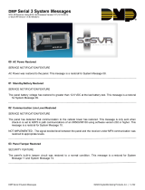
1. Install the reset jumper across the two J16 reset pins for two seconds. See Figure 1.
2. Remove the reset jumper and place it over just one pin for future use.
3. Enter the code 6653 (PROG) into an alphanumeric keypad set to address one. Press COMMAND.
4. The keypad displays PROGRAMMER.
You are now ready to start programming the panel. Pressing the COMMAND key scrolls you through the programming
functions listed in the programmer. Each of these functions are described in detail in sections 2 to 15.
Initializing the Panel
After installing the panel, use the Initialization function to set to defaults the panel's programming. Note: The
default user code is 99. This should be changed as soon as the system is operational.
1.3 Programmer Operation
There are 14 programming sections to choose from:
Menu Item Section Menu Item Section
Initialization 2 Menu Display 9
Communication 3 Status List 10
Device Setup 4 Printer Reports 11
Remote Options 5 Area Information 12
System Reports 6 Zone Information 13
System Options 7 Stop 14
Output Options 8 Set Lockout Code 15
To select a section for programming, press any one of the Select keys when the name of that section is displayed on
the keypad. The detailed instructions for each programming step are found in sections 2 to 15.
1.4 Programmer Lockout Codes
The panel allows you to enter the programming function without entering a lockout code using the steps 1 to 4 listed
in Getting Started. We recommend, however, that you install a Lockout Code that restricts programming to only
those persons your company authorizes. You can do this by using the SET LOCKOUT CODE feature in the
Programmer. Use this new Lockout Code to restrict any unauthorized programming of the panel.
After resetting the panel and entering the code 6653, the keypad displays PROGRAMMER. Press COMMAND to
advance through the programming sections until SET LOCKOUT CODE is displayed (after STOP). Press any top row
Select key. The keypad displays ENTER CODE: – . Enter a 3 to 5 digit Programmer Lockout Code and press
COMMAND. The keypad displays ENTER AGAIN followed by ENTER CODE: –. Enter the same 3 to 5 digit code a
second time and press COMMAND. The keypad displays CODE CHANGED.
Note: The panel will not accept a 5-digit Lockout Code higher than 65535. The new code number must now be
entered before the programmer function can be accessed.
The Lockout Code should be written down and kept in a secure place with access limited to only those persons
authorized by your company to program the panel.
J16
Command Processor Reset
AC
1
234
56
78
10 11 12
13
14
15
16
17
18
19
AC +B -B
BELL
GND SMK
GND
9
RED
YEL GRN BLK
20
21
22 23 24 25
26
27 28
L1 L2
GND
GND
GND
GND
L3
L4 L5 L6 L7 L8 L9- L9+ L10- L10+
Figure 1: J16 Reset Jumper

XR200/XR2400F Programming Guide Digital Monitoring Products
3
1 - INTRODUCTION
1.5 Reset Timeout
The panel has a feature that requires you to enter the Programmer within 30 minutes of resetting the panel. After
30 minutes, if you attempt to program by entering the 6653 (PROG) code, the keypad displays: RESET PANEL. You
must reset the panel and enter the program code within the next 30 minutes.
If you are already in the Programmer and do not press any keys on the programming keypad for 30 minutes, the
panel terminates programming. All data entered up to that time is saved in the panel's memory.
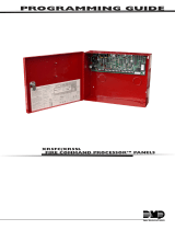
1.6 Special Keys
COMMAND Key
The COMMAND key allows you to go forward through the programming menu and through each step of a programming
section. As you go through the programming, the keypad display shows any current programming already stored in
the panel's memory. If the information is not to be changed, press the COMMAND key to advance to the next step.
The COMMAND key is also used to enter information into the panel's memory such as phone numbers or zone names.
Press the COMMAND key after you have entered the information and it is being displayed correctly on the keypad.
Back Arrow Key
Use the Back Arrow key to back up one step while programming.
The Back Arrow key is also used when an error is made while
entering information. Press the Back Arrow key once to erase the
last character entered.
Select Keys
The top row of keys are called the Select keys. Each time a Select
key is to be used, the keypad displays the function or options above
the key. Displaying choices above the individual Select keys allows
them to be used for many different applications. For example, you
can enter AM or PM when programming the automatic test time or
answer YES or NO for a system option.
During programming, the Select keys also allow you to change information currently in the panel's memory by
pressing the appropriate Select key under the display then entering the new information through the keypad.
When there are more than four response options available, pressing the COMMAND key brings up the next 1 to 4
options on the keypad display. Pressing the Back Arrow key allows you to review the previous four choices.
The Select keys are also used for selecting a section from the programming menu by pressing any one of the Select
keys when the name of the programming section you want is displayed.
1.7 Entering Alpha Characters
Some options during programming require you to enter alpha characters. To enter an alpha character, press the key
that has that letter written below it. The keypad displays the number digit of the key. Next, press the Select key
that corresponds to the location of the letter under the key. Pressing a different Select key changes the letter.
When another digit key is pressed, the last letter displayed is retained and the process is started over.
A BC D E F G H I J KL
V WX
M N O
P Q R
S T U
Y Z
COMMAND
90
1234
56
7
8
POWER
ABC PRINTING
FRI 2: 51 AM
ARMED
Back Arrow Key
Select Keys
Figure 2: Keypad Function keys
COMMAND Key
Figure 3: Keypad Display and Select keys
Left
Character
Special
Character
Center
Character
Right
Character
(
CBA

Digital Monitoring Products XR200/XR2400F Programming Guide
4
1 - INTRODUCTION
1.8 Entering Non-Alpha Characters
To enter a space in an alpha entry, press the 9 digit key
followed by the third Select key. The three characters on
the 9 digit key are Y, Z, and space. You can also enter the
following characters: – (dash), . (period), * (asterisk), and
# (pound sign) using the zero key and the four Select keys
from left to right. For example, to enter a – (dash), press
the zero key and then the left Select key. A dash now
appears in the keypad display.
1.9 Keypad Prompts Display Current Programming
Each programming prompt displayed at the keypad shows the currently selected option in the panel's memory. These
options are either shown as a number, a blank, or a NO or YES. To change a number or blank to a new number, press
any top row Select key. The current option is replaced with a dash. Press the number(s) on the keypad you want to
enter as the new number for that prompt.
It is not necessary to enter numbers with leading zeros. The panel automatically right justifies the number when you
press the COMMAND key.
To change a programming prompt that requires a NO or YES response, press the top row Select key under the
response not selected.
For example, if the current prompt is selected as YES and you want to change it to NO, press the third top row
Select key. The display changes to NO. Press the COMMAND key to go to the next prompt. See Figure 5.
BELL TST YES
Press a top row select key.
BELL TST NO
The keypad display changes to the newly
selected option. Press COMMAND.
NEXT
Figure 5: Changing the Current Programming Option
90
1234
5678
COMMAND
ABC ( DEF ) GHI ! JKL ?
MNO / PQR & STU $ VWX ,
YZ
(space)
'
- . * #
Figure 4: Special Characters

XR200/XR2400F Programming Guide Digital Monitoring Products
5
2.1 Initialization
This function allows you to clear selected parts of the panel's program back to the
factory defaults in preparation for system programming.
2.2 Clear All Memory
NO - Leaves existing programming intact.
YES - Clears all memory.
2.3 Clear All Codes
NO - Leaves existing codes intact.
YES - Clears the user code memory and assigns the user code number 99 to the
highest user position in each partition.
2.4 Clear All Schedules
NO - Leaves existing schedules intact.
YES - Clears all primary, secondary, permanent, temporary, and output schedules.
2.5 Clear Display Events Memory
NO - Leaves existing event memory intact.
YES - Clears the Security Command keypad display events memory.
2.6 Clear Zone Information
NO - Leaves existing zone information intact.
YES - Clears the zone information for all zones. All zones are marked * UNUSED *
and must be renamed before being able to display on any system keypad.
2.7 Clear Area Information
NO - Leaves existing area information intact.
YES - Clears the area information for all areas. All areas are marked * UNUSED *
and must be renamed before being able to display on any system keypad.
2.8 Clear Output Information
NO - Leaves existing output information intact.
YES - Clears all programmed Output names and any output cutoff assignment.
2.9 Clear Communication and Remote Options
NO - Leaves existing communication and remote options intact.
YES - Clears communication and remote options programming to factory defaults.
2.10 Set to Factory Defaults
NO - Leaves existing panel programming intact.
YES - Sets the remainder of the panel's programming back to the factory defaults.
CODES? NO YES
SURE? YES NO
SCHEDS? NO YES
For each initialization section, the
Programmer provides a NO or YES option.
Selecting NO advances you to the next
section prompt and does not initialize
that section of the program.
Selecting YES advances you to a
confirmation prompt.
If you select YES, the panel initializes that section of the
program and advances you to the next section prompt.
If you select NO, the panel advances you to the next section
prompt but does not initialize that section of the program.
EVENTS? NO YES
AREAS? NO YES
SURE? YES NO
INITIALIZATION
CODES? NO YES
SURE? YES NO
SCHDS? NO YES
SURE? YES NO
SURE? YES NO
ZONES? NO YES
SURE? YES NO
OUTPUTS? NO YES
SURE? YES NO
COM/RMT? NO YES
SURE? YES NO
DEFAULTS NO YES
SURE? YES NO
2 - INITIALIZATION
INIT ALL? NO YES
SURE? YES NO

Digital Monitoring Products XR200/XR2400F Programming Guide
6
3 - COMMUNICATION
3.1 Communication
This section of programming allows you to configure the communication options
for the panel. The information you program varies with the Communication Type
you select.
3.2 Communication Type
Specifies the communication method the panel uses to report system events to
DMP SCS-1 Receivers or non-DMP receivers. Press any Select key.
NONE - For local systems. Selecting this ends communication programming.
When COMM TYPE = NONE and there is an unrestored System Trouble, then the
keypad will sound daily at 10:00 AM.
DD - Digital Dialer communication to a DMP SCS-1 Receiver.
MPX - Multiplex communication to a DMP SCS-1 Receiver.
M2E - Modem IIe communication to non-DMP receivers. This format sends the
report codes of the Radionics Modem IIe communication format to the receiver(s)
programmed in Receiver 1 and 2 programming. Once the receiver has been
contacted, the panel waits approximately 45 seconds for the Modem IIe handshake
before hanging up and making another attempt.
Note: Do not use the M2E communication option if the system has over 255 zones
and/or over 254 users. When using Modem IIe to communicate between a
Radionics D6500 receiver and the XR200-485 panel, zone numbers 256 to 299 and
user numbers 255 to 999 CANNOT be received by the D6500. Zone numbers
greater than 255 will be reported as 255. User numbers greater than 254 will be
reported as 000.
CID - This option allows the panel to communicate to non-DMP receivers using the
Ademco Contact ID format. When selected, the panel sends all of its alarm,
trouble, and supervisory reports to the receiver(s) programmed in Receiver 1 and
2 Programming. The panel sends reports to the receiver using either CID or
standard DMP SDLC based on each receiver's ability to process the CID format.
The panel determines whether the receiver can process the CID format by the
acknowledgment tones the receiver transmits when first contacted. If the
receiver can process the CID format, only those event reports for which there are
CID definitions will be sent by the panel. This restriction prevents the panel from
dialing the receiver for a report it cannot send.
HST (Host) - Asynchronous communication using the 462N Network Interface Card.
The DMP Host/Output reporting format is transmitted over an asynchronous data
network to the SCS-1 Receiver. If you need to send a duplicate signal to the
central station and you have selected HST, use Receiver 2 programming to send
the duplicate signal.
Note: When HST is selected, 2ND LINE programming allows you to select D2 for
two line supervision when using a Model 893 or 893A Dual Phone Line Module.
There are extra options available if you selected HST for the communication type.
These options are explained in sections 3.2.1 through 3.2.4.
3.2.1 Retry Time
After selecting HST, the keypad displays RETRY TIME: -. Enter the number of
seconds (3 to 15 seconds) the panel should wait before retrying to send a message
to the receiver if an acknowledgment was not received. The panel will retry as
many times as possible for a period of one minute before sending a network
trouble message. For example, if RETRY TIME is set to 15, the panel will retry 4
times. The default RETRY TIME is 5 seconds.
RETRY TIME: -
NONE DD MPX M2E
COMM TYPE: DD
COMMUNICATION
C I D HST

XR200/XR2400F Programming Guide Digital Monitoring Products
7
3 - COMMUNICATION
3.2.2 Host Backup
After displaying the RETRY TIME prompt, the keypad displays HST BCKUP NO YES.
Select YES to enable Host Backup. Select NO to disable Host Backup.
There are two ways to use the Host Backup feature to send messages through the
backup Host. You could have two 462N cards on the panel and assign the Modem
Setup String to send the backup messages through a backup network device, such
as a cellular radio, to the receiver. Alternatively, you can have one 462N card and
assign the Modem Setup String to route the backup messages to the backup
receiver. Refer to the Appendix for more information about using the Host
Backup feature.
Note: When using two 462N cards, Host Backup must be set to YES.
Note: You can still program 2ND LINE for a different communication type, such as
CELL or DD.
3.2.3 Modem Setup
The keypad displays MODEM SETUP:. Press COMMAND. Enter up to two lines of 16
characters to equal 32 characters for the string that is sent to the device
connected to the 462N Network Interface Card. If the network device is an iCOM
and you are using Host Backup, refer below for the iCOM's setup string. If you are
using a non-DMP network device such as a CDPD Modem, refer to the device's
literature for the setup string.
If HST BCKUP is NO and the device connected to the 462N card is a DMP network
device, do not enter a Modem Setup String in this field. If the device is not a DMP
network device, enter the device's Modem Setup String in this field.
If HST BCKUP is selected as YES and you are using two 462N Cards, enter the
Modem Setup String for the second network device. The Modem Setup String is
sent to the second network device, such as a cellular radio, which sends the
messages to the receiver. If the backup network device is a second iCOM, you do
not need to enter a Modem Setup String.
If HST BCKUP is selected as YES and you are using one 462N Card, enter the
Modem Setup String to send the message to a backup receiver. The panel will
attempt to send messages to the receiver using the Remote IP Address
programmed in the iCOM. If the first attempt fails, the panel uses the Modem
Setup String to send the messages to the backup receiver.
Note: If you are using a non-DMP network device and an iCOM, use the non-DMP
device as the backup device. If not, the Modem Setup String entered will override
the IP Address of the iCOM and will not be used for the non-DMP network device.
The Modem Setup String for the iCOM should be entered as follows:
AT#UCXXX.XXX.XXX.XXX#PPPPP. To enter the #, press 0 and the far right top
row Select key. To enter the . (periods), press 0 and the second from the left
Select key. Enter the backup IP Address in place of the Xs. Also enter the UDP
Port Number in place of the Ps. The default port number is 2001. You do not
need to enter leading zeros.
Note: If you are using Host Backup and UL AA is set to YES, the panel will only
send the S72 (WARNING: NETWORK TROUBLE) message after the first series of
host message attempts fails. Refer to the Appendix for information about Host
options.
HST BCKUP NO YES
–
MODEM SETUP:
–

Digital Monitoring Products XR200/XR2400F Programming Guide
8
3 - COMMUNICATION
3.2.4 UL AA
At the UL AA prompt, select YES to enable AA Mode or NO to disable AA Mode. NO
is the default setting. UL AA involves check-in reports. Check-in reports are a
method of supervising the panel's communication with the receiver. To be UL AA
compliant, panels must check-in with the receiver every 6 minutes when armed.
The SCS-1 Receiver verifies that the next Check-in report is received at the
appropriate time. SCS-1/805 or higher firmware is required in the SCS-1 Receiver.
When AA is selected and the check-in fails after one minute, the panel sends a
WARNING: NETWORK TROUBLE (S72) report on the 2ND LINE. The next time the
HST report is successfully sent, the panel sends a NETWORK RESTORED (S73)
report over the 2ND LINE.
If you select YES for UL AA, the DISARM CHKIN prompt displays. Press any
Select key to display MINUTES: - RND. Enter the number of minutes, from 1 to
6, between disarmed check-in reports. If any area is armed, the report is
automatically sent every 6 minutes.
To select RND (Random), press the top right select key. RND is the default
setting. Selecting RND causes the panel to send the Check-in report at random
times. When all areas are disarmed, the panel sends the report randomly but
always between 5 to 60 minutes. If any area is armed, the panel sends the
report every 6 minutes.
Note: NET TRBL, Network Fail Notification, is automatically enabled when UL
AA is enabled. NET TRBL allows the panel to detect a failure of the primary
host, send an S72, Network Trouble message, through the DD if it is
programmed as the second line. When the primary host restores the panel will
send an S73, Network Restored message.
If you select NO for UL AA, the SUB CODE prompt is displayed. Select YES if
the panel will send a Panel Substitution Code when communicating with the
receiver. The Panel Substitution Code increases the level of security by helping
to ensure that the panel sending the message to the receiver has not been
substituted by another panel. By default, SUB CODE is NO. When UL AA is YES,
the substitution code is always sent.
At the CHECKIN: - prompt, enter the number of minutes, from 0 to 240,
between check-in reports when the panel is armed or disarmed. Check-in
reports are a method of supervising the panel for communication with the
receiver. Enter 0 (Zero) to disable the check-in. The default CHECKIN is 1.
Note: When used for Fire Protective Signaling, the Check-in Time should not
exceed 1 minute.
Entering a FAIL TIME allows the receiver to miss multiple check-ins before
logging that the panel is missing. For example, if CHECKIN is 10 and FAIL TIME
is 30, the receiver only indicates a Panel Not Responding after 30 minutes. The
FAIL TIME must be equal to or greater than the CHECKIN time: If the CHECKIN
is 10 minutes, the FAIL TIME must be 10 or more. The maximum FAIL TIME is
240 minutes. The default FAIL TIME is 1 (one).
Select YES at the NET TRBL prompt to Enable Network Fail Notification. When
UL AA is enabled, this feature is automatically enabled.
When NET TRBL is YES and the panel detects a failure of primary host
communication, the panel will send an S72, Network Trouble message, through
the DD if it is programmed as the second line. Also, the trouble keypads will
sound a continuous tone and display “NETWORK -TRBL.” Press any key to
silence the tone.
When the primary host restores the panel will send an S73, Network Restored
message, through the DD if it is programmed as the second line. The
“NETWORK -TRBL” display will be removed from the keypad and the tone will
automatically silence.
UL AA NO YES
DISARM CHKIN RND
MINUTES: - RND
CHECKIN: 1
FAIL TIME: 1
UL AA NO YES
SUB CODE NO YES
NET TRBL NO YES
UL AA NO YES

XR200/XR2400F Programming Guide Digital Monitoring Products
9
3 - COMMUNICATION
3.3 2ND Phone Line
Allows you to use a second communication line to send reports to the SCS-1
Receiver should the first phone line fail. The default 2nd Phone Line for the
XR200 is NONE. The default 2nd Phone Line for the XR2400F is DD.
If 2ND LINE is DD or CELL (and you are not using a 462N Network Interface Card),
you will need to install a DMP 893 or 893A Dual Phone Line Module to connect both
the main and secondary phone lines to the panel.
Both DD and MPX type systems can be backed up with a dialer or cellular line.
Multiplex lines cannot be used as a secondary line.
NONE - A second line is not used.
DD - Dialer communication to a DMP SCS-1 Receiver. When using M2E or CID as
the main Communication Type, choose DD to communicate to an M2E or CID
receiver on the 2ND LINE.
CELL - Cellular dialer communication with Cell-Miser™ restrictions. When Cell-
Miser is selected, the following call restrictions apply to the panel.
1. Only zone alarms, Ambush, Line 1 Trouble, Abort, Recall Test, and Delayed
Events are sent over the cellular system. Delayed Events are only sent if the
cellular call was made for one of the other allowed reports.
2. Line 1 Trouble is sent only once during each armed period.
3. The dialing sequence uses the first phone number on line 1 only and the
second phone number on line 2 only. This allows the panel to use the cellu-
lar phone number for cellular calls only without needing prefixes or area
codes for land line dialing.
If 2ND LINE = DD If 2ND LINE = CELL
Panel dials the 1st ph # twice on Line 1 Panel dials the 1st ph # twice on Line 1
Panel dials the 1st ph # twice on Line 2 Panel dials the 2nd ph # twice on Line 2
Panel dials the 2nd ph # twice on Line 1 Panel dials the 1st ph # twice on Line 1
Panel dials the 2nd ph # twice on Line 2 Panel dials the 2nd ph # twice on Line 2
Panel dials the 1st ph # twice on Line 1 Panel dials the 1st ph # twice on Line 1
D2 - Select D2 to allow supervision of a second telephone line connected to a
Model 893 or 893A Dual Phone Line Module. D2 is only displayed if HST is the main
Communication type.
M2E - Select M2E to allow 2nd line communication using the Modem IIe format
when HST is the main communication type. M2E is only displayed if HST is the
main communication type.
HST (HOST) - DMP Asynchronous communication to a DMP SCS-1 Receiver or Host
automation system. If HST is selected as the Communication Type, HST will not
be displayed as an option in 2ND LINE. If HST is selected for 2ND LINE, all zone
alarms and restorals are duplicated on the asynchronous channel in addition to the
main communication method.
When HST is used as the main or 2ND LINE communication method, the account
number must not begin with a number that matches a line number being used for
multiplex service on the same SCS-1 Receiver. This allows the Redisplay Non-
Restored status list to work properly in receivers with SCS1/805 or higher
firmware.
2ND LINE: NONE
NONE DD CELL HST
NONE DD CELL D2
NONE DD CELL HST
M2E

Digital Monitoring Products XR200/XR2400F Programming Guide
10
3 - COMMUNICATION
3.3.1 Test Frequency
Specifies the communication test interval for the second phone line. This is
displayed if 2ND LINE is programmed as DD, CELL or HST. The default Test
Frequency is NONE.
NONE - No communication test is made on the second line.
REG - A 2ND LINE communication test is made each time the regular
communication test is completed.
7 - A communication test is made every 7 days at the test time programmed for
the regular communication test. Test time deferrals are disregarded.
30 - A communication test is made every 30 days at the test time programmed for
the regular communication test. Test time deferrals are disregarded.
If the 2ND LINE test fails to communicate after 10 attempts, the regular
communication channel sends a WARNING: PANEL BACKUP COMMUNICATION FAIL
(S12) report. The next time the panel sends a report over the 2ND LINE, the
regular communication channel sends a BACKUP COMMUNICATION LINE RESTORED
(S04) report.
3.4 Account Number
Enter the account number sent to the SCS-1 Receiver.
DD and HST - The range of valid account numbers for a panel using these
Communication Types is 1 to 65535. For accounts of four digits or less, do not
enter leading zeros. The panel automatically right justifies the account number.
CID and M2E - Choose an account number between 1 to 9999.
MPX - A 5-digit account number is required for panels using these formats. The
first digit is the receiver line number. The second digit is always zero. The last
three digits are the panel's account number. This number must be between the
range of 000 and 127. Individual area account numbers must be between the
range of 128 to 999 on the same line. Example: 10128 to 10999.
3.5 Transmit Delay
Enter the length of time the panel waits before sending burglary reports to the
receiver. The available range is 1 to 60 seconds. Alarm bells and relay outputs
are not delayed during this period. Burglary Outputs in section 8 must be
programmed for pulsed or steady. Set Abort Reports in section 6 to YES if Opening
and Closing reports are not being sent.
Enter zero to disable Transmit Delay. The default Transmit Delay is 0 (zero).
3.6 DTMF
YES enables tone dialing by the panel. NO enables rotary dialing.
3.7 Events Manager
Specifies when non-alarm reports are sent to the receiver. This selection does not
affect zone alarm, zone trouble, zone restoral, supervisory, or serviceman
messages. Closing reports are not delayed if the Closing Wait option is YES.
SND - If send is selected, all reports are sent to the receiver as they occur.
DLY - All non-alarm reports are held until the panel's memory buffer contains 133
events or until the panel's next communication with the receiver. Contact ID and
Modem IIe do not delay reports but send them as they occur.
KEEP - All non-alarm reports are held in the panel's memory buffer until they are
overwritten by new activity. You can view the contents of the memory buffer
using DMP Remote Link™ or System Link™. You can also use the display events
feature in the User Menu. Refer to the Appendix for a table listing the delayed
report types. Contact ID and Modem IIe do not delay reports but send them as
they occur.
TEST FREQ: NONE
NONE REG 7 30
DTMF NO YES
EVENT MGR: SEND
SND DLY KEEP
ACCT NO: 1 2 3 4 5
XMIT DELAY: 0

XR200/XR2400F Programming Guide Digital Monitoring Products
11
3 - COMMUNICATION
3.8 Defer Test Time
Select YES to allow the programmed test report to be deferred if the panel
communicates with a receiver within the time set in Test Frequency. Select NO to
send the test report as programmed regardless of previous panel communication.
3.9 Test Frequency
Allows you to set how often the panel sends a test report to the SCS-1 receiver.
Enter from 1 to 60 days. This prompt is not displayed if Defer Test Time is NO.
3.10 Test Time
Press COMMAND to show the enter test time display. Enter the time of day the
panel sends the test report to the SCS-1 Receiver. Use entries between 12:00 to
11:59 and then choose AM or PM. When Defer Test Time is set to NO, this option
allows you to program the day of the week the test report is sent. Choose one
day of the week or all days.
TEST FREQ: 1
TEST TIME
0 : 0 0 A M P M
TEST DAY: ALL
DFR TEST NO YES

Digital Monitoring Products XR200/XR2400F Programming Guide
12
3 - COMMUNICATION
3.11 Receiver One Programming
Allows you to set the options for the first receiver the panel attempts to contact
when sending reports. The panel supports communication to two receivers.
3.12 Alarm Reports
YES sends Abort, Alarm, Alarm Restoral, Ambush, Exit Error, and System Recently
Armed reports to this receiver.
3.13 Supervisory/Trouble Reports
YES sends Supervisory, Trouble, Trouble Restoral, Force Armed, Zone Fault reports,
and Serviceman Messages to this receiver.
3.14 Opening/Closing and User Reports
YES sends Opening, Closing, Door Access, Late to Close, Unauthorized Entry,
Schedule and Code changes, Zone Reset, and Zone Bypass reports by user to this
receiver.
3.15 Test Report
Enter YES to enable the system test report to be sent to this receiver. Reports are
sent according to the programming in Test Frequency and Test Time.
3.16 Backup Reporting
Enter YES to enable this receiver to be a backup to the other receiver in the event
the other receiver cannot be contacted.
3.17 First Telephone Number
This is the first number the panel dials when sending reports to this receiver.
Phone numbers can be up to two lines of 16 characters to equal 32 characters.
You can program a three second pause in the dialing sequence by entering the
letter P. You can program a dial tone detect by entering the letter D. These
characters are counted as part of the 32 allowable characters.
Area code selection for cellular communication: You can also enter a letter "C"
in the first or second phone number. When entered, the characters before the "C"
are only used when a 2nd LINE Cellular call is being made. All other calls made
on the main phone line will only use the characters entered after the letter "C".
The letter "C" is never dialed and is recognized by the panel as a marker only.
If a dial tone detect "D" is entered it causes the panel to begin dialing as soon as a
dial tone is detected. The panel waits a maximum of five seconds for a dial tone
on the first attempt. If a dial tone is not detected, the panel hangs up and then
picks up the line again. After waiting another five seconds without dial tone, the
panel begins dialing on the second through tenth attempts.
3.18 Second Telephone Number
The panel dials the second number when two successive tries using the first
number have failed. If the panel cannot reach the receiver after two attempts
using the second number, it returns to the first number and makes two additional
attempts. A total of ten dialing attempts are made using the first and second
phone numbers.
Each number can be up to 32 characters in length including any P or D characters
entered for pause and dial tone detect.
Should all ten attempts fail, the panel clears the communication buffer and makes
one communication attempt each hour to send a TRANSMIT FAILED (S87) report to
the receiver. The report information that was not sent to the receiver is available
from the Display Events feature of the User Menu and can be downloaded with
DMP Remote Link™ software.
–
FIRST PHONE NO.
–
BACKUP NO YES
TEST RPT NO YES
O/C USER NO YES
SPV/TRBL NO YES
ALARM NO YES
RECEIVER 1 PROG
–
–
SECOND PHONE NO.
/