Page is loading ...

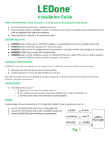
100W
WALLPACK LIGHT
9.10’’ x 18.50’’ x 9.40’’
D
E
F
C
1
2
3
4
B
A
3
2
1
5
C
D
4
6
7
8
A
B
SHEET 1 OF 1
SCALE:
TITLE:
MATERIAL:
DATE
SIGNATURE
NAME
DEBUR AND
BREAK SHARP
EDGES
FINISH:
UNLESS OTHERWISE SPECIFIED:
DIMENSIONS ARE IN MILLIMETERS
SURFACE FINISH:
TOLERANCES:
LINEAR:
ANGULAR:
Q.A
MFG
APPV'D
CHK'D
DRAWN
WEIGHT:
438
230
86.75
216.75
D
E
F
C
1
2
3
4
B
A
3
2
1
5
C
D
4
6
7
8
A
B
SHEET 1 OF 1
SCALE:
TITLE:
MATERIAL:
DATE
SIGNATURE
NAME
DEBUR AND
BREAK SHARP
EDGES
FINISH:
UNLESS OTHERWISE SPECIFIED:
DIMENSIONS ARE IN MILLIMETERS
SURFACE FINISH:
TOLERANCES:
LINEAR:
ANGULAR:
Q.A
MFG
APPV'D
CHK'D
DRAWN
WEIGHT:
D
E
F
C
1
2
3
4
B
A
3
2
1
5
C
D
4
6
7
8
A
B
SHEET 1 OF 1
SCALE:
TITLE:
MATERIAL:
DATE
SIGNATURE
NAME
DEBUR AND
BREAK SHARP
EDGES
FINISH:
UNLESS OTHERWISE SPECIFIED:
DIMENSIONS ARE IN MILLIMETERS
SURFACE FINISH:
TOLERANCES:
LINEAR:
ANGULAR:
Q.A
MFG
APPV'D
CHK'D
DRAWN
WEIGHT:
MOUNTING INSTRUCTIONS
SUITABLE FOR WATTAGES:
FIGURE 1
FIGURE 2
FIGURE 3
VER01.16
MOUNTING INSTRUCTIONS:
1. Open xture using two screws and housing will hinge open
J-BOX MOUNTING INSTRUCTIONS:
1. Drill or knock-out desired holes in bosses provided on casting
backside
2. Remove plug from wiring access hole and place gasket behind
back casting
3. Thread wire through housing and make wire connections in j-box
(not provided)
4. Position xture over j-box and fasten securely
5. Apply outdoor rates silicone caulking (not provided) around the
j-box/xture joint to prevent water ingress
SURFACE MOUNTING INSTRUCTIONS:
1. Drill or knock-out desire mounting holes
2. Drill matching holes on mounting using template
3. Secure xture to mounting surface with gasket provided between
housing and wall
4. Make necessary wiring connection inside xture
5. Apply outdoor rated silicone caulking (not provided) around the
surface and xture joint to prevent water ingress
FIXTURE IS SUITABLE FOR WET LOCATION
CAUTION: For proper weatherproof function all gaskets must be seated properly and all screws inserted and tightened rmly. Apply weatherproof
silicone sealant (NOT included) around the edge of the Wall Box and/or Junction Box. This is especially important with an uneven wall surface.
Silicone all plugs and unused conduit entries.
IMPORTANT: READ BEFORE REMOVING FIXTURE FROM CARTON. RETAIN FOR FUTURE REFERENCE.
This xture must be wired and installed in accordance with the NATIONAL ELECTRIAL CODE and all state and applicable local codes and
ordinances. These codes and ordinances supersede any and all instruction contained herein. Installation should be performed only by a licensed
and bonded electrician and a person familiar with the construction and operation of the product and the hazards involved in the installation and
operation of this product. Proper grounding is required for safety. Make certain power is OFF before installing or maintaining xture. Failure to
do so may increase the RISK OF PERSONAL INJURY, PROPERTY DAMAGE, FIRE, AND DEATH. The manufacturer takes no responsibility for the
product not installed under those guidelines and those contained in this document. See wiring diagram on back
9.40 in
238 mm
9.10 in
230 mm
9.40 in
238 mm
18.50 in
469 mm

MOUNTING INSTRUCTIONS
SUITABLE FOR WATTAGES:
ON-OFF WIRING METHOD:
Universal voltage driver permits operation at 120V through 277V, 50 or
60 Hz. Units ordered with (480V) sufx are 480V, 60Hz. For Non-Dimming,
follow the wiring directions as in FIG. 1
1. Connect the GROUND wire from xture to supply ground
2. Connect the white xture lead to the (-) COMMON supply lead
3. Connect the black xture lead to the (+) LINE supply lead
0-10V DIMMABLE WIRING METHOD:
Universal voltage driver permits operation at 120V through 277V, 50 or 60
Hz. For 0-10V Dimming, follow the wiring directions as in gure 2
1. Connect the GROUND wire from xture to supply ground
2. Connect the white xture lead to the (-) COMMON supply lead
3. Connect the black xture lead to the (+) LINE supply lead
4. Connect the purple xture lead to the (V+) DIM lead
5. Connect the gray xture lead to the (V-) DIM lead
5. Cap the yellow xture lead, if present. DO NOT connect
FIGURE 1
FIGURE 2
TROUBLESHOOTING:
1. Check that the line voltage at xture is correct
2. Is there voltage at the lamp xture wires? If there is no voltage, check
all connections
3. Ensure that the xture is grounded properly
VER01.16
LIGHTING
FIXTURE
(+) LINE
(-) COMMON
GROUND
BLACK
WHITE
GROUND
LIGHTING
FIXTURE
(+) LINE
(-) COMMON
(+)DIM V+
BLACK
WHITE
PURPLE
GROUND
GRAY
YELLOW
GROUND
(-)DIM V-
100W
WALLPACK LIGHT
/