Page is loading ...

Aerotech, A Munters Company
4215 Legion Dr. Mason, MI 48854-1036 USA
(517) 676-7070 Fax (517) 676-7078
Thank you for purchasing an Aerotech, A Munters Company Evaporative Cooling System. Aerotech
equipment is designed to be the highest performing, highest quality equipment you can buy. With
the proper installation and maintenance it will provide many years of service.
Section Page
USER'S MANUAL and INSTALLATION GUIDE
FORM QM1140
Rev. 2, July 2006
Page 1 of 36
TABLE OF CONTENTS
THANK YOU
PLEASE NOTE
Tools Required for Installation .................................................................................................2
Unpacking the Cooling System.............................................................................................. 2-3
Installation ............................................................................................................................ 3-23
Caulking............................................................................................................................... 17-19
Plumbing.............................................................................................................................. 24-28
Flush Out Kit (EC1507) purchased separately ........................................................................28
Elevation Views and Parts List for EC1609 & EC1640 Tank Kits ......................................... 29-32
System Start-Up .....................................................................................................................33
System Operation and Adjustment .........................................................................................33
Maintenance ...........................................................................................................................34
Maintenance Checklist............................................................................................................34
Warranty Statement................................................................................................................34
Exploded View and Parts List for CP system ...................................................................... 35-36
Aerotech CP
Evaporative Cooling System
with Center Tank
EC1609 & EC1640
To achieve maximum performance and insure long life from your Evaporative Cooling System it is
essential that it be installed and maintained properly. Please read all instructions carefully before
beginning installation.

Caulk Gun Hand Saw Hack Saw
5
/16" Socket or Nut Driver Clean Rags 1
3
/8" dia. hole saw
3
/8" Socket or Nut Driver Sharp Utility Knife Electric or Cordless Drill
9
/16" Socket or Nut Driver Tape Measure Phillips Screwdriver
7
/16" Wrench
TOOLS REQUIRED FOR INSTALLATION
UNPACKING COOLING SYSTEM
FORM: QM1140
Rev. 2, July 2006
Page 2 of 36
Aerotech, A Munters Company
4215 Legion Dr. Mason, MI 48854-1036 USA
(517) 676-7070 Fax (517) 676-7078
Aerotech Evaporative Cooling Systems come in lengths from 5'L.to 80'L., sold in multiples of 5'L. and 10'L.
modular sections. The ending kits, pumps, tank kits and plumbing kits will be packaged separately.
A CP10, CP20, CP30....CP70 and CP80 will arrive as multiples of 10'L. packages for the cooling frame and
Ending Kit.
Example: CP60 Cooling System
6 - CN10, 10'L. Cooling Frame
1 - EC4110, Ending Kit
1 - Sealant box
A CP5, CP15, CP25....CP65 and CP75 will arrive as multiples of 10'L. packages and one 5'L. package and
Ending Kit.
Example: CP65 Cooling System
6 - CN10, 10'L. Cooling Frame
1 - CN05, 5'L. Cooling Frame
1 - EC4110, Ending Kit
1 - Sealant box
If optional add on kits are ordered one or more extra box(s) marked CN02 or CN04 will be included.

FORM: QM1140
Rev. 2, July 2006
Page 3 of 36
Each CP System includes:
8" Pipe, PVC
Drip Collector, PVC
Distribution Cap, PVC
Pad Retainer, PVC
1
1
/2" Pipe with holes, PVC
1
1
/2" Slip Cap, PVC
2 - End Panels, left / right, Plastic
Pipe Support Brackets - supplied for 4' O.C. (see Chart A)
1 - Hardware Package
2 - Flush Out Kit (EC1507), purchased separately
Before beginning installation, check the overall condition
of the equipment. Remove packing materials, and examine
all components for signs of shipping damage. Any shipping
damage is the customer's responsibility and should be
reported immediately to the freight carrier.
1) Construct a wall opening according to your cooling system size,
with studs 2' O.C. or post 4' O.C. (max 5' O.C.). See Figure 1.
(For example a CP36 with EC1115 would have an opening of
36'
1
/2" L. x 64" H.).
INSTALLATION INSTRUCTIONS
Figure 1
Pad Height + 4"
2 x 4
Treated
Framing
2 x 10 Treated
Framing
2 x 4 Treated Framing (Install Level)
Pad Height + 4"
Pad Length + ½"
NOTE: Tank Kits must be purchased with each 'CP' Cooling
System.
Submersible pumps
15" Tank: EC1609
Black Poly Tank: EC1640
Wall Studs or
Posts
Pad Height + 14
1
/2"
Pad Height
Pad Height + 4"
6
1
/8"
1
1
/2"
8
1
/2"
See
Chart A
Page 4
48" 48" O.C. Typical
Extra Stud
or Post for
Left or Right
end Framing
(if necessary)
2 x 10 Treated Framing
(install level)
Anchor securely with
bolts or lag screws
9
1
/4"
EC1101
EC1102
EC1103
EC1115
EC1104
24"H
36"H
48"H
60"H
72"H
Catalog
No.
Pad
Height
28"H
40"H
52"H
64"H
76"H
Wall Opening
Height
Aerotech, A Munters Company
4215 Legion Dr. Mason, MI 48854-1036 USA
(517) 676-7070 Fax (517) 676-7078
1 x 4 x 6"L.
Blocking
1 x 4 x 6"L.
Blocking

FORM: QM1140
Rev. 2, July 2006
Page 4 of 36
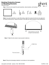
2) Some brackets are in the ending kit and some in
the cooling kit. Find 2 halves of the pipe bracket,
EC1330 and EC1328, and slide them together.
See Figure 2.
3) For proper pipe support bracket spacing refer to
Chart A, Figures 3A and 3B.
IMPORTANT!
The tee and cap must be setting evenly
on the ground or supported securely
on a level surface.
48" 48" O.C.
typical
48"
White Pipe Tank setting
on ground or level
surface
Figure 3B
Figure 2
EC1330, bracket with
mounting holes
2"
2"
Aerotech, A Munters Company
4215 Legion Dr. Mason, MI 48854-1036 USA
(517) 676-7070 Fax (517) 676-7078
Figure 3A
48"
EC1328, bracket
without holes,
may substitute
with EC1330
with holes
Chart A
Length of
Cooling
System
No of
Brackets
Needed
Placement
of
Brackets*
4' 2 2"
5' 2 12"
6' 2 12"
8' 3 2"
10' 3 12"
12' 4 2"
14' 4 12"
15' 5 2"
16' 5 2"
18' 5 12"
20' 6 2"
22' 6 12"
24' 7 2"
25' 7 12"
26' 7 12"
28' 8 2"
30' 8 12"
32' 9 2"
34' 9 12"
35' 10 2"
36' 10 2"
38' 10 12"
40' 11 2"
42' 11 12"
44' 12 2"
45' 12 12"
46' 12 12"
48' 13 2"
50' 13 12"
52' 14 2"
54' 14 12"
55' 15 2"
56' 15 2"
58' 15 12"
60' 16 2"
62' 16 12"
64' 17 2"
65' 17 12"
66' 17 12"
68' 18 2"
70' 18 12"
72' 19 2"
74' 19 12"
75' 20 2"
76' 20 2"
78' 20 12"
80' 21 2"
*Placement inches from each end
48" 48" O.C.
typical
12"
12" 48" 48"
Black poly tank setting on
ground or level surface

FORM: QM1140
Rev. 2, July 2006
Page 5 of 36
Figure 4A
2 x 4 Treated
Framing
Pipe Support Bracket
2 x 4 Treated Framing
2 X 10 Treated Framing
Pad Height + 4"
Pad Length + ½"
48" 48" O.C. Typical
4) At the bottom framing fasten the pipe support bracket to the 2 x 10 at each post (stud) according to the
proper spacing on Chart A. Make sure the lip of the pipe support bracket hangs on the top of the 2 x 10. The
top hole of the pipe support bracket should be secured with a
3
/8" x 3
1
/2" Lag screw (provided). Pre-drill
framing for
3
/8" Lag screws using
1
/4" drill bit. The bottom hole should be fastened with a #14 x 1
1
/2" Lag
screw (provided). See Figure 4A, 4B and 4C. If framing does not match Figure 4A, framing must be capable
of supporting 300 lbs. per bracket.
Pad Height + 4"
Figure 4B
2 x 10
Treated
Framing
2"
Lip of Pipe Support Bracket
3
/8" x 3
1
/2" Lag Screw
EC1330
#14
x 1
1
/2" Lag Screw
2 x 10 Treated Framing
2 x 4 End
Framing
2"
48"
Pipe
Support
Bracket
Figure 4C
Aerotech, A Munters Company
4215 Legion Dr. Mason, MI 48854-1036 USA
(517) 676-7070 Fax (517) 676-7078
EC1328,
bracket without
holes, may
substitute with
EC1330
1 x 4 x 6"L
Blocking
1 x 4 x 6"L
Blocking

Figure 5A
2 x 4
Treated
Framing
Figure 5C
Pipe Support
Bracket
2 x 4
Treated
Framing
8" Pipe Reservoir
4"
4"
2 x 10 Treated
Framing
5) Find the center of the cooling system and lay the 8" x 8" x 8" tee on the ground between 2 pipe support brack-
ets. Place 2 full sections of 8" pipe in pipe support brackets, one on each side of the 8" tee. See Figure 5A.
Prepare the pipe with PVC Pipe Primer, following directions of use and drying. After priming, use heavy duty,
heavy bodied PVC cement for pipe 8" diameter or larger, in accordance to the PVC cement directions.
6) Apply a generous amount of PVC cement to the inside of the belled end of tee, and the outside of the male
end of the pipe, and slide together, 5" deep. See Figure 5B. Continue for all sections of 8" pipe.
FORM: QM1140
Rev. 2, July 2006
Page 6 of 36
5"
Figure 5B
Aerotech, A Munters Company
4215 Legion Dr. Mason, MI 48854-1036 USA
(517) 676-7070 Fax (517) 676-7078
7) On each end of the cooling system extend the 8" pipe 4" past the edge of the framed opening. See
Figure 5C. If needed use the pipe cut off from one end to extend the other end far enough.
Pipe Support
Bracket
8" x 8" x 8" Tee
8" Pipe

FORM: QM1140
Rev. 2, July 2006
Page 7 of 36
Aerotech, A Munters Company
4215 Legion Dr. Mason, MI 48854-1036 USA
(517) 676-7070 Fax (517) 676-7078
8) Starting with a 12'L. drip collector find the center of it and
make 2 cuts in the front edge as shown in Figure 6A & 6B.
Set this drip collector on the 8" pipe with the notch over the
8" tee. Place a level across the drip collector flanges and
level drip collector front to back. Also be sure to keep 8" tee
level. See Figure 6C.
9) Carefully lift end of drip collector off 8" pipe. Prime and PVC
cement a 3" wide area on 8" pipe, at both ends of collector.
Replace drip collector on the 8" pipe, keeping it level. Fasten
each end of collector to 8" pipe using (1) #10 x 1
1
/4" TEK
screw located 4" from each end. See Figure 6D and 6E.
Figure 6B
1
1
/2"
5
1
/4"
3
1
/4"
Figure 6A
1
1
/2"
Front edge
of drip
collector
8" Pipe Reservoir
Pipe Support
Bracket
2 x 10
Treated
Framing
PVC cement 3" each end of drip collector
Figure 6D
4"
Notch cut in center of Drip Collector
8" Tee
#10 x 1
1
/4" TEK Screw
Figure 6C
8" Tee
Pipe Support
Bracket
2 x 10 Treated
Framing
Level
Drip Collector
Figure 6E
8" Tee
Pipe Support
Bracket
2 x 10 Treated
Framing
Drip Collector
#10 x 1
1
/4" TEK Screw at 4"
from each end of drip collector

16"
O.C.
16"O.C.
Typical
#10 x 1
1
/4" TEK Screw
Figure 7B
16"O.C.
2"
FORM: QM1140
Rev. 2, July 2006
Page 8 of 36
Aerotech, A Munters Company
4215 Legion Dr. Mason, MI 48854-1036 USA
(517) 676-7070 Fax (517) 676-7078
10a) Starting 2" from each end of the 8" tee, keeping
drip collector level, fasten front edge of drip
collector to 8" pipe using #10 x 1
1
/4" TEK screw
(provided). Continue fastening drip collector to 8"
pipe using #10 x 1
1
/4" TEK screws at 16"O.C., use
the V-groove as a guide. See Figures 7A and 7B.
Refer to Step 14 for
caulking procedures.
Figure 7A
Pipe
Support
Bracket
Drip Collector
#10 x 1
1
/4"
TEK Screw
Level
2"
16"O.C.
Typical

Figure 7C
Drip Collector
Drip Collector Splice
8" Pipe
PVC Cement 3" on each
side of Drip Collector
#10 x 1
1
/4" TEK Screw
10b) Continue placing drip collectors down length of pipe by leveling, priming, cementing and fastening drip
collectors to 8" pipe. Be sure to push drip collectors tight together. See Figure 7C. Leave an
1
/8" gap
between edge of framed opening and drip collector on each end.
10c) Prime and PVC cement drip collector 3" on each side of joint. Center splice over joint in drip collector and
fasten in place using (6) #10 x 1
1
/4" TEK screws. Locate (2) in bottom of splice and (2) on each flange.
See Figures 7C and 7D.
Refer to Step 15 for
caulking procedures.
Figure 7D
#10 x 1
1
/4" TEK Screw
Drip
Collector
Drip Collector Splice
8" Pipe
FORM: QM1140
Rev. 2, July 2006
Page 9 of 36
Aerotech, A Munters Company
4215 Legion Dr. Mason, MI 48854-1036 USA
(517) 676-7070 Fax (517) 676-7078

FORM: QM1140
Rev. 2, July 2006
Page 10 of 36
Aerotech, A Munters Company
4215 Legion Dr. Mason, MI 48854-1036 USA
(517) 676-7070 Fax (517) 676-7078
Remove all shavings
from inside the pipe
and from the top of
drip collector.
WARNING
!
Figure 8B
8" Pipe Reservoir
Drip
Collector
Drain Fitting, PVC
cement into place
24" O.C.
Typical
12"
11) Starting 12" from left end of drip collector, use a 1
3
/8" dia. hole saw and drill a hole through the drip
collector and 8" pipe every 24"O.C. Make sure not to leave plugs from drilling hole in the pipe. PVC
cement drain fitting, into hole. See Figures 8A and 8B.
Figure 8A
Drip Collector
Drain Fitting, PVC
cement into place

FORM: QM1140
Rev. 2, July 2006
Page 11 of 36
Aerotech, A Munters Company
4215 Legion Dr. Mason, MI 48854-1036 USA
(517) 676-7070 Fax (517) 676-7078
12b) Slide the rubber bellow connector over the 8" pipe and the other end over the black poly tank. Be sure the
drip collector remains on top of the 8" pipe. Secure in place with hose clamps positioned in the grooves of
the rubber bellow connector. Install the 8" rubber cap on the 8" pipe end opposite the tank. See Figures 9B
through 9D.
Figure 9B
8" x 7.75"L. pipe
Rubber bellow
connector
Ground or other support must be
capable of supporting 300 lbs.
Black poly
tank
Black Poly Tank:
12a) Prepare the black poly tank for attachment to the 8" pipe by removing the flat interior surface of the 8" pipe
area, cut the flat end leaving a minimum of
1
/4" lip around the edge, See Figure 9A. DO NOT CUT the
outer surface of the 8" pipe area, cutting the round surface will weaken the tank structure. See Figure 9A.
Before Cut
Cut the flat end,
leaving
1
/4" lip
Flat interior surface
to be trimmed
1
/4"
After Cut
Trimmed
out interior
surface
Figure 9A
Flat interior surface
to be trimmed
8" pipe area
Outer surface
For Black Poly Tank proceed to Step 12a. For White Pipe Tank proceed to Step 13a.
NOTE: In some installations
it may be necessary to bury
or elevate the black poly tank
for proper alignments with the
8" pipe; in either case the
ground or other support must
be capable of supporting 300
lbs. If using the optional
'EC1630, Cooling Tank Drain
Kit-below grade' install at this
time following the instruc-
tions provided with the kit.

FORM: QM1140
Rev. 2, July 2006
Page 12 of 36
Aerotech, A Munters Company
4215 Legion Dr. Mason, MI 48854-1036 USA
(517) 676-7070 Fax (517) 676-7078
FD244:
Figure 9D
TANK BURIED
Figure 9C
TANK ON GROUND
Ground or other support must be
capable of supporting 300 lbs.
Ground or other support must be
capable of supporting 300 lbs.
Rubber bellow connector
with hose clamps
Black poly tank
8" x 7.75"L. Pipe Nipple
Rubber bellow connector
with hose clamps
Black poly tank
Non-trimmed area
Trimmed 8" pipe area
11.75"
approx.
Non-trimmed area
Trimmed 8" pipe area
Pipe with Drip Collectors
8" x 8" x 8" Tee
8" x 7.75"L. Pipe Nipple
Pipe with Drip Collectors
8" x 8" x 8" Tee
2" x 10" Treated
Framing
2" x 10" Treated
Framing
FD244:

White Pipe Tank:
13a) Prepare the tee, pipe nipples and pipe cap in accordance to PVC primer and cement directions and
assemble the (2) pipe nipples, tee and pipe cap. See Figure 10A. For completed assembly, See Figure 10B.
15" x 7.75"L.
Pipe
Tee
15" Pipe
Pipe Cap
Hole for Overflow
8" x 7.75"L. Pipe
Figure 10A
Figure 10B
EC1609, 15" TANK KIT
(COMPLETED)
15" Slip Cap
15" x 28"L. Pipe
15" x 15" x 8" Tee
15" x 7.75"L. Pipe
8" x 7.75" Pipe
Hole for
Overflow
FORM: QM1140
Rev. 2, July 2006
Page 13 of 36
Aerotech, A Munters Company
4215 Legion Dr. Mason, MI 48854-1036 USA
(517) 676-7070 Fax (517) 676-7078

FORM: QM1140
Rev. 2, July 2006
Page 14 of 36
Aerotech, A Munters Company
4215 Legion Dr. Mason, MI 48854-1036 USA
(517) 676-7070 Fax (517) 676-7078
Figure 10D
PIPE CAP BURIED
13b) Once the PVC cement has dried
use primer and cement and
assemble the tee fully onto pipe.
Be sure the drip collectors remain
on top and the tee is straight up
and down. When tee is
completely installed the 28" pipe
nipple with cap may be buried so
that when together it rests on the
ground or another support. See
Figures 10C and 10D. Install 8"
cap on each end of cooling
system. See Figure 10E.
Figure 10C
PIPE CAP ON GROUND
15" x 7.75"
Pipe Nipple
15" x 28"L. Pipe
Nipple
Pipe Cap
Tee
8" x 7.75"L. Pipe Nipple
30"
approximately
Hole for Overflow
Pipe with
Drip
Collectors
Ground or other support
must be capable of
supporting 300 lbs.
8" x 8" x 8" Tee
Pipe Cap
Tee
Pipe with Drip
Collectors
Hole for Overflow
Ground or other support must be
capable of supporting 300 lbs.
15" x 7.75" Pipe Nipple
15" x 28"L. Pipe
Nipple
8" x 7.75"L. Pipe Nipple
8" x 8" x 8" Tee
8" End
Cap
8" End Cap
Pipe Reservoir
Figure 10E

FORM: QM1140
Rev. 2, July 2006
Page 15 of 36
Aerotech, A Munters Company
4215 Legion Dr. Mason, MI 48854-1036 USA
(517) 676-7070 Fax (517) 676-7078
4
3
/4", Trim Ribs
on Both Sides
Ribs to be trimmed
Length of End Panel
1
7
/8"
1
7
/8"
Smooth side out
Figure 11A
LEFT END PANEL
14a) Determine the height of your cooling system and cut the end panels down to the correct length according
to Chart B. Trim the end panels as indicated below. If 2 EC1507 Flush-Out Kits are purchased, then drill
a 2" - 2
1
/4" dia. hole in each end panel also. See Figure 11A and 11B.
2" - 2
1
/4" Dia. hole for Flush
Out Kit
Smooth side out
Figure 11B
RIGHT END PANEL
Groove side in
Groove side in
27
1
/4"
39
1
/4"
51
1
/4"
63
1
/4"
75
1
/4"
24"H
36"H
48"H
60"H
72"H
Chart B
Length of
End Panel
Pad
Height
Ribs to be trimmed
2" - 2
1
/4" Dia. hole for
Flush Out Kit (if ordered
separately)
4
3
/4"
Trim
Ribs on
Both
Sides
Length of End Panel
BEFORE CUTTING
AFTER CUTTING
NOTE: Smooth side of end panel is
the outside of system (Figure 11A).
Grooved side of end panel is
facing the pad (Figure 11B).
BEFORE CUTTING
AFTER CUTTING
2
3
/4"
2
3
/4"

FORM: QM1140
Rev. 2, July 2006
Page 16 of 36
Aerotech, A Munters Company
4215 Legion Dr. Mason, MI 48854-1036 USA
(517) 676-7070 Fax (517) 676-7078
14b) Apply PVC cement to left end of drip collector. On left side of system line up the 3 holes in the drip
collector end cap to the 'U' Channels in the drip collector, fasten using (3) #10 x 1
1
/4" TEK screws
(provided). See Figure 11C.
14c) Slide left end panel into framing and into drip collector on left end. End panel should fit snug, make sure
ribs sit down tight into the drip collector. Fasten the last 2 screws into the drip collector end cap using (2)
#10 x 1
1
/4" TEK screws. See Figure 11E.
14d) Hold the end panel tightly against the framing and attach end panel to framing using #10 x 1
1
/4" TEK
screws (provided), See Figure 11D. See Chart C for spacing and number of Lag screws provided.
Spacing
1
2
2
3
3
24"H
36"H
48"H
60"H
72"H
24"O.C.
18"O.C.
24"O.C.
20"O.C.
24"O.C.
No. of
Screws
Pad
Height
Chart C
Spacing
top to first
screw
2"
2"
2"
2"
2"
PVC cement must be completely
dried before filling system with water.
Failure to do so may result in pipe
and tee sections coming apart.
WARNING
!
Figure 11D
End Panel
(smooth side)
2 x 4 Treated
Framing
Drip
Collector
#10 x 1
1
/4"
TEK Screw
Drip
Collector
End Cap
#10 x 1
1
/4"
TEK Screw
See Chart C
#10 x 1
1
/4"
TEK Screw
Figure 11C
Drip
Collector
U-Channel
(3 total)
#10 x 1
1
/4"
TEK Screw
Drip
Collector
End Cap
Drip Collector
End Cap
Figure 11E
2 x 4 Treated
Framing
PVC
cement
end of
drip
collector
V Groove
NOTE: Bottom lag screw will be between
20" -25" from bottom of end panel.

FORM: QM1140
Rev. 2, July 2006
Page 17 of 36
Aerotech, A Munters Company
4215 Legion Dr. Mason, MI 48854-1036 USA
(517) 676-7070 Fax (517) 676-7078
15a) Using caulk provided, start at left end and caulk inside and outside of end panel and drip collector end
cap where they meet drip collector and 8" pipe. Also caulk the screw head in bottom of drip collector and
screws coming in thru end panel. See Figure 12A & 12B.
15b) Working down the length of the cooling, apply a wide bead of caulk at each edge of drip collector splices.
Be sure to form caulk around all surfaces and over TEK screws. Caulk over TEK screws should be at
least
3
/4" diameter in size. Apply a bead of caulk around each drain fitting in drip collector. See
Figure 12C.
15c) Refer to Step 18 for further caulking of distribution cap and right end panel.
Figure 12C
VIEW FROM ABOVE
Drip Collector
Caulk over
TEK screws
Wide bead of caulk at edges of Drip Collector
Splice
Caulk around
each drain fitting
8" Pipe
Caulk over each
TEK screw
Figure 12B
View from Inside
End Panel
Caulk inside of
end panel &
around screws
8" Pipe
#10 x 1
1
/4"
TEK Screw
Drip Collector
Figure 12A
View from Outside
Drip Collector
2 x 4
Treated
Framing
End Panel
(smooth
side)
Caulk end panel and
around drip collector
end cap

Figure 13C
Left End
Panel
Distribution Cap
Left Side
2 x 4
Framing
#14 x 1
1
/2"
Lag Screw
FORM: QM1140
Rev. 2, July 2006
Page 18 of 36
Aerotech, A Munters Company
4215 Legion Dr. Mason, MI 48854-1036 USA
(517) 676-7070 Fax (517) 676-7078
16) Attach distribution cap to left end of framed opening using #14 x 1
1
/2" Lag screws and bushings. DO NOT
tighten Lag screw against distribution cap. Distribution cap should be able to slide back and forth along slot to
allow for contraction and expansion. Be sure to hold
distribution cap tight against framing and that the Lag
screws go in square so as not to tip cap upward.
See Figures 13B and 13C. Repeat Step 16, leaving
a
1
/4" gap between sections, until you have installed
all distribution caps. See Figure 13A.
Figure 13D
Drip
Collector
End Cap
Distribution Cap
Drip Collector
#10 x 1
1
/4" TEK
screws
8" Pipe
17a) On right side of system apply
PVC cement to end of drip
collector and line up the 3 holes
in the drip collector end cap to
the 'U' Channels in the drip
collector, fasten using
(3) #10 x 1
1
/4" TEK screws
(provided). See Figure 13D.
Bushing
Distribution Cap
2 x 4 Treated
Framing
Distribution cap must be able to slide
in slot. DO NOT OVER TIGHTEN lag
screws. Install similar to vinyl siding.
IMPORTANT
!
Figure 13A
Distribution Cap
Figure 13B
1 x 4 x 6"L. Blocking
Distribution
Cap
2 x 4 Treated Framing
#14 x 1
1
/2" Lag Screw
Bushing

Drip Collector
FORM: QM1140
Rev. 2, July 2006
Page 19 of 36
Aerotech, A Munters Company
4215 Legion Dr. Mason, MI 48854-1036 USA
(517) 676-7070 Fax (517) 676-7078
17b) Slide right end panel into framing and into drip collector on right end. End panel should fit snug, make
sure ribs sit down tight into the drip collector. Fasten the last 2 screws into the drip collector end cap
using (2) 10 x 1
1
/4" TEK screws. See Figure 13E.
17c) Hold the end panel tightly against the framing and attach end panel to framing using #10 x 1
1
/4" TEK
screws (provided), See Figure 13E. See Chart C, page 14 for spacing and number of Lag screws
provided.
18) Apply a bead of caulk around inside and outside of end panel and drip collector end cap where the end panel
meets the drip collector and 8" pipe. See Figure 13E and 13F. Also caulk the screw head in bottom of drip
collector and screws coming in thru end panel.
Figure 13E
Caulk
Joint
Right End
Panel
Drip Collector
8" Pipe
Caulk joint and
around screws
Right End
Panel
Drip Collector
End Cap
Distribution
Cap
8" Pipe
#10 x 1
1
/4"
TEK Screws
IMPORTANT!
Recheck all caulk joints, before
proceeding, to insure everything is
sealed. Add caulk if necessary.
Figure 13F

FORM: QM1140
Rev. 2, July 2006
Page 20 of 36
Aerotech, A Munters Company
4215 Legion Dr. Mason, MI 48854-1036 USA
(517) 676-7070 Fax (517) 676-7078
18) Pipe support snaps onto distribution cap, start 12" from end and space every 24". See Figure 14A. Five (5)
supports per 10' section of distribution cap. Pipe supports can be slid back and forth for proper alignment.
20) Find the 1
1
/2" Slip Tee, it will be mounted directly above the 8" x 8" x 8" Tee (centered), then working each
way from the 1
1
/2" Tee, slide pipe supports in distribution cap, to align. See Figure 14A & 14B. The section of
pipe with the slip cap will go on one end of the system and the slip cap found in the EC1609 Tank Kit will go on
the other end. For systems longer than 12', connect sections of pipe together keeping holes aligned. See
Figure 14B. Position pipe on pipe supports. Rotate pipe so that holes are straight upward (12 o'clock). See
Figure 14C.
21) Make sure caulk is dry and begin putting cooling pad in place, taking care to position pieces tight together. If
your pad has Directional Arrows, position arrows to point upward and to the inside of the building. See Figure
15. Continue this pattern, stopping at the next to the last piece of pad.
Figure 14A
Distribution Cap
2 x 4 Framing
Figure 14B
Slip Cap found in EC1609
8" x 8" x 8" Tee
Slip Cap
already
installed
on pipe
Figure 14C
Pipe Support
Distribution Pipe, with hole
pointing up
Distribution Cap
2 x 4 Framing
1
1
/2" Slip Tee
Drip
Collector
2 x 4
Treated
Framing
Left
End
Panel
Distribution Cap
Cooling Pad
8" Pipe Reservoir
Figure 15
2 x 4
Pipe Support
Pipe Support
Pipe
Support
12" 24"
/