Hilti DS WS10 Operating instructions

Type
Operating instructions
Operating instructions en
DS-WS 10
Printed: 07.07.2013 | Doc-Nr: PUB / 5069722 / 000 / 00
2
Printed: 07.07.2013 | Doc-Nr: PUB / 5069722 / 000 / 00
3
Contents
1. General information 4
2. Description 5– 9
3. Tools and accessories 11–14
4. Technical data 15–18
5. Safety precautions 19–23
6. Preparing the saw system for use 25–34
7. Operating the equipment 35–38
8. Care and maintenance 39
9. Troubleshooting 41–44
10. Disposal 45
11. Manufacturer's warranty tools 46
12. EC declaration of conformity 47
ORIGINAL OPERATING INSTRUCTIONS
Printed: 07.07.2013 | Doc-Nr: PUB / 5069722 / 000 / 00
4
1. General information
The operating instructions must be read carefully
before the equipment is put into operation.
Always keep these operating instructions with the
equipment.
The wire saw system should be handed over to other
persons only complete with the operating instruc-
tions.
Indication of danger
CAUTION
This word is used to draw attention to a potentially dan-
gerous situation which could lead to minor personal
injury or damage to the equipment or other property.
Pictograms
1.2
Warning Caution: High voltage Warning: Avoid hand
injuries
Wear protective gloves
Wear protective footwear Wear respiratory protec-
tion
Read the operating
instructions before use
Wear protective goggles Wear a safety helmet
Compact wire saw
Air compressor with control panel
Compressed air hoses (2×7m,1×1m)
Positioning template
Water hoses (2×10 m)
Water nozzle, flexible
Water nozzle, long
Water hose connector with regulating valve
1
/
2
square drive wrench
Toolbox for tools and accessories
Information on how to use these operating
instructions
1.1
The wire saw system
1.3
Printed: 07.07.2013 | Doc-Nr: PUB / 5069722 / 000 / 00
5
2. Description
Description 2.1 Use as directed 6
2.2 Components 6
2.3 Operating controls 7
2.4 Drive principle 9
2.5 Saw advance and wire storage 9
2.6 Wire guidance 9
2.7 Safety concept for the working area 9
Printed: 07.07.2013 | Doc-Nr: PUB / 5069722 / 000 / 00
6
Use as directed
The DS-WS10 wire saw has been developed for the
technical demolition of steel, concrete, stone or brick-
work structures in construction and civil engineer-
ing applications. Use of the saw for other applica-
tions is considered to be “not as directed” and requires
prior approval by the manufacturer.
The operator in charge must be aware of the possi-
ble dangers and of his responsibility for safety, both
with regard to himself and to others.
The wire saw is designed for a maximum cutting
length of 2 meters. The maximum distance between
the pivoting pulleys at the machine and the wire entry
or exit point must not exceed 3 meters.
The wire saw may be operated only by specialists
trained in concrete cutting techniques, referred to in
the following as “operators”. These persons must be
familiar with the content of these operating instruc-
tions and must have been trained in their safe appli-
cation by a Hilti specialist.
National regulations and legislation as well as the
information in the operating instructions and safety
precautions concerning the saw and its accessories
(sawing wire, fastening accessories, lifting equip-
ment, compressor, hydraulic power unit etc.) must
be observed.
Do not use the saw to cut objects not secured in place
or held against the wire by hand.
Use of the wire saw or its components for purposes
other than wire sawing is prohibited, i.e. use as a
transport or conveyance device is not permissible.
2.1
2. Description
3
5
4
Components
2.2
Base plate
Guide rail and advance unit
Pivoting pulley crossbar
Drive unit
Guard
Wire storage extension
End stop
1
2
5
6
7
Printed: 07.07.2013 | Doc-Nr: PUB / 5069722 / 000 / 00
7
2. Description
Operating controls and parts
Base plate
Leveling screws
Anchor slot
Connecting taper
2.3
Guide rail and advance unit
Internal taper
Eccentric pin
Carriage locking mechanism
Manual advance mechanism
Piston rod securing clamp
Return lock
Compressed air connection
Drive unit interface and locking mechanism
End stop
Pivoting pulley crossbar
Attachment point and clamp
Pivoting pulley locking lever
Wire storage pulley
Guard mounting hole
Hollow axles
1
1
1
12
3
1
2
2
34 45 5
1
2
2
5
6
7
7
3
4
9
8
Printed: 07.07.2013 | Doc-Nr: PUB / 5069722 / 000 / 00
2. Description
Pneumatic system control panel
Advance direction control valve
Regulator for advance pressure adjustment
Advance pressure indicator
Securing band
Safety and operating instructions
Compressed air supply connection
Advance cylinder connection
Air compressor
Positioning template
Grip
Edge indicating line of cut
Wire entry point
Possible anchor positioning range
Optimum anchor position
Retaining magnet for attachment to base plate
Water connection and regulating valve
Coupling (water outlet from hydraulic unit)
Flow regulation and shut-off valve
Water hose connection (cooling water nozzles)
8
Guard
Guard mounting pin
Spring pin
12
Drive unit
Mounting interface
Hydraulic connection
Drive pulley
Return pulley
Carrying / holding bar
Guard guides
14 3
6
26 2 5
1
2
3
3
2
1
6
4
5
3
2
17
8
2 3 6 5 4
Printed: 07.07.2013 | Doc-Nr: PUB / 5069722 / 000 / 00
9
2. Description
Drive principle
The sawing wire is passed around the object to be cut,
over guide pulleys and the drive pulley before the ends
of the wire are joined to form an endless loop. The wire
loop is set in motion by rotation of the drive pulley and
pulled through the object to be cut by way of the linear
advance movement of the drive unit.
Saw advance and wire storage
Wire advance is by way of the “block and tackle” princi-
ple. The advance movement, i.e. causing the wire to be
drawn in, is effected by the pulleys being pushed apart
by a compressed air cylinder. In addition, the drive pul-
ley is mounted on a moving carriage. The length of wire
that can be stored on the pulleys depends whether a sin-
gle or double return system is used, i.e. with or without
the optional wire storage pulley. Please refer to the “Tech-
nical data” section for further details.
Wire guidance
Alignment of the sawing wire between the pivoting pul-
ley on the machine and the pivoting pulley mounted on
the object being cut can be set precisely by adjusting the
pulleys. In flush cutting applications, the pivoting pul-
leys adjust automatically to the decreasing distance
between the wire entry and exit points by pivoting freely
as the cut progresses.
2.6
2.5
2.4
Safety concept for the working area
2.7
357097
®
STOP
STOP
STOP
Store 1x = Start 1 bar
min. 1.6 m
max. 2.7/ 4.1 m
Store 2x = Start 2 bar
min. 2.3 m
max. 4.5/ 7.3 m
STOP
STOP
STOP
Guideline/Richtlinie
hydraulic
80–120 bar
max. 50 l/min
Printed: 07.07.2013 | Doc-Nr: PUB / 5069722 / 000 / 00
10
Printed: 07.07.2013 | Doc-Nr: PUB / 5069722 / 000 / 00
11
3. Tools and accessories
Tools and accessories 3.1 Sawing wire – safety precautions and instructions 12
3.2 Wire storage extension 12
3.3 Pulley stand 12
3.4 Release pulley 12
3.5 Sawing wires and accessories 13
3.6. Accessories for securing and operating the drive unit
and wire guides 14
Printed: 07.07.2013 | Doc-Nr: PUB / 5069722 / 000 / 00
12
3. Tools and accessories
Sawing wire
Safety precautions and instructions
Use only rubber- or plastic-coated sawing
wires of a type approved for use at a speed of at least
30 m/sec.
Connecting wires of different diameters togeth-
er, the use of worn, out-of-round wires or wires with
loose beads or damaged cores (individual strands bro-
ken) is not permissible.
Observe the wire and wire connector manu-
facturer’s instructions when connecting sawing wires.
Use only diamond wires with beads of a diam-
eter within the 8 – 12 mm range. Other diameters may
cause the wire to jump off the pulleys or result in dam-
age to the running surface of the pulleys.
3.1
Pulley stand
In applications where, due to restricted access, it is
impossible to mount the compact wire saw directly on
the object to be cut or where longer cuts of up to a max-
imum of 2 meters are to be made, the sawing wire is
guided to the cutting face by the pulley stand.
3.3
Release pulley
The release pulley is used to decrease the length of wire
in contact or to increase the radius of the arc followed
by the wire (avoiding a tight radius) at the rear of the
object to be cut.
3.4
Wire storage extension
The wire storage extension can be used to increase wire
storage capacity from 250 cm to 500 cm.
3.2
Printed: 07.07.2013 | Doc-Nr: PUB / 5069722 / 000 / 00
13
3. Tools and accessories
Hilti sawing wires and accessories
3.5
Special wires
(electroplated beads)
Standard diamond wires
(sintered beads)
DS-W10.5 diamond wires
Hilti DS-W10.5 diamond wires for DS-W15, DS-WS30 and DS-WS10 wire saw systems
Designation
Wire length DS-W 10.5 BC DS-W 10.5 LC DS-W 10.2 steel 20% DS-W 10.8 steel 100%
(m) 햲햳햴
10 m 235835/6 * 235834/9 *
14 m 235836/4 * 235838/0 * 376982/0 371987/9
18 m 315019/0 * 315020/8 * 371983/8 371988/7
22 m 315022/4 * 315023/2 * 371984/6 371989/5
26 m 315025/7 * 315026/5 *
30 m 315028/1 * 315029/9 *
50 m 370500/1 376630/0 371985/3 371990/3
100 m 370426/9 376631/8 371986/1 371991/1
150 m 376633/4 376632/6 373130/4
per/m 376635/9 376634/2 377830/5 377781/0
* with factory-fitted flexible connectors
Accessories for Hilti diamond wires
Designation Package Ordering Item no.
contents designation
Crimping pliers 1 DS-WSTHY
235845/5
For crimping connectors / repair sleeves
Flexible connectors 1 DS-WCMV
340427/4
Quick-release type
Set of flexible connectors 5 DS-WCSet
371383/1
Quick-release type with pin and O-ring
Pin 10 DS-WP 235842/2
Replacement pin for quick-release connectors
Sleeve 5 DS-WS
235841/4
Repair sleeve
O-ring 10 O-Ring 10/4,7×2,5 235844/8
Fitted between connector and bead
Crimping jaws 2 DS-WJ
340426/6
Replacement jaws for crimping pliers
Angle grinder 1 AG 125-S 000000/0
For cutting diamond wire
Recommendations: Which specification for which material?
Material
Desired characteristics
Reinforced concrete
Fast cutting Long life
Reinforced concrete
Heavily reinforced
concrete
Solid steel
BC LC Steel 20% Steel 100%
Special wires
(electroplated beads)
Standard diamond wires
(sintered beads)
Hilti wire saw type
Bead diameter (mm)
Diamond matrix thickness (mm)
No. of beads per meter
WSS30, WS15, WS10
10.5
1.5
44 40 40 48
––
10.810.2
BC LC Steel 20% Steel 100%
Technical data
Printed: 07.07.2013 | Doc-Nr: PUB / 5069722 / 000 / 00
14
3. Tools and accessories
Accessories for securing the drive unit and wire guides
3.6
Ordering designation Quantity Use
DS-WS tool set Wire saws
comprising:
Hilti plastic toolbox 1 Operator
Accessories, list of contents and uses 1 Operator
O
pen-end / ring wrench, 19 mm 1 Fastening pulley stand
Hammer, 1
1
/
2
kg 1 Setting anchors, assembly
Screwdriver, 6 mm 1 Clamping spindle
BB blow-out pump 1 Blowing out anchor holes
Folding rule, 2-metre 1 Operator
Spirit level 1 Operator
Wooden pencil 2 Operator
Cleaning cloth 1 Operator
Hilti spray 1 Operator
Hilti grease dispenser 1 Operator
Flat brush 1 Operator
Protective goggles 1 Operator
Clamping spindle, short, M12S 3 Pulley stand, drive unit
DD-CN-SML clamping nut 3 Pulley stand, drive unit
HSD-G M12 setting tool 1 Fastening anchors
Water connection nipple 1 Water supply
GK seal 5 Water seal for 356700/5
Steel wedge 6 Securing concrete blocks
Accessories and wearing parts for Hilti wire saw systems
Ordering designation Quantity Use
M12L clamping spindle, long 1 Fastening pulley stand, drive unit
HKD-D M12×50 flush anchor 50 Hole diameter 16 mm
Water supply, long 1 Water supply line
Water supply, flexible 1 Water supply line
DS-WSW200 guide pulley 1 Pulley stands, WS 15/WSS 30 drive
DS-WSW140 guide pulley 1 Plunge saw return pulley
DS-WSW500 drive wheel 1 DS-WSS 30 drive unit
DS-WSWD280 drive wheel 1 DS-WS15 drive unit
DS-WSWS280 storage pulley 1 DS-WS15 drive unit
DS-WSWS200 storage pulley 1 DS-WS15 drive unit
Cross-type tube clamp 1 Mounting guide pulleys
Double tube clamp 1 Tube extension
Tube, 2″×1 m (60.3 mm outside dia.) 1 Tube extension
CEE 32A coupling (female) 1 For extension cable
Round fuse, 3.15 A, 250 V, fast-acting 10 DS-WS15 control unit
Round fuse, 0.63 A, slow-acting 10 DS-WS15 control unit
Fuse, 250 V, 40 A 5 DS-WS15 control unit
DS-WSTHY crimping pliers 1 Crimping connectors and sleeves
DS-WCMV connector 1 Quick-release type
WS-WP pin 10 Spare pin for quick-release connector
DS-WS sleeve 5 Repair sleeve
O-ring, 10/4,7×2,5 10 Fitted between connector / bead
DS-WJ clamping jaws 2 Spare jaws for crimping pliers
Printed: 07.07.2013 | Doc-Nr: PUB / 5069722 / 000 / 00
15
4. Technical data
Technical data 4.1 Hydraulic drive 16
4.2 Compressed air supply 16
4.3 Cooling and flushing water supply 16
4.4 Dimensions and weights 16
4.5 Performance data 17
4.6 Wire storage capacity and length requirements 17
4.7 Type plate 18
4.8 Noise levels 18
Printed: 07.07.2013 | Doc-Nr: PUB / 5069722 / 000 / 00
16
4. Technical data
Hydraulic drive
The DS-WS 10 compact wire saw is designed for oper-
ation with the Hilti D-LP 15 and D-LP 32 or D-LP 30
hydraulic power units. Use of other hydraulic units for
powering the saw is permissible only when such units
are of a suitable specification and type approved for use
as a power source for hydraulic drilling or sawing equip-
ment.
Flow rate: max. 50 l/min.
Optimum working range: 36 to 50 l/min.
Pressure: max. 210 bar
Optimum working range: 80 to 120 bar
A built-in safety device limits the oil flow rate to the
hydraulic motor to a maximum of 50 l/min., thus limit-
ing the wire speed to a maximum of 27 m/sec.
The operator will notice when the flow rate limiting device
has become active as the drive unit then no longer runs
smoothly (audible and visual indication).
.
Do not, under any circumstances, operate the saw at a
flow rate in excess of 50 l/min.
Compressed air supply
The compressor for the air supply is included as part of
the wire saw system.
Pressure: 6 to 8 bar
Flow rate: 205 l/min
If a different compressor is used, ensure that its speci-
fication is suitable and that it is of a type approved for
use on construction sites.
Cooling and flushing water supply
Please follow the instructions for your hydraulic power
unit.
4.3
4.2
4.1
Dimensions and weights
Dimensions of the compact wire saw
Weight: 69.5 kg
4.4
495
692
1221
1970
536
Dimensions of the compressor with control panel
Weight: 20.1 kg
265
497
185
563
508
Printed: 07.07.2013 | Doc-Nr: PUB / 5069722 / 000 / 00
17
4. Technical data
Dimensions of single-pair pulley stand
Weight: 21.3 kg
335
max. 605
454
470
593
275
421
Length of system compressed air line:
Length of system compressed air line: 7 m
Length of system water supply line: 10 m
Performance data
Nominal power at 120 bar and 50 l/min: 10 kW
Wire speed at max. 50 l/min.: 27 m/sec
4.5
Wire storage capacity and length requirements
Rigging method A B C D
Storage rigging single single double double
Storage extension without with without with
Wire on drive, min. 160 cm 160 cm 230 cm 230 cm
Storage capacity 110 cm 250 cm 220 cm 500 cm
Wall thickness, max. 55 cm 125 cm 110 cm 250 cm
4.6
Printed: 07.07.2013 | Doc-Nr: PUB / 5069722 / 000 / 00
18
4. Technical data
®
Registered trademark of Hilti Corp. Schaan, Liechtenstein
Made in Austria
DS-WS10
357072
Nominal power rating: max. 17.5 kW
Oil flow rate: max. 50 l/min
Oil pressure: max. 210 bar
Drive pulley dia.: 280 mm
Speed: max. 1900 r.p.m.
Diamond wire dia.: 8–12 mm
xxxxxx
xx 03xxxxxxxxxxxx
Type plate
4.7
Noise levels
Typical A-weighted
sound power level as per ISO 3744:
DS-WS10 with D-LP15 102.0 dB(A)
DS-WS10 with D-LP32 103.5 dB(A)
Typical A-weighted
sound pressure level
at the workplace
at a distance of 3 m
as per ISO 11202:
DS-WS10 with D-LP15 83.5 dB(A)
DS-WS10 with D-LP32 84.5 dB(A)
The use of ear protection is recommended!
4.8
Printed: 07.07.2013 | Doc-Nr: PUB / 5069722 / 000 / 00
19
5. Safety precautions
Safety precautions 5.1 Safety measures at the working area 20
5.2 Preparations 20
5.3 Securing the objects being cut and disposal of sawing slurry 21
5.4 Operating safety 21
5.5 Electrical safety 22
5.6 Safety precautions during transport 22
5.7 General safety information 23
Printed: 07.07.2013 | Doc-Nr: PUB / 5069722 / 000 / 00
20
5. Safety precautions
Safety measures at the working area
Safety measures must be implemented in the area
where sawing is taking place so that operators and third
parties cannot be injured or property damaged by debris
or objects which may fly off during the sawing opera-
tion (small stones, pieces of wire, sawing slurry, etc.).
Safety measures must also be implemented in the area
not directly visible to the operator, behind where saw-
ing is taking place.
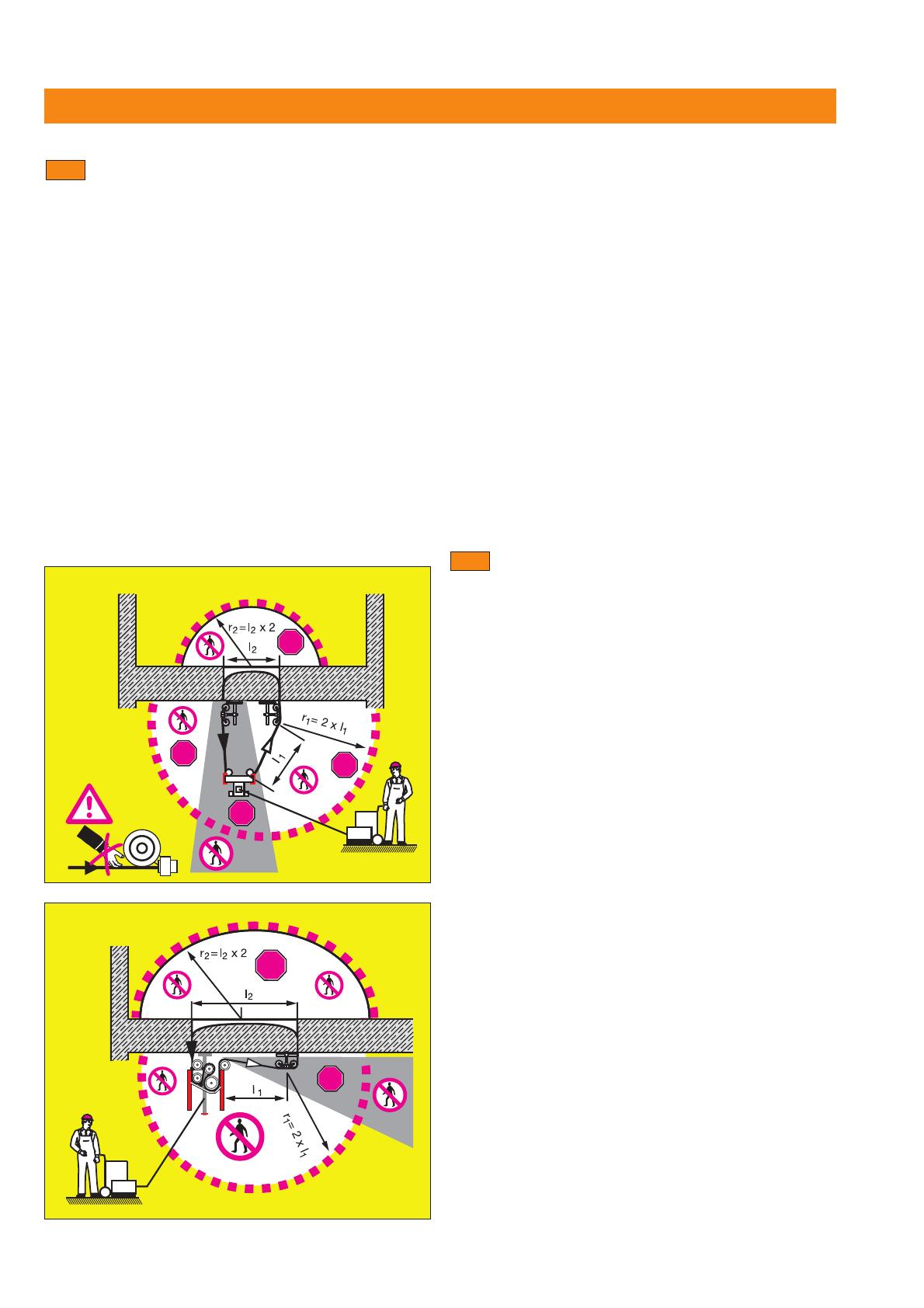
Persons must NEVER enter the danger area while saw-
ing is in progress. The danger area extends to at least
twice the radius of the length of wire that would be
unleashed in the event of the wire breaking and also
includes the area of the extended axis at the wire tension
side. The operator is responsible for cordoning off the
area and restricting access to it.
5.1
STOP
STOP
STOP
STOP
STOP
STOP
Always keep the free wire lengths between the drive
unit and object being cut as short as possible. NEVER
operate the equipment without mounting wire guides on
the construction component to be sawn. In the event of
wire breakage, the wire is thus automatically retained
within the hollow axles of the guide pulleys, thus great-
ly reducing the free length of wire released. Long, free
wire lengths can lead to dangerous wire whiplash in the
event of wire breakage.
When setting up and operating the saw system, always
ensure that no persons are below the area in which you
are working. Falling items of equipment or tools could
lead to serious injury.
Preparations
Sawing work influences the statics of the structure.
Approval must be obtained from the site engineer or
architect prior to carrying out drilling and sawing work.
In cooperation with the site engineer or architect,
ensure that no gas, water, electricity or other supply lines
are located in the cutting area. Supply pipes or cables,
for instance, located close to the cutting area and which
could be damaged by falling objects, must be specially
protected and, if necessary, switched off or temporari-
ly taken out of service.
Ensure that the cooling water used is drained or
extracted in a suitably controlled manner. Water that is
allowed to drain away or spray around in an uncon-
trolled manner can lead to damage or accidents. The
fact that water could drain away into internal, hidden
cavities, e.g. in brickwork or masonry, must also be
taken into account.
Make a careful note of any influence the immediate
surroundings may have on operations. Do not use the
wire saw in areas where there is a risk of explosion or in
close proximity to combustible materials, fluids or gas-
es. Flying sparks or electrostatic discharge can lead to
fires or explosions.
Do not cut materials which, as a result of the cutting
process, may produce toxic or explosive dust or vapors.
5.2
Printed: 07.07.2013 | Doc-Nr: PUB / 5069722 / 000 / 00
  • Page 1 1
  • Page 2 2
  • Page 3 3
  • Page 4 4
  • Page 5 5
  • Page 6 6
  • Page 7 7
  • Page 8 8
  • Page 9 9
  • Page 10 10
  • Page 11 11
  • Page 12 12
  • Page 13 13
  • Page 14 14
  • Page 15 15
  • Page 16 16
  • Page 17 17
  • Page 18 18
  • Page 19 19
  • Page 20 20
  • Page 21 21
  • Page 22 22
  • Page 23 23
  • Page 24 24
  • Page 25 25
  • Page 26 26
  • Page 27 27
  • Page 28 28
  • Page 29 29
  • Page 30 30
  • Page 31 31
  • Page 32 32
  • Page 33 33
  • Page 34 34
  • Page 35 35
  • Page 36 36
  • Page 37 37
  • Page 38 38
  • Page 39 39
  • Page 40 40
  • Page 41 41
  • Page 42 42
  • Page 43 43
  • Page 44 44
  • Page 45 45
  • Page 46 46
  • Page 47 47
  • Page 48 48

Hilti DS WS10 Operating instructions

Type
Operating instructions

Ask a question and I''ll find the answer in the document

Finding information in a document is now easier with AI