Page is loading ...

1
FrameSaverr SLV 9126/9128
1-Slot Unit
Installation Instructions
Document Number 9128-A2-LN12-00
January 2000
Product Documentation Online
Complete documentation for this product is available at http://netcare-esight.com.
Before accessing any information, you must register with NetCare eSight first. Select
Register/Log In. Click on Register. Select Customer (if you have a maintenance
contract) or Warranty (to register your product for warranty coverage). Click Accept to
the Terms and Conditions. Fill out the registration form completely, and then click on
Register. Your registration will be approved within one business day.
When you receive confirmation of your approved registration, log in by clicking on
Register/Log In. Type in your Login ID and Password and click on Submit.
To access the product documentation, select eSight Service Center, then click on
Product Content. Select FrameSaverr SLV, and click on Documentation. Select the
following document:
FrameSaver SLV 9126/9128 User’s Guide (9128-A2-LB20)
To order a paper copy: Within the U.S.A., call 1-800-727-2396; outside the U.S.A.,
call 1-727-530-8623.
Be sure to register your product’s warranty online. Follow the directions on the
enclosed Lucent warranty card.
Package Checklist
Verify that your package contains the following:
-
FrameSaver SLV unit
-
Power cord with desktop power transformer.
— 120 Vac power transformer for a FrameSaver 9128.
— 100–240 Vac power transformer for a FrameSaver 9126.
-
T1 network cable
-
DSX adapter if a FrameSaver 9126 (1 foot – 0.3048 meters)

2
-
ISDN PRI or BRI cable, if applicable
-
FrameSaver SLV 9126/9128 Quick Reference (Document No. 9128-A2-LL10)
Before You Begin
Make sure you have:
-
A dedicated, grounded power outlet that is protected by a circuit breaker within
6 feet of the FrameSaver SLV (service level verifier) unit.
-
A clean, well-lit, and ventilated site that is free from environmental extremes.
-
One-to-two feet of clearance for cable connections.
-
An asynchronous terminal or PC (personal computer).
-
Configuration information for the FrameSaver unit being installed or replaced.
-
Appropriate cables:
— DSX cable
— Data port cables
— COM port-to-terminal or COM port-to-PC cable
— Modem cable
See the User’s Guide for additional information on:
H Troubleshooting
H Cables, Connectors, and Pin Assignments
H Technical Specifications
Cables You May Need to Order
If connecting to a . . . Order a . . .
Model/Feature
Number
T1 line interface/connector
(For use in Canada)
T1 line interface cable,
RJ48C-to-CA81A
3100-F1-510
LAN Customer converter with a DB25
plug on one end and an 8-pin
modular jack on the other end, with
a custom 8-conductor cable and
LAN adapter
3100-F2-910
DSX-1 Cable DSX-1 Adapter Cable
RJ48C-to-DB15
9008-F1-560
Contact your sales representative to order cables.

3
Safety Instructions
Read the Important Safety Instructions and EMI Warnings beginning on page 19.
Installing the Power Supply and Cord
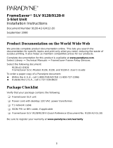
1. Insert the 4-prong plug into the POWER jack.
When inserting the plug at the rear of the FrameSaver unit, align the plug with the
notch above the POWER jack. Make sure the locking tab snaps securely into the
jack.
2.
DSX COM
POWER
MODEM NET DBM
P
O
R
T
2
P
O
R
T
1
POWER
P
O
R
T
1
99-16629
Power Cord /
Transformer
Insert the 3-prong plug
into an ac outlet.
OK
ALM
The front panel
OK LED lights.
2.
3.
3-Prong
Grounded
AC Outlet
Locking
Tab
3.
4. Plug the power cord into the grounded power outlet.
Verification Check:
-
Did any LEDs light?
– If yes, the FrameSaver unit has power.
– If no, refer to Troubleshooting in the User’s Guide.

4
Connecting the COM Port to an Asynchronous Terminal
The FrameSaver unit must first be directly connected to a VT100-compatible
asynchronous terminal or a PC providing VT100 terminal emulation to set up
access and management of the unit.
1. Configure the terminal or PC to be compatible with the FrameSaver unit:
– COM Port in use by your PC: COM1 or COM2.
– COM Port Baud Rate is set to 19.2 kbps.
– Character length is set to 8 data bits.
– Parity is set to none.
– Stop bit is set to 1.
– Flow Control is set to None.
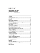
2. Insert the DB25 end of the EIA-232 cable into the FrameSaver unit’s COM port.
DSX COM
POWER
MODEM NET DBM
P
O
R
T
2
P
O
R
T
1
To Connect to a PC
or Async Terminal
COM
Port
99-16628
3. Insert the other end of the cable into the terminal or PC.
4. Tighten the screws on each side of the connector to secure them.
5. Press Enter on the keyboard (or Return, depending upon your keyboard) to display
the Main Menu.
Verification Check:
-
Did the Main Menu appear on the asynchronous terminal?
– If so, continue with the installation.
– If not, recheck terminal and FrameSaver unit compatibility (see settings in
Step 1), or press the Enter key.
Refer to Troubleshooting in the User’s Guide for other possible explanations.

5
A Quick Guide to Configuration
The FrameSaver unit should operate using the default (factory-set) configuration
options, except for the changes specified in these installation instructions. Refer to the
following table for help navigating the menus.
Press the . . . To . . .
Esc key Go back one screen or menu level. To see a visual
representation of the menu levels, see Menu Hierarchy in
the Quick Reference.
Tab key, or
up (↑) and down (↓), or
left (←) and right (→), or
arrow keys
Move the cursor from one menu item to the next.
Enter or Return key Complete the menu or option selection.
Spacebar Display the next available setting when changing a
configuration option. All the available settings for an
option appears at the bottom of the screen.
As an example, follow these steps to go to the Configuration Edit/Display menu so you
can start setting up the unit.
To load a configuration for editing:
1. From the Main Menu, press the down arrow key twice so the cursor is on
Configuration.
2. Press Enter to display the Configuration menu. The Load Configuration From
menu appears.
3. Press Enter to select Current Configuration. The cursor is already on this selection.
The Configuration Edit/Display menu appears.
This sequence of steps would be shown as the menu selection sequence:
Main Menu → Configuration
To save a configuration option change:
1. Press Ctrl-a to switch to the screen function keys area at the bottom of the screen.
2. Type s or S (S
ave) and press Enter. The Save Configuration To menu appears.
3. Press Enter again to save your changes to the Current Configuration.
4. Press Esc until the Configuration Edit/Display menu reappears to continue
configuring the unit.
Press Ctrl-a, type m (M
ainMenu), and press Enter to return to the Main Menu.
The following sections guide you through installation and setup of the FrameSaver unit.

6
The FrameSaver unit is set to automatically configure the following:
H Time Slot Assignment
H Auto-Configuration
It is assumed that the unit is configured for factory default settings at the start of the
installation, and that the automatic configuration features will be used. See Time Slot
Assignment on page 7 and Automatic Configuration on page 9 for information about
these features.
Verifying that Self-Test Passed
To verify that the unit passed its self-test, go to the System and Test Status screen.
Main Menu →Status →System and Test Status
The results of the self-test appears directly under the screen title.
If any failure messages appear, reset the unit by disconnecting, then reconnecting the
power cord. The unit will perform the self-test again. If the failure reappears, call your
service representative for assistance.
Setting the System Clock
1. Select System Information.
Main Menu →Control →System Information
2. Move the cursor to the Date, then the Time field to enter:
– Date in the mm/dd/yyyy format (month/day/year)
– Time in the hh:mm format (hours:minutes)
3. S
ave the settings.
Assigning the Node IP Address
1. Set up the node.
Main Menu → Configuration →Management and Communication →Node IP
2. Minimally, enter the following options:
– Node IP Address
– Node Subnet Mask
3. Save the configuration.

7
Setting Up Physical Interfaces
1. Select each interface’s physical configuration options.
Configuration →Network →Physical
Configuration →Data Ports →Physical
Configuration →DSX-1 (if the DSX-1 interface will be used)
If installing a FrameSaver SLV NAM with an ISDN DBM, postpone configuring the
DBM interface until later.
2. Configure the Network and DSX-1 interfaces to match the network provider’s
settings. Be sure to enable the Interface Status option for these interfaces.
(The network interface is already enabled on a FrameSaver SLV NAM.)
Configure Data Ports to match the DTE’s settings. If Port-2 will be used, enable the
Port Status option for the port.
3. S
ave the configurations.
Setting Frame Relay Characteristics
When installing a FrameSaver SLV NAM, frame relay characteristics must be
configured for the network and data ports.
1. Select the interface’s frame relay configuration options.
Configuration →Network →Frame Relay
Configuration →Data Ports →Frame Relay
2. Configure each interface according to the local management interface (LMI) and
assigned line conditions supplied by the service provider.
3. S
ave the configurations.
Time Slot Assignment
FrameSaver SLV NAM frame relay (network) time slots are discovered automatically
when Time Slot Discovery is enabled (the default setting) on the Frame Relay
Network 1 Assignments screen. This feature can be disabled if you want to manually
configure time slots.
See Assigning Time Slots/Cross Connections in Configuration of the User’s Guide for
additional information about this feature.

8
Setting Up the Modem
The unit has an integral modem for remote management. It is already set up for dial-in
access to the unit, with Port Use set to Terminal.
If using the modem for dialed IP network connectivity (SNMP, Telnet, FTP, or
trap dial-out):
1. Select Modem Port.
Configuration →Management and Communication →Modem Port
2. Minimally, change Port Use to Net Link, and assign the interface’s IP Address and
Subnet Mask if it is different from the Node’s. Change Link Protocol to SLIP, if
necessary (PPP is the default setting).
3. S
ave the configuration.
Setting Up Call Directories if Trap Dial-Out Is Desired
1. Set up directory phone numbers.
Main Menu →Control →Modem Call Directories
2. Select Directory Number A (for Alarm).
3. Enter the phone number(s). Valid characters include:
– ASCII text
– B for blind dialing
– W for wait for dial tone
– P for pulse dialing unless B specified
– T for tone dialing unless B specified
– Space, underscore ( _ ), comma (,) for a 2-second pause, and dash (–)
readability characters
4. S
ave the phone number(s).

9
Setting Up Management
1. Select General SNMP Management.
Configuration → Management and Communication →
General SNMP Management
2. Minimally, set Name 1 Access to Read/Write.
3. S
ave the configuration.
Setting Up Local Management at the Central Site
1. Create a DLCI for the data port.
Configuration →Data Ports →DLCI Records
2. S
ave the configuration.
3. Create a Management PVC using the data port DLCI just created.
Configuration →Management and Communication →Management PVC
Minimally, enter the following options:
– Name for the management PVC
– Interface IP Address and Subnet Mask, if different from the Node’s
– Primary Link for this Management PVC (the user data port)
– Primary DLCI (i.e., the data port DLCI)
4. S
ave the configuration.
Automatic Configuration
The FrameSaver unit provides several automatic configuration features. Frame Relay
Discovery and configuration is one of these features.
Main Menu →Auto-Configuration
The default discovery mode is 1MPort. In this mode, for each DLCI discovered on the
network, a multiplexed network DLCI and a standard data port DLCI will be configured
and connected, and a Management PVC will be embedded in the network DLCI.
NOTE:
When auto-configuration creates a multiplexed DLCI, but a standard DLCI is
needed, change the DLCI to Standard from the network DLCI Records screen:
Configuration →Network →DLCI Records
Other modes can be selected. See Setting Up Automatic Configuration in Configuration
of the User’s Guide for information about other modes and how the Frame Relay
Discovery Mode can be changed.
No automatic configuration occurs until the network cable is connected. If you do not
want management links configured or automatic configuration, change the default
setting for the Frame Relay Discovery feature.

10
Connecting to the Network
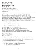
1. Insert the 8-pin connector of the RJ48C network cable into the network interface.
2. Insert the other end of the cable into the RJ48C modular jack.
DSX COM
POWER
MODEM NET DBM
P
O
R
T
2
P
O
R
T
1
99-16630
RJ48C or
RJ48S
Jack
(FrameSaver 9128
Shown)
NOTE:
After connecting the network cable, wait a few minutes to allow
Auto-Configuration a chance to discover the frame relay characteristics
and DLCIs.
Verification Check:
-
Check the Network LEDs. Is the Sig (signal) LED on, and are the OOF (out of
frame), and ALM (alarm) LEDs off? If so, the network interface is set up correctly
and is operational. If not, make sure both ends of the network cable are properly
seated and secured.
-
Verify that the network physical options are configured correctly.
Main Menu → Configuration →Network →Physical
-
Check Health and Status messages in the left column of the System and Test
Status screen to see the LMI status, to verify that LMI is up.
Main Menu → Status → System and Test Status
If LMI Down, Net1-FR1 appears for more than three minutes, or any other
network-related status message appears, refer to the status information in
Operation and Maintenance of the User’s Guide for possible reasons for the
messages and what can be done to resolve the problem.
If the unit does not have ISDN backup capability, proceed to Configuring SNMP Trap
Managers and Trap Dial-Out on page 13.

11
Setting Up the ISDN DBM
FrameSaver 9128 units may be equipped with an ISDN PRI or BRI DBM. These
instructions are for units with ISDN backup capability.
The following guidelines apply:
H Central site configuration guidelines:
– Set up the ISDN DBM physical interface.
– If a BRI DBM, change the Automatic Backup Configuration to
Multi_Site_Backup. (A PRI DBM is already configured for multisite backup.)
– Modify the Link Profile(s) that Automatic Backup Configuration created to add a
phone number.
– Configure the unit to answer calls from the remote sites. (A PRI DBM is already
configured to answer calls.)
H Remote site configuration guidelines:
– Set up the ISDN DBM physical interface.
– If a PRI DBM, change the Automatic Backup Configuration to
Single_Site_Backup. (A BRI DBM is already configured for single-site backup.)
– Modify the HQ_Site Link Profile that Automatic Backup Configuration created to
add a phone number.
– Configure the remote unit to originate calls to the central site. (A BRI DBM is
already configured to originate calls.)
– Set the criteria by which automatic backup will take place.
Setting Up the DBM Physical Interface
1. Configure the DBM interface.
Main Menu →Configuration →ISDN →Physical
2. Minimally, set the following configuration options:
– Interface Status is set to Enable.
– Originate or Answer is set to Answer for a central site unit, and set to Originate
for a remote site unit.
– Local Phone Number 1 is entered, plus the following:
FrameSaver Unit with BRI FrameSaver Unit with PRI
Configure the B-channels:
H Service Profile ID1 (SPID)
H Local Phone Number 1
H Service Profile ID2 (SPID)
H Local Phone Number 2
Configure T1 physical characteristics
to match the service provider’s
settings.
H Local Phone Number
3. Save the configuration and return to the ISDN menu.

12
Setting Up Automatic Backup Configuration
The Automatic Backup Configuration feature is used to automatically create alternate
DLCI records and PVC connections on the ISDN DBM (backup) interface.
This feature is already set up in FrameSaver units with a DBM.
H Single_Site_Backup is the default for a BRI DBM.
H Multi_Site_Backup is the default for a PRI DBM.
See the User’s Guide for additional information.
Modifying ISDN Link Profiles
1. Select Link Profiles, then Modify.
2. Add a name and phone number to the ISDN Link Profile(s) created by Automatic
Backup Configuration.
– Name for the destination entered (e.g., Tampa). The default setting of HQ_Site.
– Link Status is set to Auto.
– Phone numbers entered:
Originating Unit Answering Unit
Outbound phone number.
Valid characters include:
H Numbers (0–9)
H Special characters * and #
H Spaces
H Parentheses ( )
Inbound Calling ID1 and ID2. These
are the phone numbers of units from
which calls will be accepted.
Valid characters include:
H Numbers (0–9)
NOTE:
Remember to include local dial-out numbers (i.e., 9, then the number).
– Maximum Link Rate is changed, if necessary. The default setting is 64 kbps.
3. S
ave the configuration.
Setting the Criteria for Automatic Backup
1. Enable Auto Backup.
Main Menu →Configuration →Auto Backup Criteria
When a failure occurs, the unit automatically enables the Alternate Link and traffic
is rerouted over the backup (alternate) interface.
2. Specify When Auto Backup Allowed – Always or Restrict. If Restrict is selected,
specify the days and hours of the week during which automatic backup can take
place.
3. S
ave the configuration.

13
Setting Up Service Provider Connectivity
at the Central Site
When management needs to be set up between a service provider’s customer and its
network operations center (NOC), a non-multiplexed DLCI must be configured to carry
management data between the customer’s central site and the NOC console. This
requires that a frame relay discovered DLCI needs to be modified. This is because all
auto-configured network DLCIs are configured as multiplexed DLCIs.
To set up NOC management:
1. Select DLCI Records on the network interface:
Configuration →Network →DLCI Records
2. Select Mo
dify. The Modify DLCI Record for DLCI Number prompt appears.
3. Select the DLCI that will be used by pressing the spacebar until the correct DLCI
number appears, then select it.
4. Change the DLCI Type from Multiplexed to Standard.
The DLCI in connections. Update DLCI usage as follows: prompt
appears.
5. Select the Delete EDLCI Connections and Make a Mgmt Only PVC
option.
PVC connections for the selected DLCI are broken, the Port-1 DLCI mapped to
this network DLCI and the embedded management DLCI (EDLCI) are deleted, and
the selected DLCI will be reconfigured as a management PVC using the Node IP
Address.
Configuring SNMP Trap Managers and Trap Dial-Out
Once the FrameSaver unit is connected to the network, SNMP trap managers, SNMP
traps, and trap dial-out can be configured.
1. Select SNMP Traps.
Main Menu →Configuration →Management and Communication →
SNMP Traps
2. Configure the following:
– Enable SNMP Traps.
– Identify the total Number of Trap Managers.
– Specify the IP address of the NMS(s) to which traps will be sent.
– Specify the network Destination for the Trap Manager(s).
– Select desired trap categories.
– Enable Trap Dial-Out, if desired.
3. S
ave the configuration.
4. Return to the Main Menu.

14
Verifying the End-to-End Path
After installation of a remote site unit, run an IP Ping test to Ping the NMS at the central
site and verify that the entire path from the remote unit to the NMS is functioning. To run
the IP Ping test, NMS trap managers must have been configured for the remote unit.
One of those trap managers must be the central site NMS.
1. Select the IP Ping test.
Main Menu →Test →IP Ping
2. Enter the IP Address of the device being Pinged, then select Start.
NOTE:
When running tests, the cursor is positioned over the Start command. Press
Enter to start the test. Stop is displayed while the test is running. Press Enter
again to issue the Stop command.
– While the test is running, In Progress... is displayed in the Status field.
– When the test is finished, Alive. Latency = nn ms should appear as the
Status (nn being the amount of time the test took in milliseconds).
If any other message is displayed, additional testing will be required. See Device
Messages in Operation and Maintenance of the User’s Guide for information
about IP Ping-related messages.
Connecting to the DSX
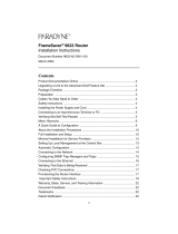
1. Connect the 8-positon modular plug end of the DSX cable to the DSX-1 interface.
If your DSX cable has a DB15 end, use a DSX-1 adapter cable.
Refer to the pin assignment information in the User’s Guide to ensure you have
proper connections.
2. Connect the other end of the cable to the CPE (customer premises equipment,
like a PBX).
3. Tighten the screws on each side of the connector to secure them.
DSX COM
POWER
MODEM NET DBM
P
O
R
T
2
P
O
R
T
1
99-16631
PBX

15
Verification Check:
-
Check the DSX LEDs. Is the Sig (DSX-1 signal) LED on, and are the DSX-1 OOF
(out of frame) and ALM (alarm) LEDs off?
– If so, the DSX interface is set up correctly and ready to communicate.
– If no, check that both ends of the DSX cable are properly seated and secured.
When OOF is on, match the Line Framing Format and Line Coding Format
options to the network provider’s settings.
When ALM is on, contact the service provider.
-
Check Health and Status messages in the left column of the System and Test
Status screen to verify that there are no DSX-1 Health and Status messages.
Main Menu →Status →System and Test Status
If any DSX-1 messages appear, refer to the status information in Operation and
Maintenance of the User’s Guide.
In the User’s Guide, see Operation and Maintenance for additional status information,
and Troubleshooting for additional troubleshooting information.
Connecting to the DTE
1. Connect one end of the DTE’s V.35 cable to the data port.
2. Plug the other end of the cable into the DTE.
3. Tighten the screws on each side of the connector to secure them.
DSX COM
POWER
MODEM NET DBM
P
O
R
T
2
P
O
R
T
1
99-16632
RJ48C
Jack
If installing a FrameSaver 9128, repeat this procedure for the second port.
Verification Check:
-
Check that the port OK LED is on?
– If so, the port is ready to communicate.
– If not, check that both ends of the V.35 cable are properly seated and secured.
Then, check the DTE; RTS or DTR could be down on the DTE.

16
-
Check Health and Status messages in the left column of the System and Test
Status screen for messages.
Main Menu → Status → System and Test Status
– If System Operational appears, the Port-1 interface is set up correctly and
is operational.
– If System Operational does not appear, refer to the status information in
Operation and Maintenance of the User’s Guide.
NOTE:
When any error conditions are detected, a status message will appear at the
bottom right corner of the screen.
Connecting the Modem
1. Insert the RJ11C connector on the modem cable into the Modem/MDM interface.
2. Insert the other end of the cable into the phone service RJ11C jack.
DSX COM
POWER
MODEM NET DBM
P
O
R
T
2
P
O
R
T
1
98-16235
RJ11C
Jack
(FrameSaver 9128
Shown)
Verification Check:
If Port Use is set to Terminal (dial-in access):
-
Dial the modem’s phone number using a remote asynchronous terminal or PC.
-
Verify that the Main Menu appears.
If Port Use is set to Net Link (SNMP, Telnet, FTP, and trap dial-out):
-
Dial the modem’s phone number using a PC running PPP or SLIP link protocol.
-
From the PC, run an IP Ping test to the modem interface.
If your results using either method are unsuccessful, make sure both ends of the
modem cable are properly seated and secured. Then, verify that the modem was
configured correctly (see Setting Up the Modem on page 8). Otherwise, refer to the
status information in Operation and Maintenance of the User’s Guide.
Proceed to Connecting to the ISDN on page 17 if the FrameSaver unit is equipped with
a DBM.

17
Connecting to the ISDN
This procedure only applies to a FrameSaver unit equipped with an ISDN DBM.
1. Insert the 8-pin connector on the ISDN cable into the DBM interface.
2. Insert the other end of the cable into the ISDN service jack.
– RJ49C for a FrameSaver unit with BRI DBM.
– RJ48C for a FrameSaver unit with PRI DBM.
3. Setup the unit at the other end of the ISDN circuit.
DSX COM
POWER
MODEM NET DBM
P
O
R
T
2
P
O
R
T
1
98-16236
RJ49C or
RJ48C
Jack
(FrameSaver 9128
Shown)
Verification Check:
-
Verify the ISDN lines by checking the DBM Interface Status.
Main Menu →Status →DBM Interface Status
Line Status should be Active. If an invalid (Inv) status (e.g., Inv SPID for a BRI
DBM) is displayed, verify that you entered ISDN physical options correctly.
-
Check backup setup and that data can be passed between DBMs.
– Select Test, then ISDN Call/PVC Tests
Main Menu →Test →ISDN Call/PVC Tests
– Select the link to be tested.
– Start a Test Call. The Status should be Active.
– Wait as the originating DBM places the backup call.
The originating unit’s Test LED is on.
If the Result is . . . Then . . .
Frame Relay Link Up The call was successful.
Frame Relay Link
Suboptimal
Not all links have come up. Verify that the
Maximum Link Rate (Kbps) setting in the ISDN
Link Profile is the same at both ends.
Frame Relay Link Down The call was unsuccessful. Verify the configuration
and Link Status in the ISDN Link Profile.
– Select Stop to end the Test Call.
See Verifying Backup Setup in Configuration of the User’s Guide for additional
information.

18
Check PVC Connections
Check PVC connections to verify that all PVCs, including management PVCs, are
configured, and to see whether the PVC is active or not.
1. Press Esc to return to the Status menu.
2. Select PVC Connection Status.
The PVC Connection Status screen shows all PVC connections; the interface and
DLCI number of the source interface and DLCI number for the destination
interface. You can also see whether the PVC is active.
3. Verify that each PVC is active.
– If active, the FrameSaver unit should be passing data.
– If not active, no data traffic can be carried by the PVC. If the PVC is configured
correctly, the circuit may be down.
In the User’s Guide, see Operation and Maintenance for additional status information,
and Troubleshooting for additional troubleshooting information.
Check That Data is Being Received
1. Return to the Main Menu, then select Status.
2. Select Performance Statistics, and select an interface’s frame relay statistics
(e.g., Network Frame Relay).
Main Menu →Status →Performance Statistics →Network Frame Relay
3. Clear the statistics and see whether the counts for Frames Received and
Characters Received under the Frame Relay Link are incrementing, and verify that
there are no errors under the Frame Relay LMI statistics. R
efresh the screen to
update the counts.
– If data is being received, the count increments after refreshing the screen.
– If data is not being received, recheck the cable connections, and replace or
repair a damaged cable. Recheck LMI status; you may need to contact your
service provider. Next, check the DLCI’s status.

19
!
Important Safety Instructions
1. Read and follow all warning notices and instructions marked on the product or
included in the manual.
2. This product is intended to be used with a 3-wire grounding type plug – a plug
which has a grounding pin. This is a safety feature. Equipment grounding is vital to
ensure safe operation. Do not defeat the purpose of the grounding type plug by
modifying the plug or using an adapter.
Prior to installation, use an outlet tester or a voltmeter to check the ac receptacle
for the presence of earth ground. If the receptacle is not properly grounded, the
installation must not continue until a qualified electrician has corrected the
problem.
If a 3-wire grounding type power source is not available, consult a qualified
electrician to determine another method of grounding the equipment.
3. Slots and openings in the cabinet are provided for ventilation. To ensure reliable
operation of the product and to protect it from overheating, these slots and
openings must not be blocked or covered.
4. Do not allow anything to rest on the power cord and do not locate the product
where persons will walk on the power cord.
5. Do not attempt to service this product yourself, as opening or removing covers
may expose you to dangerous high voltage points or other risks. Refer all servicing
to qualified service personnel.
6. General purpose cables are provided with this product. Special cables, which may
be required by the regulatory inspection authority for the installation site, are the
responsibility of the customer.
7. When installed in the final configuration, the product must comply with the
applicable Safety Standards and regulatory requirements of the country in which it
is installed. If necessary, consult with the appropriate regulatory agencies and
inspection authorities to ensure compliance.
8. A rare phenomenon can create a voltage potential between the earth grounds of
two or more buildings. If products installed in separate buildings are
interconnected, the voltage potential may cause a hazardous condition. Consult a
qualified electrical consultant to determine whether or not this phenomenon exists
and, if necessary, implement corrective action prior to interconnecting the products.

20
9. In addition, if the equipment is to be used with telecommunications circuits, take
the following precautions:
— Never install telephone wiring during a lightning storm.
— Never install telephone jacks in wet locations unless the jack is specifically
designed for wet locations.
— Never touch uninsulated telephone wires or terminals unless the telephone
line has been disconnected at the network interface.
— Use caution when installing or modifying telephone lines.
— Avoid using a telephone (other than a cordless type) during an electrical
storm. There may be a remote risk of electric shock from lightning.
— Do not use the telephone to report a gas leak in the vicinity of the leak.
EMI Warnings
!
WARNING:
This equipment has been tested and found to comply with the limits for a
Class A digital device, pursuant to Part 15 of the FCC rules. These limits are
designed to provide reasonable protection against harmful interference
when the equipment is operated in a commercial environment. This
equipment generates, uses, and can radiate radio frequency energy and, if
not installed and used in accordance with the instruction manual, may cause
harmful interference to radio communications. Operation of this equipment
in a residential area is likely to cause harmful interference, in which case, the
user will be required to correct the interference at his own expense.
The authority to operate this equipment is conditioned by the requirements
that no modifications will be made to the equipment unless the changes or
modifications are expressly approved by the manufacturer.
In order to maintain compliance with FCC limits, any supplied ferrite chokes
must be installed in accordance with the card installation instructions.
!
WARNING:
To Users of Digital Apparatus in Canada:
This Class A digital apparatus meets all requirements of the Canadian
interference-causing equipment regulations.
Cet appareil numérique de la classe A respecte toutes les exigences du
règlement sur le matériel brouilleur du Canada.
/