
2630 Airport Road · Kinston, NC 28504
Phone: 252-522-3031· Fax: 252-522-0214
www.fieldcontrols.com
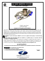
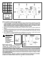
OIL VENT DAMPER SYSTEM
Model: OVD - 4 through 8
Field Controls (OVD) oil vent damper reduces off cycle losses through oil fired heating appliances. When the
appliance is in a standby mode, heat escapes up the chimney. The heat comes from the appliance and the
conditioned space. To significantly reduce these losses, install a Field Controls Oil Vent Damper. The damper is
installed in the vent system between the draft control and chimney. The WMO-1 blocked vent safety shut off
installs between the draft control and appliance. When properly installed, the damper opens before the burner fires
and closes after the burner shuts off.
WARNING: The Oil Vent Damper CANNOT be used on an appliance that employs a constant burning
pilot.
The Field Controls Oil Vent Damper MUST be installed by a qualified agency in accordance with the
manufacturer’s installation instructions.
The definition of a qualified agency is: any individual, firm, corporation or company which either in person or
through a representative is engaged in, and is responsible for, the installation and operation of oil appliances, who
is experienced in such work, familiar with all the precautions required, and has complied with the requirements of
the authority having jurisdiction. The oil vent damper is designed to service one appliance only.
DO NOT DESTROY
AFTER INSTALLATION, THESE INSTRUCTIONS MUST REMAIN WITH THE EQUIPMENT FOR SERVICE OF THE APPLIANCE.
Items Included: 1) Oil Vent Damper Assembly
1) WMO-1 with gasket
1) Wiring Harness
Listed to UL-17 Standard and CSA B140.14
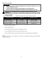
CAUTION
Before installing the oil vent damper system:
1. Read this manual carefully and completely.
2. Be sure to follow all procedures and safety inspections.
3. Do not over ride the action of any safety or operational controls.
Tape Plug
Here

2
FEATURES
1. Service Switch – Holds damper open and allows the appliance to operate without the damper operating.
2. 18 month limited warranty on motorized assembly from manufactured date.
3. Two internal safety switches
4. Power open, power close – extends product life. Reduced electrical consumption
5. Metal shielded cable wire harness.
6. WMO-1 Blocked Vent Safety Shut Off
7. Flex Seal provides self cleaning action
8. Stainless steel pipe assembly.
OPERATION
When the oil heating appliance receives a call for heat, the damper rotates to the open position before the burner circuit is
energized. If the damper does not rotate to the open position, the burner circuit will not be energized and will not allow the
burner to fire. When the call for heat is satisfied the damper will remain open for approximately 3 minutes to allow the residual
flue gases to escape before closing. When properly installed, the electrical circuits in this product are designed not to override
the existing limit and safety controls of the appliance.
TO THE USER
For continued safe operation, the heating appliance should be inspected annually by a qualified service agency. It is
recommended that the homeowner should have the vent system and the damper device examined annually for deterioration
from corrosion or other sources. This inspection should be performed prior to each heating season.
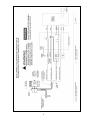
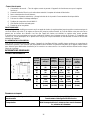
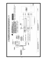
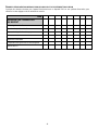
GENERAL INFORMATION
DIMENSIONAL DATA
ELECTRICAL DATA
Burner and Transformer Electrical Rating
Burner motors rated up to 1/6 hp, 5.8 Amps
Ignition Transformer rated at 250 VA or less
Timing
5 sec, Power open
Approximately 3 minute time delay to close
5 sec, Power close
Figure 1
Dim ‘A’
Pipe
Size
in inches
Dim ‘B’
Length
in inches
Dim ‘C’
Total
Height
in inches
Dim ‘D’
in inches
Dim ‘E’
in inches
Pipe
removal
dimension
in inches
4
(102mm)
6
(152mm)
10-1/16
(256mm)
15/16
(24mm)
5
(127mm)
3-1/2
(89mm)
5
(127mm)
6 (
152mm)
11-1/16
(281mm)
15/16
(24mm)
5
(127mm)
3-1/2
(89mm)
6
(152mm)
6-1/2
(165mm)
12-1/16
(306mm)
1-1/8
(29mm)
5-1/2
(140mm)
4
(102mm)
7
(178mm)
7-1/16
(179mm)
13-1/16
(332mm)
1-3/8
(35mm)
6-1/16
(154mm)
4-9/16
(116mm)
8
(203mm)
8-1/16
(205mm)
14-1/16
(357mm)
1-7/8
(48mm)
7-1/16
(179mm)
5-9/16
(141mm)

3
PRE-INSTALLATION WARNINGS
1. The Field Controls Oil Vent Damper must be installed by a qualified agency in accordance with the
manufacturer’s installation instructions. The definition of a qualified agency is: any individual, firm, corporation
or company which either in person or through a representative is engaged in, and is responsible for, the
installation and operation of oil burning appliances, is experienced in such work, familiar with all the precautions
required, and has complied with all the requirements of the authority having jurisdiction. The oil vent damper is
designed to service one appliance only.
2. The qualified agency shall fill in the agencies name, address and installation date on the label attached to the
vent damper device.
3. The Field Controls automatic oil vent damper can only be installed on automatically operated oil appliances that
utilize atomizing power oil burners.
4. The Field Controls automatic oil vent damper must not be installed on oil appliances utilizing a direct vent
system, sealed combustion system or vaporizing type burners.
5. Do not override the action of any existing safety or operational controls.
6. When servicing controls, all wires must be LABELED prior to disconnection. Wiring errors can cause improper
and dangerous operation.
7. Device must be installed by a qualified agency, in accordance with the following standards:
In the US
NFPA 31 Standard for the Installation of Oil -Burning Equipment
NFPA 211 Standard for Chimneys, Fireplaces, Vents and Solid Fuel Burning Appliances
NFPA 70 National Electric Code
In Canada
CSA B139 Installation Code for Oil Burning Equipment
C22.1 Canadian Electrical Code Part 1
8. The maximum temperature of the selected location must not exceed 1000 degrees F (538°C) Measure the flue
gas temperature at the appliance flue collar.
9. Install downstream from the appliance draft control, as close to the draft control as practical, and without
modification to the draft control or the vent damper unit.
10. Locate the WMO-1 between the draft control and the flue collar of the single appliance for which it services.
11. Locate damper in a venting system or section of a venting system so that it services only the single appliance
for which it is intended.
12. A minimum clearance of 18 inches (457 mm) between the damper device and combustible construction must be
maintained and that there be provisions for access and service of the damper device.
13. Position indicator and service switch must be accessible to the user.
14. This device must be installed only on a oil appliance connected to a factory built chimney or vent system
complying with a recognized standards, or a masonry or concrete chimney lined with a lining material
acceptable to the authority having jurisdiction.
PRE- INSTALLATION INSPECTIONS
PROCEDURE FOR SAFETY INSPECTION OF AN EXISTING APPLIANCE INSTALLATION
The following procedure is intended as a guide to aid in determining that an appliance is properly installed and is in a
safe condition for continuing use.
This procedure is predicated on central furnace, boiler and water heater installations, and it should be recognized
that generalized procedures cannot anticipate all situations. Accordingly, in some cases deviation from this
procedure may be necessary to determine safe operation of the equipment.
1. This procedure shall be performed prior to installation of the automatic vent damper system.
2. If it is determined there is a condition which could result in unsafe operation, the appliance should be shut
off and the owner advised of the unsafe condition. Do not install the automatic vent damper system until the
unsafe condition has been corrected.

4
SAFETY INSPECTION
1. Conduct a visual leakage test of the oil appliance piping and control system downstream of the oil shutoff valve
in the supply line to the appliance.
2. Visually inspect the venting system for proper size, horizontal pitch and vent termination, and determine there is
no blockage or restriction, leakage, corrosion and other deficiencies which could cause an unsafe condition.
3. Determine that the chimney or vent is acceptable to the authority having jurisdiction.
4. Inspect burner, combustion chamber and flue passages for blockage and corrosion.
5. Applicable only to furnaces – inspect heat exchanger for cracks, openings or excessive corrosion.
6. Applicable only to water heaters and boilers – inspect for evidence of water or combustion product leaks.
7. Insofar as is practical, close all building doors and windows and all doors between the space in which the
appliance is located and other spaces of the building. Turn on clothes dryers, stove top barbecues and central
vacuum cleaners. Turn on any exhaust fans, such as range hoods and bathroom exhausts, so they will operate
at maximum speed. Do not operate a summer exhaust fan. Close fireplace dampers. If, after completing Steps 9
through 12, it is believed sufficient combustion air is not available, refer to local codes or in the absence of local
codes, in the United States NFPA 31- Standard for the Installation of Oil Burning Equipment; NFPA 211- Standard
for Chimneys, Fireplaces, Vents and Solid- Fuel Burning Appliances for guidance. In Canada CSA B139
Installation Code for Oil Burning Equipment.
8. Place in operation the appliance being inspected. Follow the appliance manufacturer’s startup instructions.
Adjust the thermostat so appliance will operate continuously.
9. Adjust the air and head settings according to the burner appliance manufacturer instructions. Determine that
the burner is operating properly, by carbon dioxide concentration, flue gas temperature and smoke density tests.
Check the cadmium sulfide cell to determine it is operating properly.
10. Turn on all other fuel-burning appliances within the same room so they will operate at their full inputs. Follow
start up instructions for each appliance.
11. Test for spillage at the draft control opening after 5 minutes of main burner operation. Use a match, candle or
smoke from a cigarette. Vent connected power atomizing oil burning equipment shall be operated for several
minutes and checked to see that the combustion products are going up the chimney, or vent. Take a draft
reading to assure the system over fire draft is according to the burner and appliance manufacturer instructions.
If the chimney or vent is drawing properly a negative pressure will be in the vent system. If not, the combustion
products will tend to be drawn out of the draft control. If the combustion products are escaping from the
opening of the draft control, the equipment should not be operated until proper adjustments or repairs are made
to provide adequate combustion air or draft through the chimney or vent system.
12. Repeat Step 11 on all other fuel burning appliances.
13. Return doors, windows, exhaust fans, fireplace dampers and any other fuel burning appliances to their previous
conditions of use.
14. Applicable only to furnaces – Check both the limit control and the fan control for proper operation. Follow the
appliance control manufacturer instructions for checking the fan and limit controls.
15. Applicable only to boilers –
a. Determine that the water pumps are in operating condition.
b. Test low water cutoffs, automatic feed controls, and relief valves in accordance with the manufacturer’s
recommendations to determine they are in operating condition.
16. Applicable only to water heaters – Test relief valve, combination aquastat and high limit control in accordance
with the manufacturer’s recommendations to determine they are in operating condition.
UNPACKING INSTRUCTIONS
1. The Field Controls OVD Series Oil Vent Damper is packaged in a single carton. It contains an assembled OVD, a
prewired WMO-1 safety switch with fiber gasket and attached metal shielded cable wire harness, instruction
manual and a vent plug.
2. Remove assembly and examine each component for possible damage.
3. If damage is apparent do not install the oil vent damper system.

5
INSTALLATION OF THE UNIT
WARNING: Install the oil vent damper system to service only the single appliance for
which it is intended. If improperly installed a hazardous condition such as an explosion
or carbon monoxide poisoning or death could result.
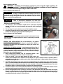
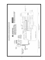
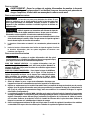
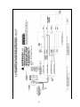
INSTALLATION OF THE VENT PLUG
1. The vent plug is to be installed for a tight seal. To avoid motor assembly
damage, be careful not to turn the damper gate manually, while installing the
vent plug.
2. The vent plug is located on the front cover of this installation manual.
3. Insert the vent plug into the hole in the damper gate. To secure the vent plug,
bend the four tabs on the vent plug outward (See Figure 2).
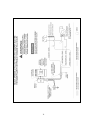
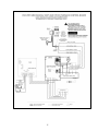
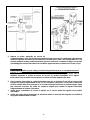
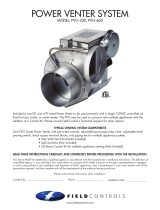
INSTALLATION OF THE VENT DAMPER
VERTICAL PIPE INSTALLATIONS: The oil vent damper is not position
sensitive. You may mount the vent damper in any position. Maintain a
minimum of 18 inches (457 mm) between the damper pipe surface and
combustible material.
HORIZONTAL PIPE INSTALLATIONS: To avoid premature failure of the oil
vent damper refer to Figure 3. Avoid mounting the damper directly above
or below the vent pipe. We suggest 1:00 to 5:00 or 7:00 to 11:00 ‘o clock
positions. Maintain a minimum of 18 inches (457 mm) between the damper
pipe surface and combustible material.
1. Before starting the installation, turn off all electrical power to the
appliance at the appliance service switch or circuit breaker.`
2. Locate a position in the vent pipe between the draft control and
chimney for the damper device. Install the oil vent damper, as close to the draft control as practical (within a
minimum of two inches from the draft control collar), without modification of either the draft control or the vent
damper device. (Layout A)
3. The WMO-1 Blocked Vent safety shut off must be installed between the appliance flue collar and draft control.
(NOTE: The metal shielded cable wire harness from the WMO-1 safety switch and vent damper is only 24 inches
(609 mm)). (Layout A) Wire harness plugs into motor assembly. Push and lock keyed wire harness into motor
assembly receptacle. Push and lock metal y-connector into strain relief bracket.
4. A minimum clearance of 18 inches (459 mm) between the vent damper pipe and combustible material must be
maintained and there must be provisions for access to service the oil vent damper system.
5. Remove the appropriate section of vent pipe connector on the downstream side of the draft control and shorten
the pipe to make clearance for the vent damper pipe (See Table 1 for proper dimensions and Layout B). If
needed, crimp the end of the vent pipe near the outlet of the draft control. The vent pipe and vent damper pipe
assembly joints should overlap 1¼ Inches (32 mm).
Figure 3
CAUTION
The vent damper system must be located only in the vent
pipe that services a single appliance for which it is electrically connected
and controlled.
CAUTION
The plug is installed for minimum leakage. If an odor or
nozzle after drip occurs, the plug may be removed to allow minimal
ventilation through the appliance burner. The ventilation helps to cool the
burner nozzle in the standby mode.
CAUTION
Failure to follow these instructions can cause odor
problems and minor property damage. Do not install the vent plug on systems
with a brick combustion chamber.
Figure 2

6
CAUTION
Make sure not to egg shape the pipe assembly when installing, it can create binding
of the damper gate and cause premature motor failure and nuisance calls. Install the vent damper with
the directional arrow and crimped end of the vent damper pipe pointed toward the chimney. Reinstall
the shortened length of vent pipe connector and vent damper. Position the motor assembly according
to the position limitation listed above.
6. Secure the oil vent damper to the vent pipe with 1/2 inch (13mm) sheet metal screws or pop rivets. The spacing
should be equally spaced 120° apart around the circumference. Three fasters shall be used at the inlet and outlet
of the pipe assembly. Be careful not to allow the fasteners to obstruct the vent damper gate. It may be necessary
to provide suitable pipe hangers to support the oil vent damper independent of the venting system.
7. Check the damper service switch on the side of the damper motor assembly and it’s in the automatic position.
8. Check to see the flat shaft is fitted into the motorized assembly. The flat shaft must have a factory installed
washer and cotter pin.
Layout B
Layout A

7
Dim ‘A’
Pipe Size
in inches
Pipe removal
dimension
in inches
4
(102mm)
3-1/2
(89mm)
5
(127mm)
3-1/2
(89mm)
6
(152mm)
4
(102mm)
7
(178mm)
4-9/16
(116mm)
8
(203mm)
5-9/16
(141mm)
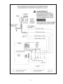
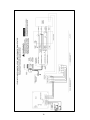
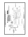
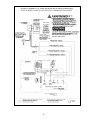
INSTALLATION OF THE WMO-1 BLOCKED VENT SAFETY SHUT OFF
1. The WMO-1 Blocked Vent safety shut off must be installed between the appliance flue collar and draft control.
(NOTE: The metal shielded cable wire harness from the WMO-1 safety switch and vent damper is only 24 inches
(609 mm)). Wire harness plugs into motor assembly. Push and lock keyed wire harness into motor assembly
receptacle. (See Keyway Diagram) Push and lock metal y-connector into strain relief bracket.
2. Drill or pierce a 3/4” diameter hole in the vent pipe near the appliance outlet. (See Figure 4)
3. The heat transfer tube must have the fiber gasket installed against the mounting plate before attaching the unit
to the vent pipe. Insert the heat transfer tube with gasket into the 3/4” diameter hole.
4. Secure the assembly to the vent pipe with a minimum of 4 sheet metal screws. The channel must be mounted
horizontally, unless specified differently by the appliance manufacturer. (See Figure 4)
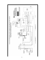
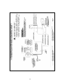
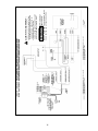
WIRING INSTRUCTIONS
Wire the vent damper and controls in accordance with the National Electrical Code, manufacturer's
recommendations and/or applicable local codes. THE UNIT MUST BE GROUNDED. Check ground circuit to make
certain that the unit has been properly grounded. The wiring should be protected by an over current circuit device
rated at 15 amperes. Caution must be taken to ensure that the wiring does not come into contact with any heat
source. All line voltage and safety control circuits, between the vent damper and the appliance, MUST be wired in
accordance with the National Electrical Code for Class I wiring or equivalent methods.
BEFORE STARTING WIRING, TURN OFF ALL ELECTRICAL POWER TO THE APPLIANCE AT THE
APPLIANCE SERVICE SWITCH OR CIRCUIT BREAKER!!
Layout C
WARNING:
Switch connection
channel must be
mounted
horizontally, unless
specified differently
by the appliance
manufacturer.
Figure 4
Keyway Diagram

8

9

10

11

12

13

14

15

16

17

18

19
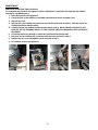
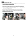
MAINTENANCE
WMO-1 BLOCKED VENT SAFETY SHUT OFF
For continued safe operation, the appliance-switch combination is required to be inspected and maintain
annually by a qualified agency.
1. Disconnect power to the appliance.
2. Loosen the two screws holding on the WMO-1 blocked vent switch assembly cover.
3. Remove the cover.
4. Remove the screw holding the control box to the heat transfer tube assembly. Slide the control box
off the heat transfer tube assembly.
5. Carefully remove any buildup from the thermal switch surface. DO NOT DENT OR SCRATCH THE
SURFACE OF THE THERMAL SWITCH. IF THE THERMAL SWITCH IS DAMAGED, REPLACEMENT IS
REQUIRED.
6. Check and remove any buildup or obstruction inside the heat transfer tube.
7. Remount, lock and refasten the control box with the screw removed in step 4.
8. Reattach the box cover and tighten screws loosened in step 2.
9. Re-establish power to the appliance.
Step 1
Step 2
Step 3
Step 4

20
PROBLEM SOLUTION GUIDE
WARNING: Do not negate the action of any existing safety or operational controls
Voltage readings are 120 VAC. Voltage readings are taken at the wire harness attached
where it attaches to the appliance. Make sure the vent damper service switch is in the
automatic position.
Normal Voltage Readings Note: Black, Orange & Yellow must be the same polarity
White # 4 120 VAC Neutral
BLACK # 1 120 VAC HOT
ORANGE # 2 120 VAC SIGNAL IN TELLS VENT DAMPER TO OPEN
YELLOW # 3 120 VAC SIGNAL OUT ONCE VENT DAMPER IS OPEN
REMOVE 120 VAC SIGNAL FROM ORANGE # 3. DAMPER CLOSES IN APPROXIMATELY 3 MINUTES
NOTE: The first cycle to close may take up to 12 minutes. The capacitors must fully charge. Before Normal
closure times will occur.
CAUTION
When servicing controls, all wires must be labeled prior to disconnection. Wiring errors can cause
improper and dangerous operation.
Do not turn damper open manually or motor damage will occur and Void the Warranty.
DO NOT CUT PLUG OFF OF DAMPER MOTOR ASSEMBLY OR THE WARRANTY WILL BE VOID.
120 VAC POWER
Power On
Damper Position
White # 4 & Black #1
All Times
Open or Closed
White # 4 & Orange # 2
Calling for Heat
Open or Opening
White # 4 & Yellow # 3
During Combustion
Damper Open
Page is loading ...
Page is loading ...
Page is loading ...
Page is loading ...
Page is loading ...
Page is loading ...
Page is loading ...
Page is loading ...
Page is loading ...
Page is loading ...
Page is loading ...
Page is loading ...
Page is loading ...
Page is loading ...
Page is loading ...
Page is loading ...
Page is loading ...
Page is loading ...
Page is loading ...
Page is loading ...
Page is loading ...
Page is loading ...
Page is loading ...
-
 1
1
-
 2
2
-
 3
3
-
 4
4
-
 5
5
-
 6
6
-
 7
7
-
 8
8
-
 9
9
-
 10
10
-
 11
11
-
 12
12
-
 13
13
-
 14
14
-
 15
15
-
 16
16
-
 17
17
-
 18
18
-
 19
19
-
 20
20
-
 21
21
-
 22
22
-
 23
23
-
 24
24
-
 25
25
-
 26
26
-
 27
27
-
 28
28
-
 29
29
-
 30
30
-
 31
31
-
 32
32
-
 33
33
-
 34
34
-
 35
35
-
 36
36
-
 37
37
-
 38
38
-
 39
39
-
 40
40
-
 41
41
-
 42
42
-
 43
43


FIELD CONTROLS OVD 4"-8" Oil Vent Damper System User manual
- Category
- Fireplaces
- Type
- User manual
Ask a question and I''ll find the answer in the document
Finding information in a document is now easier with AI
in other languages
Related papers
-
FIELD CONTROLS SWG-10, SWG-12, & SWG-14 Sidewall Power Venter Kit Installation guide
-
-
-
-
-
-
-
-
 Fields PVO-300 Operating instructions
-

Other documents
-
Weil-McLain WGO Series 4 Oil-Fired Water Boiler User manual
-
-
-
-
-
-
Dettson AMT100B34-SM1 User manual
-
 Benjamin Heating products CC500 Owner's manual
-
PSG PF01015 Owner's manual
-
