Weil-McLain SGO Series 4 Oil-Fired Steam Boiler User manual
- Type
- User manual

This manual must only be used by a qualied heating installer/service technician. BEFORE installing, read
all instructions in this manual and all other information shipped with the boiler. Perform steps in the order
given. Failure to comply could result in severe personal injury, death or substantial property damage.
• Installation
• Startup
• Maintenance
• Parts
Boiler Manual
Part number 550-142-330/1220
Series 4
Oil-Fired Steam Boilers

Part number 550-142-330/1220
2
SGO
OIL-FIRED NATURAL DRAFT STEAM BOILER — SERIES 4 — Boiler Manual
HOMEOWNER and SERVICE TECHNICIAN — read and follow completely.
The following defined terms are used throughout this manual to bring attention to the presence of hazards
of various risk levels or to important information concerning the life of the product.
Indicates presence of hazards that will cause severe personal injury, death or
substantial property damage.
Indicates presence of hazards that can cause severe personal injury, death or
substantial property damage.
Indicates presence of hazards that will or can cause minor personal injury or
property damage.
Indicates special instructions on installation, operation or maintenance that
are important but not related to personal injury or property damage.
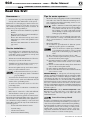
When calling or writing about the boiler
Please have boiler model number and series from boiler rating label and Consumer Protection (CP) number(s)
from boiler jacket, burner and controls. On page 35 of this manual is space to list CP number(s).
Homeowner —
Read and follow all information on pages 1 through 7 ONLY.
Service technician —
Read and follow ALL information in the entire manual.
Failure to follow all instructions in proper order can cause severe personal injury, death or
substantial property damage.
Using this manual
Hazard definitions
Packaged boilers: Available only in sizes 3 through 6, are factory assembled, completed with block, collector
hood, jacket, controls and trim (damper included, shipped loose inside boiler shipping
carton). Burner is ordered and shipped separately
Semi-packaged boilers: Available only in sizes 3 through 6, are shipped with block assembled with collector hood
and jacket installed. Control, trim, damper and burner are ordered and shipped separately
for field assembly.
Knocked-down boilers: Available in sizes 3 through 9, are shipped with block assembled only. All other components
are ordered and shipped separately for field assembly.

Part number 550-141-330/1220
3
SGO
OIL-FIRED NATURAL DRAFT STEAM BOILER — SERIES 4 — Boiler Manual
HOMEOWNER and SERVICE TECHNICIAN — read and follow completely.
Contents
Using this manual . . . . . . . . . . . . . . . . . . . . .2
When calling or writing about the boiler . . . . . . . .2
Packaged, Semi-packaged and Knocked-down boilers 2
Hazard denitions . . . . . . . . . . . . . . . . . . . . .2
Contents . . . . . . . . . . . . . . . . . . . . . . . . . .3
Read this rst ! . . . . . . . . . . . . . . . . . . . . . .4
Routine maintenance schedule. . . . . . . . . . . . . .5
Beginning each heating season . . . . . . . . . . . .5
Daily during heating season . . . . . . . . . . . . . .5
Weekly during heating season . . . . . . . . . . . . .5
Periodically during heating season . . . . . . . . . .5
End of heating season . . . . . . . . . . . . . . . . .5
Boiler shutdown . . . . . . . . . . . . . . . . . . . .5
Please read this before proceeding . . . . . . . . . . .6
Start-Up . . . . . . . . . . . . . . . . . . . . . . . .6
Check Daily . . . . . . . . . . . . . . . . . . . . . . .6
Check Monthly . . . . . . . . . . . . . . . . . . . . .6
Check Periodically . . . . . . . . . . . . . . . . . . .6
Troubleshooting . . . . . . . . . . . . . . . . . . . . . .7
Before installing boiler . . . . . . . . . . . . . . . . . .8
Installations must comply with . . . . . . . . . . . . .8
Before selecting boiler location . . . . . . . . . . . .8
Provide clearances around boiler (see Figure 2) . . .8
Provide air for combustion and ventilation . . . . . .9
Lay a foundation, if needed . . . . . . . . . . . . . .9
Air contamination . . . . . . . . . . . . . . . . . . . 10
Operation. . . . . . . . . . . . . . . . . . . . . . . . . 11
SGO with float-type low water cutoff . . . . . . . . 11
SGO with probe-type low water cutoff. . . . . . . . 12
Install boiler - Packaged boilers only . . . . . . . . . . . 13
Place boiler . . . . . . . . . . . . . . . . . . . . . .13
Perform hydrostatic pressure test . . . . . . . . . .13
Install boiler - Semi-packaged & Knocked-down boilers 14
Place boiler . . . . . . . . . . . . . . . . . . . . . .14
Tankless heater, if used. . . . . . . . . . . . . . . . 14
Perform hydrostatic pressure test . . . . . . . . . .16
Install jacket (Knocked-down boilers only) . . . . . 16
Install boiler controls . . . . . . . . . . . . . . . . .16
Install burner and chimney — all boilers . . . . . . . 18
Install burner (also refer to instructions
packed with burner) . . . . . . . . . . . . . . . . . 18
General chimney requirements. . . . . . . . . . . . 18
Connect breeching . . . . . . . . . . . . . . . . . . . 18
Connect breeching . . . . . . . . . . . . . . . . . .18
Connect steam piping. . . . . . . . . . . . . . . . . . 20
General piping information . . . . . . . . . . . . . . 20
Install piping . . . . . . . . . . . . . . . . . . . . . 20
To connect SGO boilers to indirect-fired
water heaters . . . . . . . . . . . . . . . . . . . . .20
Optional reservoir piping . . . . . . . . . . . . . . .23
Connect tankless heater piping . . . . . . . . . . . . 24
To pipe tankless heater. . . . . . . . . . . . . . . . 24
Connect wiring — general information . . . . . . . . 26
General wiring requirements . . . . . . . . . . . . .26
Thermostat wiring . . . . . . . . . . . . . . . . . . 26
Junction box (furnished) . . . . . . . . . . . . . . .26
Burner wiring . . . . . . . . . . . . . . . . . . . . .26
High temperature limit . . . . . . . . . . . . . . . . 26
Blocked vent shutoff switch . . . . . . . . . . . . . 27
Connect wiring (Float-type LWCO) . . . . . . . . . . . 28
Blocked vent shutoff switch (BVSS), when required 29
Connect wiring (Probe-type LWCO) . . . . . . . . . . 30
Blocked vent shutoff switch (BVSS), when required 31
OVD Vent damper wiring . . . . . . . . . . . . . . .32
Connect oil piping . . . . . . . . . . . . . . . . . . . . 32
General oil piping requirements . . . . . . . . . . .32
Oil piping connection at burner . . . . . . . . . . . 32
Start up. . . . . . . . . . . . . . . . . . . . . . . . . . 33
Steam water treatment . . . . . . . . . . . . . . . . 33
Fill the system . . . . . . . . . . . . . . . . . . . . 34
Tips for steam systems. . . . . . . . . . . . . . . . 34
Skim steam boiler. . . . . . . . . . . . . . . . . . . 34
To place in operation . . . . . . . . . . . . . . . . .34
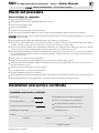
Check out procedure . . . . . . . . . . . . . . . . . . 35
Check off “Steps” as completed . . . . . . . . . .35
Installation and service certicate . . . . . . . . . . . 35
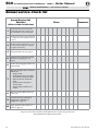
Annual service check list . . . . . . . . . . . . . . . . 36
Service and maintenance . . . . . . . . . . . . . . . . 37
General description of control operation . . . . . . 37
Burner adjustments . . . . . . . . . . . . . . . . . 37
Controls requiring annual service . . . . . . . . . . 37
Cleaning boiler flue ways. . . . . . . . . . . . . . . 38
Inspect . . . . . . . . . . . . . . . . . . . . . . . . .38
Reported problems . . . . . . . . . . . . . . . . . . 38
Boiler area . . . . . . . . . . . . . . . . . . . . . . 38
Piping . . . . . . . . . . . . . . . . . . . . . . . . .38
Service . . . . . . . . . . . . . . . . . . . . . . . . .39
Check/test . . . . . . . . . . . . . . . . . . . . . . .39
Check monthly . . . . . . . . . . . . . . . . . . . . . 39
Boiler and system piping . . . . . . . . . . . . . . . 40
Review with owner. . . . . . . . . . . . . . . . . . . 40
Boiler relief valve. . . . . . . . . . . . . . . . . . . . 40
Replacement parts . . . . . . . . . . . . . . . . . . . 41
Dimensions . . . . . . . . . . . . . . . . . . . . . . . 46
Ratings . . . . . . . . . . . . . . . . . . . . . . . . . . 47
Handling ceramic ber and berglass materials . . . 48

Part number 550-142-330/1220
4
SGO
OIL-FIRED NATURAL DRAFT STEAM BOILER — SERIES 4 — Boiler Manual
HOMEOWNER and SERVICE TECHNICIAN — read and follow completely.
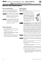
Tips for water systems —
• Check boiler and system piping for leaks. Continual makeup
water will reduce boiler life. Minerals can build up in sec-
tions, reducing heat transfer and causing cast iron to over-
heat, resulting in section failure.
Failure to maintain recommended pH and repair
leaks can cause section iron corrosion, leading to
section failure and leaks. Do not use petroleum-
based sealing or stop-leak compounds in boiler
systems. Damage to system components can result,
causing property damage.
• Boiler water pH 7.0 to 8.5 is recommended. For pH condi-
tions outside 7.0 to 8.5 range or unusually hard water areas
(above 7 grains hardness), consult local water treatment
company.
• When using antifreeze:
Use antifreeze especially made for hydronic systems.
Inhibited propylene glycol is recommended.
Do not use automotive, ethylene glycol, undiluted
or petroleum-based antifreeze. Severe personal
injury, death or substantial property damage can
result.
50% solution provides protection to about –30°F.
Local codes may require back-flow preventer or actual
disconnect from city water supply.
Determine quantity according to system water content.
Boiler water content is listed on back cover of Boiler
Manual.
Percent of solution will affect sizing of heat distribution
units, circulator and expansion tank.
Follow antifreeze manufacturer’s instructions.
Do not add cold water to hot boiler. Thermal shock can
cause sections to crack.
Saltwater Damage — The exposure of boiler components to
saltwater can have both immediate and long-term effects. While
the immediate effects of saltwater damage are similar to those
of freshwater (shorting out of electrical components, washing
out of critical lubricants, etc.), the salt and other contaminants
left behind can lead to longer term issues after the water is gone
due to the conductive and corrosive nature of the salt residue.
Therefore, Weil-McLain equipment contaminated with saltwater
or polluted water will no longer be covered under warranty and
should be replaced.
Electrical Damage — If any electrical component or wir-
ing
came into contact with water, or was suspected to have
come into contact with water, replace the boiler with a new
Weil-McLain boiler.
Frozen Water Damage Hazard
Residences or buildings that are unattended in severely cold
weather, boiler system components failures, power outages, or
other electrical system failures could result in frozen plumbing
and water damage in a matter of hours. For your protection,
take preventative actions such as having a security system
installed that operates during power outages, senses low
temperature, and initiates an effective action. Consult with
your boiler contractor or a home security agency.
Homeowner —
• For homeowner or person responsible for simple
start-up and routine maintenance of the system.
Instructions on 1 through page 7 must be followed to
assure proper operation of your boiler. See page 7 for
lists common problems and possible corrections. In
addition, it is your responsibility to:
• Have boiler and burner installed by a qualified
installer.
• Have boiler and burner serviced annually by a
qualified service technician.
• Review and understand start-up and routine
maintenance procedures with qualified service
technician.
• Perform routine maintenance as described on
page 5 and
Service technician —
• For a qualified service technician who has the nec-
essary equipment to check the boiler and system
performance, and is responsible for start-up and
service of boiler and system.
• All instructions in this manual must be followed to
assure proper operation of this boiler.
• Annually service boiler and burner to assure proper
operation. See page 36 for service record.
• Review and explain start-up and routine mainte-
nance procedures with homeowner.
Follow instructions below to prevent se-
vere personal injury, death or substantial
property damage:
• To avoid electric shock, disconnect electrical supply
to burner service switch and additional external
switches before performing service.
• To avoid severe burns, allow boiler to cool before
performing service.
• Do not block flow of combustion or ventilation air
to boiler.
• Boiler must be connected to a flue with sufficient
draft at all times to assure proper operation.
Do not use this boiler if any part has been under water.
Electrical and mechanical failures may cause electric
shock and fire risks. Immediately call a qualified ser-
vice technician to inspect chimney or vent, boiler and
burner. Have the boiler flue ways cleaned and have the
following replaced:
• all electrical and mechanical controls
• electrical wiring
• oil burner and controls
• insulation and chamber lining
Read this first!

Part number 550-141-330/1220
5
SGO
OIL-FIRED NATURAL DRAFT STEAM BOILER — SERIES 4 — Boiler Manual
HOMEOWNER and SERVICE TECHNICIAN — read and follow completely.
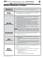
Routine maintenance schedule
Beginning
each heating season
Call a qualified service technician to perform annual service.
Daily
during heating season
Check that boiler area is free from combustible materials, gasoline
and other flammable vapors and liquids.
Weekly
during heating season
Check for and remove any obstructions to flow of combustion or
ventilation air to boiler.
Check that breeching is attached between boiler and chimney. If
breeching is loose or damaged, immediately turn off switch on
boiler and call service technician to repair.
Check for oil leaks in oil piping and around burner. If found, im-
mediately call qualified service technician to correct situation.
Check for water leaks in boiler and piping; also check for leaks
around tankless heater plate, if installed. If found, immediately call
service technician to repair.
Check float-type low water cutoff, when used: Refer to control
manufacturer’s instructions.
Scald potential. Do not blow down low water cutoff unless blow
down piping has been installed according to Boiler Manual. If
piping is not in place, call qualified service technician to install.
Periodically
during heating season
Test probe-type low water cutoff, when used: refer to control
manufacturer’s instructions.
End
of heating season
If tankless heater is installed, boiler will continue to operate. Check
for the following:
• All daily and weekly instructions listed on this page must be fol-
lowed.
• Burner motor may have to be oiled. Some motors are permanently
lubricated and do not need additional oil. Check for oiling instruc-
tions on burner or motor.
Boiler
shutdown
Do not drain boiler unless exposure to freezing temperatures will
occur.
Do not use antifreeze in steam systems.
Always keep manual fuel supply shut off if burner is shut down for
an extended period of time.
• Turn off switch at boiler and any external switch to boiler.
• Close fuel valves.
• Turn off water feed valve.
• Cover burner to protect from dust and dampness.

Part number 550-142-330/1220
6
SGO
OIL-FIRED NATURAL DRAFT STEAM BOILER — SERIES 4 — Boiler Manual
HOMEOWNER and SERVICE TECHNICIAN — read and follow completely.
Please read this before proceeding
Start-up
1. If burner does not fire, check for:
• Boilerswitchturnedoff?
• Fusesblownorbreakertripped?
• Thermostatsetbelowroomtemperature?
• Fuelvalvesturnedoff?
• Waternotvisibleingaugeglass?
• Notenoughoilintanktosupplyburner?
2. Correct problems found in step #1. If burner does
not fire, press the reset button on burner primary
control only once. Repeated presses will deposit oil
in chamber, creating a fire hazard.
Burner must never be fired when oil is in
combustion chamber. Immediately call a
qualified service technician.
3. If burner still does not fire, call a qualified service
technician.
Check daily
Boiler area
• Check that boiler area is free from combustible materials,
gasoline and other flammable vapors and liquids. Ensure
that no air-contaminating materials (see page 10) are
present in the area.
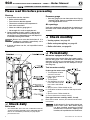
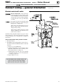
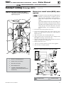
Figure 1 Boiler and components
Pressure gauge
• Pressure gauge must not show more than 15 psig
(normally 5 psig). Contact a qualified service techni-
cian if high pressure occurs.
Air openings
Verify that combustion and ventilation air openings to
the boiler room and/or building are open and unob-
structed.
Check monthly
• Venting system, see page 39.
• Boiler and system piping, see page 39.
• Boiler relief valve, see page 40.
Periodically
Oil motors equipped with oil cups
Burner motors may require oiling. Such motors are fit-
ted with oiling cups. Use a few drops only of SAE 20
detergent oil. Do not use household oils. Excessive
oiling can damage motors. Do not attempt to “fill up”
the oiling cup.
Test low water cutoff(s)
Probe-type low water cutoff
1. Turn off power to boiler
and wait 5 minutes.
2. Drain water to bottom of
gauge glass.
3. Turn on power.
4. Set thermostat to call for
heat. Red neon lamp on
low water cutoff should
light.
5. Wait 5 minutes. Boiler should not fire.
6. Refill boiler to correct water line. Red lamp should
go off.
7. Wait 5 minutes. Boiler should fire.
8. Return thermostat to normal setting.
Float-type low water cutoff (by others, if used)
Blow down control and test per control manufacturer’s
instructions.
Scald potential. Do not blow down low
water cutoff unless blow down piping
has been installed according to control
manufacturer’s instructions. If piping is not
installed, call a qualified service technician.

Part number 550-141-330/1220
7
SGO
OIL-FIRED NATURAL DRAFT STEAM BOILER — SERIES 4 — Boiler Manual
HOMEOWNER and SERVICE TECHNICIAN — read and follow completely.
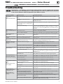
Troubleshooting
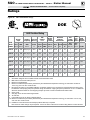
Common problems Common causes Possible corrections
Rapid cycling -
burner
turns on and off frequently
.
ermostat installed where dras or heat aect
reading.
Locate thermostat on inner wall away from heat sources or cool dras.
Heat anticipator setting in thermostat set
incorrectly.
Consult thermostat manufacturer instructions or set heat anticipator to
match current draw of circuit it is attached to. (Burner primary control, T-stat
switching relay coil, etc.).
Main and/or radiator vents not working properly
(one-pipe steam) or traps not working properly
(two-pipe steam).
Contact service technician to check, repair or replace air vents and traps.
Incorrect pressure limit setting. Set pressure cut-in and dierential according to system needs. Typical one and
two pipe systems need less than 2 psig. Typical cut-in setting is ½ -1 psi and
dierential of 1 psi. Try increasing dierential in ½ psi increments for longer
cycle times.
Frequent release of
water or steam through relief
valve.
Inoperative limit control.
If pressure in boiler is approaching 15 PSI, check pressure control setting,
operation & wiring. Replace if defective.
Incorrect or defective relief valve. Check for proper relief valve (15 psi). If opening at less than 15 psig, replace.
Needtofrequentlyadd
makeup water.
Leaks in boiler or piping.
Have qualied service technician repair leaks at once to avoid constant use of
makeup water.
Black or rust colored water
condition.
Black oxide or oxidation (rust) due to leaks in
boiler, air vents or piping. Improper pH.
Have qualied service technician repair leaks at once. Keep pH of water
between 7.0 to 8.5.
Popping or percolating noise
heard in boiler
.
Mineral deposits in sections due to constant use
of makeup water. Or incorrect pH.
Have qualied service technician de-lime boiler and repair leaks at once to avoid
constant use of makeup water and check ph (7.0 to 8.5).
Metal flakes found in vent
outlet or vent — flue way
corrosion.
Contaminated combustion air supply. Remove any contaminating products. See page10 of this manual.
Provide outside air for combustion.
Condensation of combustion gases in ue ways. Have a qualied service technician check burner nozzle and oil pump pressure
for proper ring rate and check/adjust combustion settings with analyzer.
Some radiators or baseboard
units do not heat.
Main or radiator air vents (one pipe system) or
traps (two pipe system) not operating correctly.
Have qualied service technician inspect, repair or replace faulty air vents or
traps.
Incorrect pressure limit setting. Set pressure cut in and dierential according to system needs. Typical one and
two pipe systems need less than 2 psig. Typical cut in setting is ½ -1 psi and
dierential of 1 psi.
Clogged piping, valves or radiator. Or inoperable/
closed radiator valve.
Have qualied service technician clean or replace clogged components.
Water disappearing from
gauge glass and back into
system through return piping.
Incorrect Hartford loop piping. Have qualied service technician pipe boiler exactly as shown in boiler manual.
Check-valve inoperative. Have qualied service technician clean or replace check-valve.
Vacuum-breaker inoperative. Have qualied service technician clean or replace vacuum breaker.
Violent waterline fluctuations
surging
OR
Water passing into steam
mains priming.
Dirt, oil or other impurities in water. Have qualied service technician skim boiler.
Waterline too high. Have qualied service technician adjust waterline to normal height.
Incorrect piping. Have qualied service technician pipe boiler exactly as shown in boiler manual.
Sudden release of boiler steam pressure by action
of zone valves.
Have qualied service technician adjust valve operating time or install slow-
opening valves.
Domestic water from
tankless heater is hot then
suddenly turns cold.
Or
Domestic water from
tankless heater is always
lukewarm.
Mineral deposits insulate internal waterways of
heater.
Have qualied service technician delime or replace coil.
Boiler stop-leak compound has been added to
boiler water and is insulating outside of coil.
Have qualied service technician remove and clean coil and drain and ush
boiler to remove stop-leak.
Incorrect mixing valve setting for tankless heater. Have qualied service technician adjust mixing valve setting.
Domestic ow rate too high.
Have qualied service technician install ow check valve set to rating of
tankless heater.
Incorrect setting on tankless heater control.
Have qualied service technician raise tankless control setting. Adjust
dierential on tankless control to lower setting.
Homeowners — The problems and corrections below represent common situations that can occur.
There may be others not listed below. It is important always to contact a qualified service technician
if you have any questions about the operation of your boiler or system.

Part number 550-142-330/1220
8
SGO
OIL-FIRED NATURAL DRAFT STEAM BOILER — SERIES 4 — Boiler Manual
HOMEOWNER and SERVICE TECHNICIAN — read and follow completely.
Top View
Walls
Floor
Ceiling
Wall
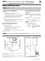
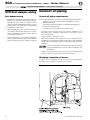
Figure 2 Recommended service clearances
24"
C
A
B
D D
D
24"
A Provide 6" minimum clearance for service, provide 12" minimum clearance for
burner door swing.
B Provide 6" minimum clearance for service.
C Provide 6" minimum clearance for service, provide 15" left side with tankless heater.
D Minimum clearance from vent pipe to combustible material: 6" for type “L” double-
wall vent, 9" for single-wall vent.
Before installing boiler
Installations must comply with
United States
• State and local plumbing, heating and electrical codes.
• National codes where applicable.
• Standard for Controls and Safety Devices for Automatically Fired
Boilers, ANSI/ASME CSD-1, – latest edition, when required.
• National Electrical Code, ANSI/NFPA 70, – latest edition
and any additional national, state or local codes.
Canada
• Canadian Standards Association, CSA B139, Installation Code for
Oil-Burning Equipment - latest edition.
• CSA C22.1 Canadian Electrical Code Part One - latest edition.
• Applicable local or provincial codes.
Before selecting boiler location
Check for nearby connections to:
• System water piping.
• Chimney. See page 18. Boiler can be top or back vented.
• Combustion and ventilation air supply. See page 9.
• Oil supply. See page 32 for oil line routing.
• Electrical power.
Check area around boiler. Remove any combustible materials, gasoline and
other flammable liquids.
Provide clearances around boiler
(see Figure 2)
Jacket cap must be in place on boiler to
avoid requiring an 9" minimum clearance
from back or top of boiler to combustible
material.
MINIMUM clearances from vent pipe to combustible
material:
• 6 inches — Type “L” double-wall vent
• 9 inches — Single-wall vent
Flue pipe clearances must take precedence
over jacket clearances.
Recommended SERVICE clearances:
• 24 inches — Front and top
• 6 inches — Left side, back and right side
• 15 inches — Left side with tankless heater
• 12 inches — Right side for burner door swing
radius
Failure to keep boiler area clear and free of combustible materials, gasoline and other flammable liquids and vapors
can result in severe personal injury, death or substantial property damage.
Homeowner — STOP! The procedures and information on this and following pages are intended only for a quali-
fied service technician who has the necessary equipment to inspect and adjust boiler and burner. A homeowner
should never attempt these procedures. The service technician must also read pages 1 through 7 before proceeding.

Part number 550-141-330/1220
9
SGO
OIL-FIRED NATURAL DRAFT STEAM BOILER — SERIES 4 — Boiler Manual
HOMEOWNER and SERVICE TECHNICIAN — read and follow completely.
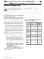
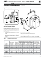
Table 1 Boiler foundation sizes
Provide air for combustion and ventilation
Do not install exhaust fan in boiler room.
Adequate combustion and ventilation air:
• Assures proper combustion.
• Reduces risk of severe personal injury or death from possible flue
gas leakage and carbon monoxide emissions.
Older buildings with single-pane windows, minimal weather-stripping
and no vapor barrier often provide enough natural infiltration and
ventilation without dedicated openings.
New construction or remodeled buildings are most often built tighter.
Windows and doors are weather-stripped, vapor barriers are used and
openings in walls are caulked. As a result, such tight construction is
unlikely to allow proper natural air infiltration and ventilation.
Follow state, provincial or local codes when sizing adequate combus-
tion and ventilation air openings. In absence of codes, use the follow-
ing guidelines when boiler is in a confined room (defined by NFPA
31 as less than 7200 cubic feet per 1 GPH input of all appliances in
area. A room 8 ft. high x 33.5 ft. x 33.5 ft. is 7200 cu. ft.):
• Provide two permanent openings — one within 12 inches of
ceiling, one within 12 inches of floor. Minimum height or length
dimension of each rectangular opening should be at least 3 inches.
• When inside air is used — each opening must freely connect with
areas having adequate infiltration from outside. Each opening
should be at least 140 sq. in. per 1 GPH input (1 sq. in. per 1000
Btu input) of all fuel-burning appliances plus requirements for
any equipment that can pull air from room (including clothes
dryer and fireplace).
When outside air is used — connect each opening directly or by ducts
to the outdoors or to crawl or attic space that freely connects with
outdoors. Size per below:
• Through outside wall or vertical ducts — at least 35 sq. in. per
1 GPH input (1 sq. in. per 4000 Btu input) of all fuel-burning
appliances plus requirements for any equipment that can pull
air from room (including clothes dryer and fireplace).
• Through horizontal ducts — at least 70 sq. in. per 1 GPH
boiler input (1 sq. in. per 2000 Btu input) of all fuel-burning
appliances plus requirements for any equipment that can pull
air from room (including clothes dryer and fireplace).
• Where ducts are used, they should have same cross-sectional
area as free area of openings to which they connect. Com-
pensate for louver, grille or screen blockage when calculating
free air openings. Refer to their manufacturer’s instructions
for details. If unknown, use:
• Wood louvers, which provide 20-25% free air.
• Metal louvers or grilles, which provide 60-75% free air.
Lock louvers in open position or interlock with equipment to prove
open before boiler operation.
Lay a foundation, if needed
Boiler may be installed on non-carpeted combustible
flooring.
For residential garage installation, install boiler so burner is
at least 18 inches above floor to avoid contact with gasoline
fumes.
A level concrete or masonry foundation is required when:
• Floor could possibly become flooded.
• Non-level conditions exist.
Solid concrete blocks can be used to create a pad.
Boiler
model
Length
inches
Width
inches
Minimum
height
inches
SGO-3
17 22 2
SGO-4
20 22 2
SGO-5
23 22 2
SGO-6
26 22 2
SGO-7
29 22 2
SGO-8
32 22 2
SGO-9
35 22 2
Before installing boiler (continued)

Part number 550-142-330/1220
10
SGO
OIL-FIRED NATURAL DRAFT STEAM BOILER — SERIES 4 — Boiler Manual
HOMEOWNER and SERVICE TECHNICIAN — read and follow completely.
Air contamination
Please review the following information on potential
combustion air contamination problems.
See Table 2 for products and areas which may cause
contaminated combustion air.
To prevent potential of severe personal injury
or death, check for products or areas listed
below before installing boiler. If any of these
contaminants are found:
• removecontaminantspermanently.
— OR —
• isolateboilerandprovideoutsidecombustionair.
See national, provincial or local codes for further
information.
• Contact your qualified service technician to install
an outside air kit (if available) for the burner. An
outside air kit allows ducting of outside air directly
to the burner.
Before installing boiler continued
Table 2 Corrosive contaminants and likely locations
Products to avoid
Spray cans containing chloro/uorocarbons
Permanent wave solutions
Chlorinated waxes/cleaners
Chlorine-based swimming pool chemicals
Calcium chloride used for thawing
Sodium chloride used for water softening
Refrigerant leaks
Paint or varnish removers
Hydrochloric acid/muriatic acid
Cements and glues
Antistatic fabric softeners used in clothes dryers
Chlorine-type bleaches, detergents, and cleaning solvents
found in household laundry rooms
Adhesives used to fasten building products and other similar
products
Areas likely to have contaminants
Dry cleaning/laundry areas and establishments
Swimming pools
Metal fabrication plants
Beauty shops
Refrigeration repair shops
Photo processing plants
Auto body shops
Plastic manufacturing plants
Furniture renishing areas and establishments
New building construction
Remodeling areas
Garages with workshops

Part number 550-141-330/1220
11
SGO
OIL-FIRED NATURAL DRAFT STEAM BOILER — SERIES 4 — Boiler Manual
HOMEOWNER and SERVICE TECHNICIAN — read and follow completely.
Operation
SGO with float-type low water cutoff
1. If burner does not fire, check for:
• Switch on boiler or additional shut-off switches turned
off.
• Fuses or breaker switch tripped.
• Thermostat set below room temperature.
• Fuel valves turned off.
• Not enough oil in tank to supply burner.
• No water in gauge glass.
2. Correct problems found in Step #1. If burner does not fire,
press reset button on burner primary control only once.
Repeated presses will deposit oil in combustion chamber.
Burner must never be fired when oil is in combus-
tion chamber. Immediately call qualified service
technician.
3. If burner still does not fire, call qualified service technician.
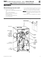
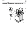
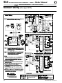
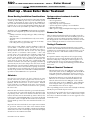
Figure 3 SGO boiler with float-type low water cutoff (see Figure 4, page 12 for probe-type low water cutoff)
Gauge glass
Steam relief valve
(on back of boiler)
Tankless heater
control
located
in tankless
heater plate
(sizes 3-5)
or in tapping in
back section
(sizes 6-9)
Float-type
Low water cutoff
Pressure
control
Pressure
gauge
Burner
primary
control
Service
switch
On boiler
Reset button
on burner
primary
control
Burner
disconnect
plug

Part number 550-142-330/1220
12
SGO
OIL-FIRED NATURAL DRAFT STEAM BOILER — SERIES 4 — Boiler Manual
HOMEOWNER and SERVICE TECHNICIAN — read and follow completely.
2. Correct problems found in Step #1. If burner does not fire,
press reset button on burner primary control only once.
Repeated presses will deposit oil in combustion chamber.
Burner must never be fired when oil is in combus-
tion chamber. Immediately call qualified service
technician.
3. If burner still does not fire, call qualified service technician.
SGO with probe-type low water cutoff
1. If burner does not fire, check for:
• Service switch on boiler or additional switches turned off.
• Fuses or breaker switch tripped.
• Thermostat set below room temperature.
• Fuel valves turned off.
• Not enough oil in tank to supply burner.
• No water in gauge glass.
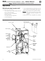
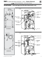
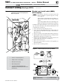
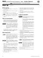
Figure 4 SGO boiler with probe-type low water cutoff (see Figure 3, page 11 for float-type low water cutoff)
Steam relief valve
(on back of boiler)
Gauge glass
Probe-type
low water
cutoff
Reset button
on burner
primary
control
Tankless heater
control
located in
tankless heater
plate
(sizes 3-5)
or in tapping in
back section
(sizes 6-9)
Pressure control
Pressure gauge
Burner
primary
control
Burner
disconnect
plug
Service
switch
on boiler
Operation (continued)

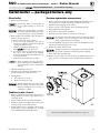
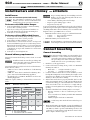
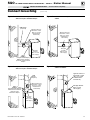
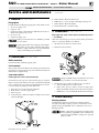
Figure 5 Change from back flue outlet to top flue outlet (optional)
Instructions for Packaged boilers continued on page 18.
Install boiler — packaged boilers only
Part number 550-142-330/1220
13
SGO
OIL-FIRED NATURAL DRAFT STEAM BOILER — SERIES 4 — Boiler Manual
SERVICE TECHNICIAN ONLY — read and follow completely.
Place boiler
1. Remove boiler from pallet.
Do not drop boiler or bump jacket on
floor or pallet. Damage to boiler can
result.
Smaller sized boilers may be top heavy.
Use caution when handling to avoid mi-
nor personal injury or property damage.
2. Boiler is shipped for back flue outlet. To change to
top flue outlet (see Figure 5):
a. Remove jacket cap on top of boiler.
b. Loosen two screws holding flue cap strap to
collector hood. Remove strap and flue cap from
opening. Re-tighten screws.
c. Check rope placement inside flue cap.
(Read
under Step #5 below).
d. Loosen two (2) screws on back flue outlet. Set
flue cap on outlet. Install strap by engaging
slots in screws. Tighten screws. Make sure cap
is securely installed.
e. Snap jacket cap in back outlet opening.
Jacket cap must be in place on boiler to
avoid requiring an 18" minimum clear-
ance from back of boiler to combustible
material.
3. Check level. Shim legs, if needed.
4. Check for secure placement of insulation on tar-
get wall, chamber floor and burner door.
5. Visually check:
a. Flue collector hood seal.
b. Burner mounting door seal.
Obtain gas-tight seal to prevent possible
flue gas leakage and carbon monoxide
emissions, which can lead to severe per-
sonal injury or death.
Tankless heater, if used
1. Remove tankless heater knockout in left side of
jacket panel and, for SGO-6 only, tankless heater
control knockout.
2. Remove tankless heater cover plate and gasket.
3. Install new gasket and tankless heater over studs
around opening. Secure with 3/8" nuts.
4. Install tankless heater operating control where
shown on page 25. If not furnished, use operating
control with maximum 10°F differential.
Perform hydrostatic pressure test
1. Remove steam pressure gauge furnished with boiler. Install water pres-
sure gauge for test only. Be sure gauge can handle test pressure.
2. Install air vent in tapping on top of boiler.
3. Remove pressure control and low water cutoff. Plug tappings.
4. Plug supply and return tappings.
5. Drain valve is already factory-installed.
6. Fill boiler. Vent all air. Pressure test boiler at 45-55 psig.
Do not leave boiler unattended. Cold water fill can expand
and damage cast iron, resulting in severe personal injury,
death or substantial property damage.
7. Check for maintained gauge pressure for more than 10 minutes. Visu-
ally check for leaks if gauge pressure drops.
8. Drain boiler. Repair leaks if found.
Using petroleum-based compounds to repair leaks can dam-
age system components, resulting in property damage.
9. Retest boiler after repairing leaks.
10. Remove pressure gauge, air vent and plugs. Re-install steam pressure
gauge, pressure control and low water cutoff furnished with boiler.

Part number 550-142-330/1220
14
SGO
OIL-FIRED NATURAL DRAFT STEAM BOILER — SERIES 4 — Boiler Manual
SERVICE TECHNICIAN ONLY — read and follow completely.
Fiberglass wool and ceramic fiber materials are
possible cancer hazards. See warning on page 48.
Place boiler
1. Semi-packaged SGO-3 through 6 — position on site.
Smaller sized boilers may be top heavy. Use caution
when handling to avoid minor personal injury or
property damage.
a. Boiler is shipped for back flue outlet. To change to top flue
outlet (see Figure 6, page 15):
• Loosen two (2) screws holding flue cap strap
to collector hood. Remove strap and flue cap from
opening. Re-tighten screws.
• Check rope placement inside flue cap.
(Read
under Step #3 at right).
• Loosen two (2) screws on back flue outlet. Set flue
cap on outlet. Install strap by engaging slots in screws.
Tighten screws. Make sure cap is securely installed.
2. Knocked-down SGO-7, 8 & 9 — split the assembled block for
easier handling (see Figure 6):
a. Open burner mounting door and using utility knife, slit
floor insulation at joint to be separated.
b. Remove 5½" draw rod and the longest draw rod from each
side. Pull block apart. Save draw rods, nuts, washers and
sealing rings for reassembly.
c. Move divided block to location.
d. Clean port openings with clean rag.
Do not use petroleum-based compounds to clean
openings. Damage to system components can result
causing property damage.
e. Place rings in port openings. If ring slips out of groove,
stretch ring gently for several seconds, then place in groove.
f. Position sections so aligning lugs fit into sockets of next
section. Make sure sealing rope is in good condition and
in position.
g. Oil threads on draw rods. Install washer and nut on end
to be tightened. Use nut only on other end.
h. With wrench at washer/nut end, uniformly
tighten nuts starting with 5½" rod at large port, 5½" rod
at small port, bottom long rod and finally top long rod.
Install boiler – Semi-packaged and Knocked-down boilers only
i. Torque on both 5½” rods and bottom long rod should
be 50-60 ft. lbs.; long top rod should be 20-25 ft. lbs. Do
not back-off nuts.
j. Metal-to-metal contact should be made around port
openings. If gap does exist, it should be less than .020”.
Check with feeler gauge.
k. If gap around port openings exceeds .020”, check for dirt
on port openings, sockets or misaligned lugs. If corrections
are made and gap still exists, contact our Technical Services
group for assistance before continuing installation.
3. Knocked-down SGO-3 through 9 — install flue collector hood
(see Figure 6):
Obtain gas-tight seal to prevent possible flue gas
leakage and carbon monoxide emissions, leading
to severe personal injury or death.
a. Thread Tinnerman clip on screw so that clip fits snugly
in notch of hold-down lug. Screw must not turn.
b. Remove paper on sealing rope. Starting at back section
near flue collar, position sealing rope around top of block
with adhesive side to sections. Do not stretch rope. Make
sure rope ends meet. Trim excess rope.
c. Position flue collector hood on top of boiler sections and
over screws and clips as shown in Figure 6.
d. Install washers and nuts. Tighten nuts until collector hood
makes contact with Tinnerman clip.
e. Position flue cap
• Back flue outlet boiler — Position flue cap and strap
over opening in flue collector hood. Make sure rope
in cap is in place and in good condition. Tighten strap
to hood with screws provided.
• Top flue outlet boiler — Position flue cap and strap
over opening in back section. Make sure rope in cap is
in place and in good condition. Tighten strap to boiler
with screws provided in section. Install remaining
screws in holes in flue collector hood.
4. Check level. Shim legs, if needed.
Tankless heater, if used
1. SGO-3 through 6 — remove knockout in left side jacket panel,
and for SGO-6 only, remove tankless heater control knockout.
2. Remove tankless heater cover plate and gasket.
3. Install new gasket and tankless heater over studs around open-
ing. Secure with 3/8” nuts.

Part number 550-142-330/1220
15
SGO
OIL-FIRED NATURAL DRAFT STEAM BOILER — SERIES 4 — Boiler Manual
SERVICE TECHNICIAN ONLY — read and follow completely.
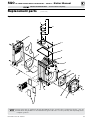
Figure 6 Change from back flue outlet to top flue outlet (optional)
Install boiler – Semi-packaged and Knocked-down boilers only (continued)
Sealing
rope in
groove
inside cap
Flue
cap
Flue cap
strap
Flue
collector
hood
Sealing
rope with
adhesive
tape
Nut
Washer
Tinnerman
clip
Screw
Hold-down
lug
Separate
block
here
for easier
handling

Part number 550-142-330/1220
16
SGO
OIL-FIRED NATURAL DRAFT STEAM BOILER — SERIES 4 — Boiler Manual
SERVICE TECHNICIAN ONLY — read and follow completely.
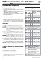
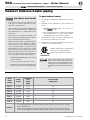
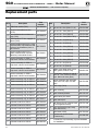
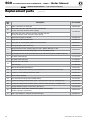
Location Size Function
A1 1½" Skim tapping
A2 2½" Supply piping (sizes 3 - 9)
A3 2½" Supply piping (sizes 6 - 9)
B1 1½" Plugged
B2 2" Return piping
E1 & E2 ½" Float LWCO
E1 ½"
Steam pressure gauge and limit
Control when using probe LWCO
E2 ½" Plugged when using probe LWCO
H ¾" Drain valve
L ¾"
Steam pressure gauge and limit
Control when using float LWCO
Plugged when using probe LWCO)
P ¾" Probe LWCO (plugged when using float LWCO)
R ¾" Relief valve
S1 & S2 ½" Gauge glass
U1 1"
Indirect-fired water heater/ hot water
baseboard supply
U2 ¾"
Operating control for tankless heater (sizes
6-9) or operating control for indirect-fired water
heater (sizes 3-9)
U3 ¾"
Operating control for tankless heater (located
in heater plate — sizes 3-5)
Perform hydrostatic pressure test
1. Refer to Figure 7 and Control Tapping Table 3, to
install:
a. Boiler drain.
b. Water pressure gauge (test only). Be sure gauge
can handle test pressure.
c. Air vent in tapping on top of boiler.
d. Plugs in remaining tappings.
2. Fill boiler. Vent all air. Pressure test boiler at 45-55
psig.
Do not leave boiler unattended. Cold
water fill could expand and damage cast
iron, resulting in severe personal injury,
death or substantial property damage.
3. Check for maintained gauge pressure for more
than 10 minutes. Visually check for leaks if gauge
pressure drops.
4. Drain boiler. Repair leaks if found.
Do not use petroleum-based compounds
to repair leaks. Damage to system com-
ponents can result, causing property
damage.
5. Re-test boiler after repairing leaks.
6. Remove pressure gauge, air vent and plugs from
tappings used for controls.
7. Visually check:
a. Sealing rope placement
b. Metal-to-metal contact around port openings.
c. Flue collector hood seal.
d. Burner mounting door seal.
Obtain gas-tight seal to prevent possible
flue gas leakage and carbon monoxide
emissions, which can lead to severe per-
sonal injury or death.
Table 3 Control tappings (see Figure 7, page 17 for locations)
Install jacket
(Knocked-down boilers only)
Before installing jacket, remove burner mounting door.
See jacket instructions for details.
Install boiler controls
See control tapping location, Figure 7, control tappings,
Table 3, and Figure 8 or Figure 9 on page 17 to install
controls.
1. Do not use Teflon tape to install probe-type low
water cutoff; it will cause low water cutoff to work
improperly.
2. Install tankless heater control if tankless heater is
used. If not furnished, use operating control with
maximum 10°F differential.
3. Make sure gauge glass is last control installed to
prevent breakage.
4. Affix Consumer Protection (CP) number label(s)
on jacket front panel.
Install boiler – Semi-packaged and Knocked-down boilers only (continued)

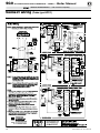
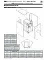
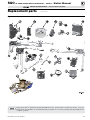
Figure 7 Control tapping
locations
(for use with
Table 3, page 16)
U3
Front Section
A1 A2S1
L
P
B1
H
S2
E2
E1
Back Section
R U1
U2
A3
B2
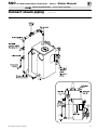
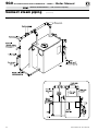
Figure 8 Steam boiler controls with float-type LWCO (optional tankless heater
control)
Figure 9 Steam boiler controls with probe-type LWCO (optional tankless heater
control)
Siphon
SGO-3 to SGO-5
tankless heater
control
SGO-6 to SGO-9
tankless heater
control
Steam pressure
Steam pressure
Probe-type
low water
cutoff
Gauge glass
and cocks
Drain valve
Part number 550-142-330/1220
17
SGO
OIL-FIRED NATURAL DRAFT STEAM BOILER — SERIES 4 — Boiler Manual
SERVICE TECHNICIAN ONLY — read and follow completely.
Install boiler – Semi-packaged and Knocked-down boilers only (continued)
SGO 3-5 tankless
heater control
location
SGO 6-9 tankless
heater control
location
Float-type low
water cutoff
Steam pressure
control
Steam pressure
gauge
Gauge glass
and cocks
Drain valve
Siphon

Part number 550-142-330/1220
18
SGO
OIL-FIRED NATURAL DRAFT STEAM BOILER — SERIES 4 — Boiler Manual
SERVICE TECHNICIAN ONLY — read and follow completely.
Connect breeching
Connect breeching
Long horizontal breechings, excessive number of tees
and elbows, or other obstructions restricting combus-
tion gas flow can result in possibility of condensation,
flue gas leakage and carbon monoxide emissions,
which can lead to severe personal injury or death.
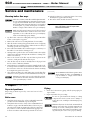
1. Install two (2) flue pipe brackets.
2. Connect full-sized breeching when possible. See Minimum
Chimney Size Table 4.
• Back outlet — see Figures 10 and 11, page 19.
• Top outlet — see Figures 13 and 12, page 19.
3. Connection must be made above bottom of chimney to avoid
blockage. Breeching must not enter chimney far enough to cause
obstruction. Use thimble or slip joint where breeching enters
chimney to allow removal for cleaning.
4. When burner and boiler are properly installed, draft over fire
will be approximately -0.01" to -0.02" W.C. Install barometric
control in breeching, per control manufacturer’s instructions,
when excess draft needs to be relieved or to comply with ap-
plicable codes and regulations. Use draft gauge to adjust proper
opening.
5. An induced draft fan for the chimney may be necessary if:
• Excessive resistance to flow of combustion gases can be
expected.
• Cross-sectional area of chimney is smaller than minimum
recommended.
• Chimney height is less than recommended.
Seal all vent joints. Interlock burner with fan opera-
tion.
6. Boiler models SGO-3 through SGO-7 require the installation of
the Field Controls OVD-7 damper, Weil-McLain part number
381-800-515, which is provided with Packaged boilers, sold
separately for Semi-packaged and Knocked-down boilers.
Refer to Figures 10 and 13, page 19.
Install burner
(also refer to instructions packed with burner)
Use only burners specified for use on Weil-
McLain oil boilers. Contact individual burner
manufacturers for proper burner selections.
For burners with OEM welded flanges:
1. Secure mounting flange and gasket to burner mounting
door. Use three (3) bolts provided.
2. Open door to verify secure placement of insulation on
target wall, chamber floor and burner mounting door.
3. Securely close door and tighten nut.
For burners without OEM welded flanges:
1. Secure universal mounting flange and gasket to burner
mounting door. Use three (3) bolts provided.
2. Secure burner on flange with three (3) bolts.
3. Position burner so end of air tube is level to 1½-degree tilt
down toward chamber. Open door to verify burner position.
End of air tube should be flush to ¼" recessed from inside
wall of burner door refractory. Check for secure placement
of insulation on target wall, chamber floor and burner
mounting door.
4. Securely close door and tighten nut.
General chimney requirements
Designed for natural draft firing. Connect boiler to vertical
chimney.
Insufficient draft can cause flue gas leakage and
carbon monoxide emissions, which will lead to
severe personal injury or death.
Use vent material approved by local codes for oil-fired burners.
In their absence, refer to:
• NFPA 31- latest edition, Installation of Oil-Burning
Equipment.
• NFPA 211- latest edition, Standard for Chimneys, Fire-
places, Vents and Solid Fuel Burning Appliances.
• In Canada, refer to CSA B139, Installation Code for Oil-
Burning Equipment.
NFPA 211 requires chimney to be lined before connected to
boiler.
Inspect existing chimney before installing new boiler.
Failure to do any of the following will result in severe
personal injury or death.
• Clean chimney, including removal of blockage.
• Repair or replace damaged pipe or liner.
• Repair mortar and joints.
To prevent downdrafts, extend chimney at least 3 feet above highest
point where it passes through roof and 2 feet higher than any portion
of building within 10 feet. Increase chimney cross-sectional area and
height at least 4% per 1,000 feet above sea level.
• Minimum clearances from vent pipe to combustible material:
• 6 inches — Type “L” double-wall vent
• 9 inches — Single-wall vent
• Minimum chimney sizes should be used.
Oversized chimneys, outside masonry chimneys and/or
derated inputs can result in condensation in chimney.
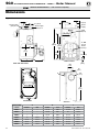
Boiler
model
number
Minimum
breeching
diameter
(Note 3)
Minimum
chimney size Minimum
chimney
heightRect. Round
SGO-3 5"
8" x 8"
(Note 1)
6" 15'
SGO-4 6"
SGO-5 6"
8" x 8"
(Note 1)
7" 15'SGO-6
7"
SGO-7
SGO-8
7"
8" x 12"
(Note 2)
7" 20'
SGO-9
NOTES:
1. 6¾” x 6¾” inside liner.
2. 6½” x 10½” inside liner.
3. Flue collar on boiler is 7” diameter.
Table 4 Minimum chimney sizes
Install burners and chimney — all boilers

Part number 550-142-330/1220
19
SGO
OIL-FIRED NATURAL DRAFT STEAM BOILER — SERIES 4 — Boiler Manual
SERVICE TECHNICIAN ONLY — read and follow completely.
Figure 10 Back outlet breeching connection for
SGO-3 through 7 with OVD damper.
Connect breeching (continued)
Figure 11 Back outlet breeching connection for SGO-8 and
SGO-9
Figure 12 Top outlet breeching connection for
SGO-8 and SGO-9
Figure 13 Top outlet breeching connection for
SGO-3 through 7 with OVD damper.
Typical location for
barometric control
(Also see control
manufacturer’s
instructions)
Flue pipe
bracket
(One on each
side of pipe)
Typical location for
barometric control
(Also see control
manufacturer’s
instructions)
Flue pipe bracket
(One on each
side of pipe)
0251-056_OVD
OVD Damper
(Required)
BVSS
(WMO-1)
(Integrated with damper)
BVSS must be installed
upstream of the barometric
damper
.
Typical location for
barometric control
(Also see control
manufacturer’s
instructions)
Flue pipe
bracket
(One on each
side of pipe)
0250-056_OVD
OVD
Damper
(Required)
Flue pipe
bracket
(One on each
side of pipe)
Typical location for
barometric control
(Also see control
manufacturer’s
instructions)
BVSS
(WMO-1)
(Integrated with damper)
BVSS must be installed
upstream of the
barometric damper
.

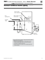
General piping information
• Hartford Loop piping arrangement and wet return are required for
steam boilers.
• Maintain 24-inch minimum from waterline to bottom of header
(minimum 50
7
/8" from floor or top of foundation).
• When using condensate receiver, feed pump must be energized by
boiler-mounted pump control.
• Use swing joints in steam piping.
• If installation is to comply with ASME or Canadian requirements, an
additional pressure limit control is needed. Install control between
existing pressure control and pressure gauge. Control must be installed
with siphon (supplied with boiler) between control and boiler. Set
control to minimum of 5 psi above set point of existing control and
maximum setting of 15 psi. Wire as shown on boiler wiring diagram.
Install piping
1. See Table 5 at right and Figure 14, page 21 or Figure 15, page 22.
Improperly piped systems or undersized piping can con-
tribute to erratic boiler operation and possible boiler
or system damage. Piping system must be installed as
shown, using minimum pipe sizes shown. Consult your
Weil-McLain distributor or sales office before installing
alternate piping.
2. Install relief valve vertically in “R” tapping on back of boiler. See
Figure 14 or Figure 15 and also refer to tag attached to relief valve for
manufacturer’s instructions.
Pipe relief valve discharge line near floor close to floor drain
to eliminate potential of severe burns. Do not pipe to any
area where freezing could occur. Do not plug, valve or place
any obstruction in discharge line.
3. Float-type low water cutoff only — install blow down line in bottom
of cutoff. See Figure 14 or Figure 15 and also refer to low water cutoff
manufacturer’s instructions for details.
Pipe blow down line near floor close to floor drain to eliminate
potential of severe burns. Do not pipe to any area where freez-
ing could occur. Do not plug, valve or place any obstruction
in discharge line.
To connect SGO boilers to indirect-fired water
heaters
Install and wire per water heater manual provided with water heater.
If boiler already has a tankless heater installed:
• Remove tankless heater and install cover plate.
OR
• Leave tankless heater installed. Drain coil and remove piping. Do not
plug holes in tankless heater front plate.
Connect steam piping
Table 5 Steam piping size table
One and two-pipe systems
Boiler
Model
Number
Riser Pipe
Size
(Note 1)
Header
Pipe Size
“H”
(Note 2)
Equalizer
Pipe
Size
“J”
A B
SGO-3
2½"
(Note3)
— 2½” 1½"
SGO-4
2½"
(Note3)
— 2½" 1½"
SGO-5 2½" — 3" 1½"
SGO-6 2½" 2½" 3" 1½"
SGO-7 2½" 2½" 3" 1½"
SGO-8 2½" 2½" 3" 1½"
SGO-9 2½" 2½" 3" 1½"
One-pipe counter ow systems
SGO-3 2½" — 2½” 1½"
SGO-4 2½" — 2½" 1½"
SGO-5 2½" — 3" 1½"
SGO-6 2½" 2½" 4" 1½"
SGO-7 2½" 2½" 4" 1½"
SGO-8 2½" 2½" 4" 1½"
SGO-9 2½" 2½" 4" 1½"
Note1
Based on ASHRAE Fundamentals
Handbook recommendations, allowing ½
oz. pressure drop at 0 psig.
Note2
Based on ASHRAE Fundamentals
Handbook recommendations, allowing 2
oz. pressure drop per 100 feet of pipe at 3.5
psig. Maintain minimum 24" height from
waterline to bottom of header.
Note3
Can be reduced to 2".
Part number 550-142-330/1220
20
SGO
OIL-FIRED NATURAL DRAFT STEAM BOILER — SERIES 4 — Boiler Manual
SERVICE TECHNICIAN ONLY — read and follow completely.
Page is loading ...
Page is loading ...
Page is loading ...
Page is loading ...
Page is loading ...
Page is loading ...
Page is loading ...
Page is loading ...
Page is loading ...
Page is loading ...
Page is loading ...
Page is loading ...
Page is loading ...
Page is loading ...
Page is loading ...
Page is loading ...
Page is loading ...
Page is loading ...
Page is loading ...
Page is loading ...
Page is loading ...
Page is loading ...
Page is loading ...
Page is loading ...
Page is loading ...
Page is loading ...
Page is loading ...
Page is loading ...
-
 1
1
-
 2
2
-
 3
3
-
 4
4
-
 5
5
-
 6
6
-
 7
7
-
 8
8
-
 9
9
-
 10
10
-
 11
11
-
 12
12
-
 13
13
-
 14
14
-
 15
15
-
 16
16
-
 17
17
-
 18
18
-
 19
19
-
 20
20
-
 21
21
-
 22
22
-
 23
23
-
 24
24
-
 25
25
-
 26
26
-
 27
27
-
 28
28
-
 29
29
-
 30
30
-
 31
31
-
 32
32
-
 33
33
-
 34
34
-
 35
35
-
 36
36
-
 37
37
-
 38
38
-
 39
39
-
 40
40
-
 41
41
-
 42
42
-
 43
43
-
 44
44
-
 45
45
-
 46
46
-
 47
47
-
 48
48


Weil-McLain SGO Series 4 Oil-Fired Steam Boiler User manual
- Type
- User manual
Ask a question and I''ll find the answer in the document
Finding information in a document is now easier with AI
Related papers
-
Weil-McLain SGO Oil Boiler User manual
-
-
-
-
-
Weil Mclain WTGO User guide
-
-
-
-
Other documents
-
Lennox GWB84-IE Non-Condensing Boiler Installation guide
-
Dunkirk Excelsior EXB Series Installation & Operation Manual
-
US Boiler 204NI-A2 Installation guide
-
UTICA BOILERS TriFire TRB 3 Installation & Operation Manual
-
Slant/Fin BOILERS User manual
-
-
Bryant BW4 Owner's manual
-
-
-
 Rand and Reardon RRG130 Installation guide
