Page is loading ...

Tools Required: Phillips Screwdriver, Insulated Wire Connectors (Wire Nuts
®
),
Wire Strippers, Wire Cutters
PLEASE READ THROUGH THESE INSTRUCTIONS BEFORE PROCEEDING
WITH INSTALLATION OF THE “SBFT2” THERMOSTAT INTO A CADET
SERIES “F” BASEBOARD
For All Applications
The thermostat needs to be mounted into the same junction
box (wiring compartment) as the supplied electrical power.
Both junction boxes are equipped with a ground screw.
The installation of the SMART-BASE thermostat may require
a slight adjustment of the panel across the front of the heater,
to allow the thermostat to fit into the junction box unobstructed.
To do so, remove both junction box covers and unlatch the
bottom of the panel from its hangers. (Use a rubber-coated
tool, or hammer handle to remove the panel. Carefully pry
upward to remove.) Next, slide it back out of the junction box
opening to be used for the thermostat until its edge is just
hanging over the partition. Hold the panel and snap it back
on to its hangers. The thermostat will now have enough room
to fit into the junction box opening.
Replacing Existing BTF Thermostat Control
1. Remove screw attaching the existing BTF assembly
(thermostat and plate) to the baseboard case and carefully
pull it back to expose the wiring and connections. (Test with
meter or circuit tester to verify that no electrical power is
present before proceeding.)
2. If the power supply has been brought into the baseboard
at this junction box, undo the wiring connections and
remove the old thermostat assembly. Follow the appropriate
wiring diagram (“FIGURE A” for left end attachment,
“FIGURE B” for right end attachment) and the following
instructions “Baseboard/Thermostat Wiring” below to
connect the SBFT2 to the baseboard and power supply.
When using electrical appliances, basic precautions should always be followed to reduce the risk of fire, electric shock, and
injury to persons, including the following:
Read all instructions before using this heater and thermostat.
All electrical work and materials must comply with the National Electric Code (NEC), the Occupational Safety and Health Act
(OSHA), and all state and local codes.
&%+(*,-"-
InstallatIon InstructIons
3. If the power supply has not been brought into the baseboard
at this junction box, remove the old thermostat assembly by
removing the wiring connections. The new thermostat
(SBFT2) must be located in the same junction box as the
supplied electrical power; therefore, strip 1/2” of insulation
from the two loose leads (created when the thermostat was
removed) and join the two wires back together using a wire
connector. Remove the end plate from the other junction
box and apply it to the junction box where the thermostat
was removed. Follow the appropriate wiring diagram
(“FIGURE A” for left end attachment, “FIGURE B” for right
end attachment) and the following further instructions
“Baseboard/Thermostat Wiring” to connect the SBFT2 to
the baseboard and power supply.
As Part of New Installation
Install the Cadet “F” series baseboard heater according to
the installation instructions supplied with the product. Keep
in mind the SBFT2 thermostat needs to be mounted into the
same junction box (wiring compartment) as the supplied
electrical power. Both junction boxes are equipped with a
ground screw.
WARNING
Turn the electrical power off at the electrical panel board (circuit breaker or fuse box) and lock or tag the
panel board door to prevent someone from turning on power while you are working on the heater. Failure
to do so could result in serious electrical shock, burns, or possible death. If you are uncomfortable work-
ing with electrical appliances, unable to follow these guidelines, or do not have the necessary equip-
ment, consult a licensed electrician.
000#"$%-#*#*(%'*1 ")#*./%+!

Baseboard/Thermostat Wiring
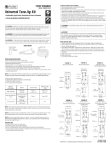
Thermostat in left junction box: (Figure A)
1. Locate and cut closed end splice of wires containing limit lead wire
and return wire (wire behind deflector). Strip 1/2” of insulation from
these two cut lead wires.
a. Join the lead wire from the limit with the lead wire from thermostat
terminal J5L2 with a connector.
b. Join the return wire (wire behind deflector) with the lead wire from
thermostat terminal J1T1 with a connector.
2. Connect the grounding lead of the power supply to the supplied
grounding screw.
3. Connect each of the remaining two power supply leads to each
lead from the thermostat rocker switch with a wire connector.
a
. Be sure the panel does not interfere with the mounting of the
thermostat plate. Move panel if needed. (Using a rubber-coated
tool, or hammer handle; carefully pry upwards.)
4. Carefully push wiring back into junction box. Keep all wires away
from the Smart-Base circuit board. These wires may interfere with
the clock and thermostat’s performance. Hook upper edge of
faceplate under lip of case. Lower bottom edge of faceplate to
junction box surface and secure thermostat with mounting screw.
5. Rocker switch should be placed in the “O” (OFF) position. To finish
see the “Completion of Installation” section below.
T
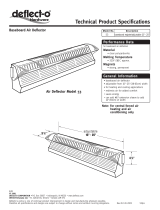
hermostat in right junction box: (Figure B)
1. Cut closed end splice from connection of element lead wire and
return wire (wire behind deflector). Strip 1/2” of insulation from
t
hese two cut lead wires.
a. Join the lead wire from the element with the lead wire from
thermostat terminal J5L2 with a connector.
b. Join the return wire (wire behind deflector) with the lead wire
from thermostat terminal J1T1 with a connector.
2. Connect the grounding lead of the power supply to the supplied
grounding screw.
3. Connect each of the remaining two power supply leads to each lead
from the thermostat rocker switch with a wire connector.
a
. Be sure the panel does not interfere with the mounting of the
thermostat plate. Move panel if needed. (Using a rubber-coated
tool, or hammer handle; carefully pry upwards.)
4. Carefully push wiring back into junction box. Keep all wires away
from the Smart-Base circuit board. These wires may interfere
with the clock and thermostat’s performance. Hook upper edge
of faceplate under lip of case. Lower bottom edge of faceplate to
junction box surface and secure thermostat with mounting screw.
5. Rocker switch should be placed in the “O” (OFF) position. To finish
see the “Completion of Installation” section below.
FIGURE “A” (Left Junction Box Wiring)
FIGURE “B” (Right Junction Box Wiring)
Completion of Installation
At this point, the baseboard should be securely mounted, and the SBFT2
thermostat wired and secured to the baseboard junction box. The other
junction box should have the baseboard end plate/cover secured in place.
Verify that the thermostat rocker switch is in the “O” (OFF) position
before reestablishing the electrical power at the panel for power flow
to the baseboard heater.
Refer to the General Programming Operation Guide for the operation of the
SBFT2 thermostat.
!"++")-2
WARRANTY: Warranties are non-transferable and apply to original consumer
only. Warranty terms are set out below.
LIMITED ONE-YEAR WARRANTY: Cadet will repair or replace any Cadet product,
including thermostats, found to be defective within one year after the date
of purchase.
THESE WARRANTIES DO NOT APPLY:
1. Damage occurs to the product through improper installation or incorrect
supply voltage;
2. Damage occurs to the product through improper maintenance, misuse,
abuse, accident, or alteration;
3. The product is serviced by anyone other than Cadet;
4. If the date of manufacture of the product cannot be determined;
5. If the product is damaged during shipping through no fault of Cadet.
6. CADET’S WARRANTY IS LIMITED TO REPAIR OR REPLACEMENT AS SET OUT
HEREIN. CADET SHALL NOT BE LIABLE FOR DAMAGES SUCH AS PROPERTY
DAMAGE OR FOR CONSEQUENTIAL DAMAGES AND/OR INCIDENTAL
EXPENSES RESULTING FROM BREACH OF THESE WRITTEN WARRANTIES
OR ANY EXPRESS OR IMPLIED WARRANTY.
7. IN THE EVENT CADET ELECTS TO REPLACE ANY PART OF YOUR CADET PRODUCT,
THE REPLACEMENT PARTS ARE SUBJECT TO THE SAME WARRANTIES AS
THE PRODUCT. THE INSTALLATION OF REPLACEMENT PARTS DOES NOT
MODIFY OR EXTEND THE UNDERLYING WARRANTIES. REPLACEMENT OR REPAIR
OF ANY CADET PRODUCT OR PART DOES NOT CREATE ANY NEW WARRANTIES.
8. These warranties give you specific legal rights, and you may also have other
rights which vary from state to state. Cadet neither assumes, nor authorizes
anyone to assume for it, any other obligation or liability in connection with its
products other than as set out herein.
If you believe your Cadet product is defective, please contact Cadet
Manufacturing Co. at 360-693-2505, during the warranty period, for instructions
on how to have the repair or replacement processed. Warranty claims made
after the warranty period has expired will be denied. Products returned
without authorization will be refused.
Parts and Service
Visit http://support.cadetco.com for information on where to obtain parts and
service.
Reduce-Reuse-Recycle
This product is made primarily of recyclable materials. You can
reduce your carbon footprint by recycling this product at the end of
its useful life. Contact your local recycling support center for further
recycling instructions.
©2009 Cadet Manufacturing Co. Printed in U.S.A. 10/11 #720004
See the “General Programming Operation” guide for complete operating instructions. The heater and thermostat must be properly installed before
they are used.
/