Page is loading ...

cadetheat.com Tel: 855.CADET.US PO Box 1675 Vancouver, WA 98668-1675
Benets You Can Depend On
SAVE THESE INSTRUCTIONS
Smart-Base Built-In Thermostat Kit
Installation Instructions
IMPORTANT
http://cadetheat.com/products/thermostats/smart-base
• Controls temperature with a 2-degree
comfort range for up to 28% savings on
your heating bill
• Save energy and time—customize up
to four daily programs, or use the 5-1-1
option to schedule your weekdays and
weekends
• Convenient push-button controls
• Digital display screen makes it easy to see
room temperature, time, and day
• Install on either end of standard Cadet
electric 240- or 208-volt baseboard
heaters
• 12.6 Amps for use with one heater only;
maximum 20 amp circuit
• Double pole (4 wires) with positive o
position
• Setpoint temperature range: 41º - 86ºF
• Your SBFT2 built-in thermostat is guaran-
teed with a 1 year limited warranty
1. Read all instructions before installing or using
this thermostat.
2. High temperatures may be generated under
certain abnormal conditions. Do not partially or
fully cover or obstruct the front of this heater.
3. Do not operate any heater after it malfunctions.
Disconnect power at service panel and have
heater inspected by a qualied electrician before
reusing.
4. To disconnect heater, turn controls to o, and
turn o power to heater circuit at main disconnect
panel.
5. Do not insert or allow foreign objects to enter
any ventilation or exhaust opening as this may
cause an electric shock or re, or damage the
heater.
6. To prevent a possible re, do not block air
intakes or exhaust in any manner.
7. A heater has hot and arcing or sparking parts
inside. Do not use it in areas where gasoline,
paint, or ammable vapors or liquids are used or
stored.
8. Do not use outdoors.
When using electrical appliances, basic precautions should always be followed to reduce the risk of re,
electric shock, and injury to persons, including the following:
TOOLS REQUIRED
• Phillips Screwdriver
• Insulated Wire Connectors
• Wire Strippers
• Wire Cutters
The SBFT2 thermostat must be mounted in the same
wiring compartment as the supplied electrical power to
your Cadet Electric Baseboard. Both wiring compartments
are equipped with a grounding screw.
The installation of the SMART-BASE thermostat may
require a slight adjustment of the panel across the front
of the heater, to allow the thermostat to t in the wiring
compartment unobstructed. To do so, remove both
wiring compartment covers and unlatch the bottom of the
front panel from its hangers. (Use a rubber-coated tool,
or hammer handle to remove the panel. Carefully pry
upward to remove.)
Next, slide the panel out of the wiring compartment with
the supplied electrical power, until its edge is just hanging
over the partition. Hold the panel and snap it back on to
its hangers. The thermostat will now have enough room
to t into the wiring compartment.
Model SBFT2
Page 1

INSTALLATION INSTRUCTIONS
New SBFT2 installation
LEFT
Wiring
Compart
-
ment
Part 2 - Wiring Instructions
Replacing existing BTF thermostat control
Part 1
GROUND
SCREW
GROUND
SUPPLY
Manufacturing Co.
Vancouver, WA
Model: SBFT-2
Volts: 208-240 Vac
Amps: 12.6
Mfg: 01-Feb-13
LISTED BASEBOARD
HEATER ACCESSORY
For use with Model F
Use only or less branch circuit PN070152
DO NOT
DISCONNECT
J5L2
Te rminal
Manufacturing Co.
Vancouver, WA
Model: SBFT-2
Volts: 208-240 Vac
Amps: 12.6
Mfg: 01-Feb-13
LISTED BASEBOARD
HEATER ACCESSORY
For use with Model F
Use only or less branch circuit PN070152
DO NOT
DISCONNECT
J1T1
Te rminal
DO NOT
DISCONNECT
Manufacturin
g Co.
Vancouver,
WA
Model: SBFT-2
Volts: 208-240 Vac
Amps: 12.6
Mfg: 01-Feb-13
LISTED BASEBOARD
HEATER ACCES
SORY
For use with Model F
Use only or less branch circuit PN070152
DO NOT
DISCONNECT
BASEBOARD
ELEMENT
HIGH TEMPERATURE
LIMIT
J1T1
J5L2
CIRCUIT
BOARD
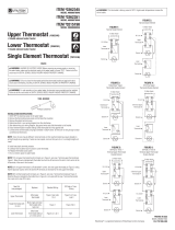
THERMOSTAT INSTALLED IN THE LEFT JUNCTION BOX
L1
L2
ON/OFF
SWITCH
WIRE CONNECTIONS
BASEBOARD
ELEMENT
HIGH TEMPERATURE
LIMIT
J1T1
J5L2
CIRCUIT
BOARD
THERMOSTAT INSTALLED IN THE RIGHT JUNCTION BOX
WIRE CONNECTIONS
L1
L2
ON/OFF
SWITCH
1. All electrical work and materials must comply
with the National Electric Code (NEC), the Occu-
pational Safety and Health Act (OSHA), and all
state and local codes.
2. Use copper conductors only.
3. Turn o power to heater circuit at main discon-
nect panel.
4. Connect grounding lead to grounding screw
provided.
STEP 2
Install the Cadet Electric Baseboard
heater according to the installation
instructions supplied with the product.
The SBFT2 thermostat must be located
in the same wiring compartment as the
supplied electrical power. Both wiring
compartments are equipped with a
grounding screw.
STEP 1
Turn the electrical power o at the
circuit breaker or fuse box.
STEP 3
Remove the wiring compartment
cover at the end of the baseboard
that has the supplied electrical
power.
STEP 4
Connect the supply grounding
wire to the green grounding
screw provided.
STEP 5
Follow the appropriate instructions
in Part 2 for left or right wiring
compartment.
A. Locate and cut closed end
splice containing limit wire
(bottom) and return wire behind
deector (top). Strip 1/2" of
insulation from these two cut
wires.
DO NOT DISCONNECT
THE OTHER CLOSED END
SPLICE!
B. Join the wire from the limit
(bottom) with the wire from
thermostat terminal J5L2 with a
wire connector.
D. Connect each of the
remaining two power supply
leads to each lead from the
thermostat rocker switch
with a wire connector.
Proceed to Part 3.
C. Join the return wire behind
deector (top) with the wire from
thermostat terminal J1T1 with a
wire connector.
STEP 2
Remove screw attaching
the existing BTF assembly
to the baseboard case
and carefully pull it back
to expose the wiring and
connections. (Test with
meter or circuit tester to
verify that no electrical
power is present before
proceeding.)
STEP 3
If the power supply has
been brought into the
baseboard at the wiring
compartment with the
BTF, undo the wire
connectors and remove
the old thermostat.
Proceed to Part 2
for left or right wiring
compartment.
STEP 4
If the power supply has not been brought into the
baseboard at the wiring compartment with the BTF, undo
the wire connectors and remove the old thermostat.
The new SBFT2 must be located in the same wiring
compartment as the supplied electrical power. Strip 1/2”
of insulation from the two wire leads created when the
thermostat was removed. Join the two wires back together
using a wire connector. Remove the wiring compartment
cover from the other end and install it to the wiring
compartment where the thermostat was removed.
Proceed to Part 2 for left or right wiring compartment.
Figure A Figure BWiring Diagram - Left Wiring Diagram - Right
Page 2

RIGHT
Wiring
Compart
-
ment
INSTALLATION INSTRUCTIONS (continued)
Part 3 - Completion of Installation
Warranty
Operating Your Thermostat
Part 2 - Wiring Instructions (continued)
Manufacturing Co.
Vancouver, WA
Model: SBFT-2
Volts: 208-240 Vac
Amps: 12.6
Mfg: 01-Feb-13
LISTED BASEBOARD
HEATER ACCESSORY
For use with Model F
Use only or less branch circuit PN070152
J5L2
Te rminal
Manufacturing Co.
Vancouver, WA
Model: SBFT-2
Volts: 208-240 Vac
Amps: 12.6
Mfg: 01-Feb-13
LISTED BASEBOARD
HEATER ACCESSORY
For use with Model F
Use only or less branch circuit PN070152
J1T1
Te rminal
GROUND
SCREW
Manufacturing Co.
Vancouver, WA
Model: SBFT-2
Volts: 208-240 Vac
Amps: 12.6
Mfg: 01-Feb-13
LISTED BASEBOARD
HEATER ACCESSORY
For use with Model F
Use only or less branch circuit PN070152
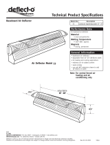
A. Cut closed end splice
from baseboard lead wires.
Strip 1/2" of insulation from
these two cut wires.
B. Join the wire from the
baseboard element (bottom)
with the wire from thermostat
terminal J5L2 with a wire
connector.
D. Connect each of the
remaining two power supply
leads to each lead from the
thermostat rocker switch with a
wire connector.
Proceed to Part 3.
C. Join the wire behind deector
(top) with the wire from thermostat
terminal J1T1 with a wire
connector.
STEP 1
Be sure the panel of the
baseboard does not interfere with
the mounting of the thermostat
plate. Move panel if needed.
(Using a rubber-coated tool,
or hammer handle; carefully
pry upwards.) See page 1 for
complete instructions.
For more eective and safer operation and to prolong the life of the
heater, read the Owner’s Guide and follow the instructions. Failure
to properly maintain the heater will void any warranty and may
cause the heater to function improperly.
LIMITED ONE-YEAR WARRANTY: Cadet will repair or replace
any Smart-Base (SBFT2) thermostat found to be defective within
one year after the date of purchase.
These warranties do not apply:
1. Damage occurs to the product through improper installation or
incorrect supply voltage;
2. Damage occurs to the product through improper maintenance,
misuse, abuse, accident, or alteration;
3. The use of unauthorized accessories or unauthorized compo-
nents constitutes an alteration and voids all warranties. Refer to
Cadet website or call customer service at 855.CADET.US for list
of authorized accessories and components.
4. CADET’S WARRANTY IS LIMITED TO REPAIR OR REPLACE-
MENT.
5. IN THE EVENT CADET ELECTS TO REPLACE ANY PART OF
YOUR CADET PRODUCT, THE REPLACEMENT PARTS ARE
SUBJECT TO THE SAME WARRANTIES AS THE PRODUCT.
THE INSTALLATION OF REPLACEMENT PARTS DOES NOT
MODIFY OR EXTEND THE UNDERLYING WARRANTIES.
REPLACEMENT OR REPAIR OF ANY CADET PRODUCT OR
PART DOES NOT CREATE ANY NEW WARRANTIES.
If you believe your Cadet product is defective, please contact
Cadet during the warranty period, for instructions on how to have
the repair or replacement processed.
Parts and Service
Visit cadetheat.com/parts-service for information on where to
obtain parts and service.
Reduce-Reuse-Recycle
This product is made primarily of recyclable materials.
You can reduce your carbon footprint by recycling this
product at the end of its useful life. Contact your local
recycling support center for further recycling instructions.
STEP 2
Carefully push wiring back into the wiring compartment.
Keep all wires away from the Smart-Base circuit board.
These wires may interfere with the clock and thermostat’s
performance. Hook upper edge of thermostat under lip of case.
Lower the bottom edge of thermostat to wiring compartment
surface and secure with mounting screw.
Be sure all four wire connectors are tight and secure.
STEP 3
At this point, the baseboard should be securely
mounted, and the SBFT2 thermostat wired and
secured to the baseboard junction box. The
other junction box should have the baseboard
end plate/cover secured in place.
Verify that the thermostat rocker switch is in the
“O” (OFF) position before reestablishing the
electrical power at the panel for power ow to
the baseboard heater.
This thermostat will load its default settings after power is established for the rst time.
Refer to the General Programming Operation Guide included for complete programming and operating instructions of
your SBFT2 thermostat.
The heater and thermostat must be properly installed before they are used.
©2016 Cadet Printed in USA Rev 11/16 #720004
Page 3
/