Page is loading ...

DIGITAL TACHOMETER
ATE-6036
User’s Manual
www.tmatlantic.com

www.tmatlantic.com
2
Ⅰ FEATURES
1. It is used the microcomputer (CPU) technique and junction laser technique for one instrument combine PHOTO TACH. (RPM)
&CONTACT TACH (RPM, m/min).
2. Wide measuring range and high resolution.
3. Yellow green backlight makes sure that tachometer can work normally in any light circumstance.
4. The last displayed value/max. Value/min. Value maybe automatically stored in memory and 96s of measured value continuously. So this
makes customers collected and recorded data. (The tachometer starts to store the data measured after which is renovation for three
times).
5. The tachometer can be connected 6V direct current stable voltage power in favor of using for long time.
6. Low battery voltage indication.
7. Contact part and photo part can be switched value at any time.
8. New surface speed sensor with flute vials to measure speed and length of wire, cable and rope conveniently.
9. The instrument is delicate and rugged. It uses the durable, long-lasting components and a strong, light weight ABC plastic housing. The
comfortably in either hand.
ⅡSPECIFICATION
1. Display: 5digital, 18mm (0.7” yellow green backlight LCD)
Accuracy: ±(0.05%+1digital)
Sampling Time: 0.8second (over 60RPM)
Range Select: Auto-range
Time Base: Quartz crystal
Detecting Distance: 50mm-500mm (photo)
Dimension: 210×74×37mm
Power: 4×1.5V AA size battery or 6V direct current stable voltage power.
Power consumption: approx. 65mA
2. Memory call button operation A readout (the max value, min value, last value) obtained immediately before turning off the MEATURING
BUTTON is automatically memorized. For example, please ret. following figure 1. That memorized value can be displayed on the indicator
by turn once depressing the memory button. The symbol “UP” represents the MAX. Value and “DN” the MIN. Value, “LA” the Last Value.
3. Battery replacement
When it is necessary to replace the battery(battery voltage less tan approx.4.5V), will appear on the display.
Slide the battery cover away from the instrument and remove the battery.
Install the batteries into the case permanent damage to the circuit may result form incorrect installation.
4. Reminds
5.1 Reflective mark: cut and peel adhesive tape provided into approx. 12mm (0.5”) squares and apply one square to each rotation shaft. The
non-reflective area must always be greater than the reflective area. If the shaft is normally reflective, it must be covered with black tape or
black paint before attaching reflective tape. Shaft surface must be clean and smooth before applying reflective tape.
5.2 Very low RPM measurement: as if is easy to get high resolution. If measuring the very low RPM values, suggest user to attach more
“reflective marks” averagely. Then divide the reading shown by the number of “reflective marks” to get the real RPM.
5.3 Contact tachometer parts include large taper, small taper and pillar, large taper and pillar rubberpart is suitable to low speed and but the small
high speed.
5.4 If the instrument is not to be used for any extended period, remove batteries.
Ⅲ PHOTO TACHOMETER:
Measuring Range: 2.5 to 99999RMP
Resolution: 0.1RPM (2.5 to 999.9RMP)
1RPM (over 1000RPM)
Total Test Range: 1 to 99999
CONTACT TACHOMETER:
Measuring Range: CONTACT THCH 0.5 to 19999RPM
Surface Speed (m/min): 0.05 to 1999.9m/min
Surface long (m): 0.05 to 99999m
Resolution: CONTACT THCH: 0.1RPM (0.5 to 999.9RPM)
1RPM (over 1000RPM)
Surface Speed: 0.01m/min (0.05 to 99.99m/min)
0.1m/min (over 100m/min)
Surface long: 0.02m (0.05 to 99999m)

www.tmatlantic.com
3
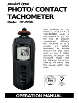
Panel description:
A: Reflective mark
B: Signal light beam
C: Measure button
D: Function switch
E: Memory call button
F: Display window
G: Battery cover
Measuring procedure
1. PHOTO RPM MEASUREMENT
a. Apply a reflective mark to the object being measured. Slide the function switch to “ RPM” position.
b. Depress the MEASURE BUTTON and align the visible light beam with the applied target. Verify
that the MONITOR INDICATION lights when the target aligns with the beam.
2. TOTAL MEASUREMENT
a. Apply a reflective mark to the object being measured. Slide the function switch to “TOT” position.
b. Install the batteries and press measuring button, then you see light beam line with the target, start
measuring. The value will add 1 as the object rotate a circle or passed one reflective mark, herein,
the total value will stored in the meter until loosen the button.
c. It will display total value as you press “MEM” button.
Accessories:
Carrying case 1pc
Reflecting tape marks length 600mm
Operation manual 1pc
Damproof accessories 1pc
Bolt bag 1pc
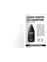
ⅣPanel description:
A: surface speed wheel
B: RPM adapter
C: shaft
D: measure button
E: function switch
F: memory call button
G: display window
H: battery cover
Measuring procedure
1. CONTACT TACH MEASUREMENT
a. Slide the FUNCTION SWITCH to “rpm” position. Install the proper RPM ADAPTER on
the SHAFT.
b. Depress the MEASUING BUTTON and lightly pressing the RPM ADAPTER against the
center hole of rotating shaft. Be certain to keep alignment straight. Release the
MEASURING BUTTON when the display reading stabilizes.
2. SURFACE SPEED MEASURENENT
a. Slide the FUNCTION SWITCH to “m/min”, in stall the SURFACE SPEED WHEEL on the SHAFT instead of the RPM ADAPTER.
b. Depress the MEASURING BUTTON and simply attaching the SURFACE SPEED WHEEL to the detector. Release the MEASURING
BUTTON when the display reading stabilizes.
3. SURFACE LONG MEASUREMENT
a. Slide the FUNCTION SWITCH to “m” and use the corresponding part. The other same as (2).
Note: Because of the difference between the girth of outer surface and inner flute of line speed sensor. For contact line speed or length
measurement. The displaying result is correct when outer surface of the sensor contacts with the measured object contact and but when inner
flute of the sensor and the measured object, that the reading multiply 0.9is the real result (eg.: measure wire, cable and rope etc.)

www.tmatlantic.com
4
Accessories:
Carrying case 1pc
Operation manual 1pc
Damproof accessories 1pc
Bolt bag 1pc
Contact speed measurement fitting 1pc
Contact rotational speed measurement fitting 3pc
Ⅴ PHOTO TACH/CONTACT TACH
Measuring Range: PHOTO TACH
to 99999RPM
CONTACT TACH
0.5 to 19999RPM
SURFACE SPEED (m/min)
0.05 to 1999.9m/min
Resolution: PHOTO TACH:
0.1RPM (2.5 to 999.9RPM)
1RPM (over 1000RPM)
CONTACT TCAH
0.1RPM (0.5to 999.9RPM)
1RPM ( over 1000RPM)
WURFACE SPEED
0.01m/min (0.05 to 99.99m/min)
0.1m/min (over 100m/min)
Panel description:
A: Surface speed wheel
B: Contact test device
C: Contact measuring device
D: Measure button
E: Function switch
F: Memory call button
G: Display window
H: Battery cover
Measuring procedure
1. PHOTO MEASURMNENT
a. Apply a reflective mark to the object being measured. Slide the function switch to “rpm
photo” position.
b. Depress the MEASURE BUTTON and align the visible light beam with the applied
target. Verify that the MONITOR INDICATOR lights when the target aligns with the
beam.
2. CONTACT TACH MEASUREMENT
a. Slide the FUNCTION SWITCH to “rpm contact” position. Install the proper RPM
ADAPTER on the SHAFT.
b. Depress the MEASURING BUTTON and lightly pressing the RPM ADAPTER
against the center hole of rotating shaft. Be certain to keep alignment straight. Release
the MEASURING BUTTON when the display reading stabilizes.
3. SURFACE SPEED MEASUREMENT
a. Slide the FUNCTION SWITCH to “m/min contact” position. Install the SURFACE SPEED WHEEL on the SHAFT instead of the RPM
ADAPTER.
b. Depress the MEASURING BUTTON and simply attaching the SURFACE SPEED WHEEL to the detector. Release the MEASURING
BUTTON when the display reading stabilizes.
Note: Because of the difference between the girth of outer surface and inner flute of line speed sensor. For contact line speed or length
measurement, the displaying result is correct when outer surface of the sensor contacts with the measured object contact and but when inner flute
of the sensor and the measured object, that the reading multiply 0.9 is the real result (eg.: measure wire, cable and rope etc.)

www.tmatlantic.com
5
Accessories:
Carrying case 1pc
Reflecting tape marks length 600mm
Operation manual 1pc
Damproof accessories 1pc
Bolt bag 1pc
Contact speed measurement fitting 1pc
Contact rotational speed measurement fitting 3pc
/