Page is loading ...

INSTALLATION INSTRUCTIONS
FOR EBF-625/EBF-655
SENSOR ACTIVATED FAUCETS
Code No: 9108237
Rev. 3 (12/10)
O P T I M A F A U C E T S
MODELS
EBF-625
EBF-655
Battery Powered,
Sensor Activated
Lavatory Faucets
EBF-625
EBF-655
Installation of the Sloan Optima Plus EBF-625 or EBF-655 Battery
Powered, Sensor Activated Faucet makes wash-up totally “hands free”
providing the ultimate in sanitary protection and automatic operation.
The Optima Plus faucet uses infrared technology to sense the user’s
presence and turn on a water supply that has been pre-mixed to the
desired water temperature. When the user’s hands are removed from
the invisible beam of light, the water supply automatically turns off.
In addition, the faucet is powered by four (4) “C” batteries which
eliminates the need to run any electrical lines to the system.
The Sloan EBF-625 or EBF-655 battery powered, sensor activated
faucet comes complete with an integral faucet and sensor assembly,
control module, alkaline batteries, and all mounting hardware.
Bak-cheks and a grid strainer are also available as optional equipment.
The installer should supply 3/8” copper supply tube or exible hose
connections.
The following instructions serve as a guide when installing the Sloan
EBF-625 or EBF-655 faucet. As always, good safety practices and care
when installing your new faucet.
If further assistance is required, contact your nearest
Sloan Representative ofce or the Sloan Installation
Engineering Department at 1-888-SLOAN-14.
LIMITED WARRANTY
Sloan Valve Company warrants its EBF-625 and EBF-655 faucets to be made of rst class materials, free from defects of material or workmanship under normal
use and to perform the service for which they are intended in a thoroughly reliable and efcient manner when properly installed and serviced, for a period of
three (3) years (one (1) year for special nishes) from date of purchase. During this period, Sloan Valve Company will, at its option, repair or replace any part or
parts which prove to be thus defective if returned to Sloan Valve Company, at customer’s cost, and this shall be the sole remedy available under this warranty.
No claims will be allowed for labor, transportation or other incidental costs. This warranty extends only to persons or organizations who purchase Sloan Valve
Company’s products directly from Sloan Valve Company for purpose of resale. This warranty does not cover the life of batteries.
THERE ARE NO WARRANTIES WHICH EXTEND BEYOND THE DESCRIPTION ON THE FACE HEREOF. IN NO EVENT IS SLOAN VALVE COMPANY RESPONSIBLE FOR ANY
CONSEQUENTIAL DAMAGES OF ANY MEASURE WHATSOEVER.

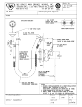
ROUGH-INS
SPOUT
WING NUT AND
SLOTTEDWASHER
BASE GASKET
†
‡
† ‡
1/8" NPT PIPE TO 3/8" TUBE
COMPRESSION FITTING
1/8" PIPE NIPPLE
3/8" COMPRESSION
FITTING
3/8" COMPRESSION FITTING
3/8" COPPER SUPPLY
TUBE (NOT SUPPLIED)
3/8" COPPER
SUPPLY TUBES
(NOT SUPPLIED)
SOLENOID VALVE
EBF-655 FAUCETWITHDUAL LINE WATER SUPPLY
1" (25 mm)minimumdiameter hole required to mount faucet shank on deck.
3/8" (10 mm)minimumdiameter clearance for mounting studs.
3/8" COMPRESSION STOPS (NOT SUPPLIED)
BAK CHEK
3/8" COMPRESSION TEE
3/8" COPPER SUPPLY
TUBE (NOT SUPPLIED)
CONTROL MODULE
3/8" COMPRESSION STOP OR
MIXING VALVE (NOT SUPPLIED)
SPOUT
WING NUT AND
SLOTTED WASHER
CONTROL MODULE
BASE GASKET
1/8" NPT PIPETO3/8" TUBE
COMPRESSION FITTING
1/8" PIPE NIPPLE
3/8" COMPRESSION
FITTING
3/8" COMPRESSION FITTING
3/8" COPPER SUPPLY
TUBE (NOT SUPPLIED)
3/8" COPPER
SUPPLY TUBE
(NOT SUPPLIED)
SOLENOIDVALVE
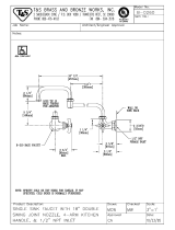
EBF-655FAUCETWITHSINGLE LINE WATER SUPPLY
† ‡
EBF-625 FAUCET WITH SINGLE LINE WATER SUPPLY
3/8" COMPRESSION STOP OR
MIXING VALVE (NOT SUPPLIED)
SPOUT
W
ING NUT AND
SLOTTED WASHER
1
/4" NPT PIPETO3/8" TUBE
COMPRESSION FITTING
SPACER, FLAT WASHER,
LOCK WASHER AND NUT
3/8" COMPRESSION
F
ITTING
3/8" COMPRESSION FITTING
CONTROL MODULE
3/8" COPPER SUPPLY
TUBE (NOT SUPPLIED)
3/8" COPPER
SUPPLY TUBE
(NOT SUPPLIED)
SOLENOIDVALVE
BASE GASKET
EBF-625 FAUCET WITH DUAL LINE WATER SUPPLY
1/4" NPT PIPE TO 3/8" TUBE
C
OMPRESSION FITTING
SPACER, FLAT WASHER,
LOCK WASHER AND NUT
3
/8" COMPRESSION
FITTING
3
/8" COMPRESSION FITTING
3
/8" COPPER SUPPLY
TUBE (NOT SUPPLIED)
3
/8" COPPER
S
UPPLY TUBES
(NOT SUPPLIED)
SOLENOID VALVE
3/8" COPPER SUPPLY
TUBE (NOT SUPPLIED)
CONTROL MODULE
BASE GASKET
S
POUT
3/8" COMPRESSION STOPS (NOT SUPPLIED)
BAK CHEK
3/8" COMPRESSION TEE

ROUGH-INS (CONTINUED)
EBF-625 FAUCETWITHBOTH DUAL AND SINGLE LINE WATER SUPPLIES
TOTAL LENGTH OF
SENSOR CABLE IS
24" (610 mm)
3-1/2"
(
89 mm)
2-1/2"
(
64 mm)
2
-3/4" (70 mm)
5-1/4"
(133 mm)
3/4" (19 mm)
2
" (51mm)
1
-1/4" (32 mm)
1
2
o
4-1/2"
(114 mm)
3-1/2" (89 mm)
EBF-655 FAUCETWITHBOTH DUAL AND SINGLE LINE WATER SUPPLIES
TOTAL LENGTH OF
SENSOR CABLE IS
23" (584 mm)
3-1/2"
(
89 mm)
2-1/2"
(
64 mm)
2
-3/4" (70 mm)
5-1/4"
(
133 mm)
3/4" (19 mm)
2
" (51 mm)
1-1/4" (32 mm)
1
2
o
4-1/2"
(114 mm)
3-1/2" (89 mm)
PRIOR TO INSTALLATION
Prior to installing the Sloan EBF-625 or EBF-655 faucet, install the items listed
below.
• Lavatory/Sink
• Drain Line
• Hot Water and Cold Water OR Tempered Water Supply Lines
IMPORTANT:
•
ALL PLUMBING IS TO BE INSSTALLED IN ACCORDANCE WITH
APPLICABLE CODES AND REGULATIONS
•
FLUSH ALL WATER LINES PRIOR TO MAKING CONNECTIONS
MIXING VALVE
When installation includes one of Sloan’s Mixing Valve, these instructions AND
those included with the mixing valve MUST be followed.
The Sloan EBF-625 and EBF-655 battery powered sensor activated faucets can
be supplied with two Bak-Cheks. When connecting the faucet to a hot and cold
water supply, two Bak-Cheks are required. Water temperature can be con-
trolled by adjusting the supply stops. When connecting the faucet to a single
line water supply or a pre-tempered water supply, a Bak-Chek is not required.
1 - INSTALL BAK-CHEK TEE (OPTIONAL)
The Sloan Bak-Chek is designed for installation on a 3/8” supply stop.
If an existing stop is used, the stop may require replacement or additional
ttings not supplied by Sloan for connection of the Bak-Chek to the hot
and cold water supply lines. Supply stops should be furnished by the
installer.
After ushing the water supply lines through the stops, use a
compression nut and compression sleeve to connect inlet end of
Bak-Chek to the Supply Stop.
NOTE:
Failure to install the Bak-Chek can result in a cross ow
connection when the faucet is in the off position and the supply stops
are open. If the pressures of the hot water supply and the cold water
supply are different, hot water can migrate into the cold water supply
or cold water can migrate into the hot water supply. Most plumbing
codes require that the Bak-Chek be used to prevent this occurance.
A
B
3/8” (10 mm)
BAK-CHEK TEE
3/8” (10 mm)
SUPPLY TUBE
3/8” (10 mm)
COMPRESSION FITTING

2A - INSTALL EBF-625 FAUCET
NOTE:
Sloan Valve Company reccomends that this faucet is installed
with our trim plate. Our trim plate includes an anti-rotation feature to
prevent rotary motion of this single-hole pedestal-style faucet.
Slide faucet base gasket over faucet shank and sensor cable.
Install optional trim plate next followed by the trim plate gasket. Holding
the faucet base gasket and optional trim plate assembly in place, insert
sensor cable and faucet shank through the 1” (25 mm) center hole in
d
eck lavatory. Use plumber’s putty to secure optional trim plate.
Thread sensor cable through side of mounting spacer, and then secure
faucet to deck or lavatory using the mounting washer, lock washer and
nut. Apply thread sealant or Teon tape to threads at end of faucet
shank.
2B - INSTALL EBF-655 FAUCET
NOTE:
Refer to the Installation Instructions included
with the ETF-578-A trim plate for addtional information
about using an 8” trim plate with an EBF-655 faucet.
Slide faucet base gasket onto faucet.
Insert faucet sensor cable, pipe nipple, and mounting studs through the
4” (102 mm) spread deck holes. Secure faucet to deck using slotted
mounting washers and wing nuts supplied.
3 - MOUNT CONTROL MODULE TO WALL
IMPORTANT: DO NOT
install control module upside down. The
control module may be oriented so that it faces sideways (vertically);
however, optimum performance is obtained when the control module is
horizontal with the Sloan logo on the cover facing up.
Install the control module in an appropriate location. All four (4) cover
screws must be accessible from the chosen mounting position. After
installation, the cable from spout to control module should have
some slack.
Remove control module cover from control module base. Use the control
module base as a template to mark locations on wall for mounting
fasteners. Determine the appropriate mounting fastener for the particular
wall type (three different fastener types are included; see parts list). Drill
four (4) appropriately sized holes.
For plastic wall anchor – 1/4” (6 mm) holes
For hollow wall anchor – 5/16” (8 mm) holes
For toggle nut anchor – 3/8” (10 mm) holes
Install 3/8” compression tting on end of faucet shank.
FAUCET
BASE GASKET
FAUCETSENSOR
C
ABLE
1
/4" NPT PIPE
NIPPLE
1/4" NPT PIPETO3/8"
T
UBE COMPRESSION
FITTING
M
OUNTING
SPACER
F
LAT WASHER
LOCKWASHER
MOUNTING NUT
FAUCET
SLOTTED MOUNTING
WASHERS(2)
WINGNUTS (2)
MOUNTING STUDS
FAUCET SENSOR
CABLE
1/8" NPTPIPE
NIPPLE
BASE GASKET
A
B
C
D
A
B
A
B
C
Attach Control Module base to wall using appropriate fastener.
DRILL FOUR HOLESINTOWALL
USING MOUNTINGFASTENERS
APPROPRIATE FOR THE
PARTICULAR WALL TYPE:
•PLASTIC WALL ANCHOR—
1/4" (6 mm)HOLE
•HOLLOWWALL ANCHOR—
5/16" (8 mm)HOLE
• TOGGLE NUT ANCHOR—
3/8" (10 mm)HOLE
CONTROL
MODULE
WALL
PLASTIC ANCHOR
WITH SCREW AND
WASHER SHOWN
3-1/2"
(89mm)
4-3/8"
(111 mm)

4 - CONNECT SENSOR CABLE TO CONTROL MODULE
Remove circuit board cover from control module.
Route sensor cable from spout to the control module, usually located
under the faucet with sufcient slack in sensor cable. Insert locking
connector from faucet spout into mating receptacle on connector board
of control module.
Insert the sensor cable into the strian relief slot in the control module.
Install circuit board cover into control module.
5 - CONNECT SUPPLY LINE FROM SOLENOID VALVE OUTLET TO FAUCET
FOR MODEL EBF-625
– Install the 1/4” (6.4 mm) pipe to the 3/8”
(9.5 mm) tube compression tting on spout’s pipe nipple.
FOR MODEL EBF-655
– Install the 1/8” (3.2 mm) pipe to the 3/8”
(9.5 mm) tube compression tting on spout’s pipe nipple.
FOR MODELS EBF-625 AND EBF-655
– Connect 3/8” (9.5 mm) outside
diameter (O.D.) of supply tube (furnished by installer) between the
compression tting on the spout’s pipe nipple and the top outlet
compression tting on the solenoid valve.
A
B
C
D
A
B
1/4" NPT PIPE
TO 3/8’’ TUBE
COMPRESSION
FITTING
1/4" PIPE NIPPLE
3/8" SUPPLY TUBE
(NOT SUPPLIED)
SOLENOID
VALVE
3/8" TEE COMPRESSION
FITTING
3/8" SUPPLY TUBE
(NOT SUPPLIED)
3/8" SOLENOID VALVE
COMPRESSION FITTING
(TOP OUTLET)
3/8" SOLENOID VALVE
COMPRESSION FITTING
(BOTTOM INLET)
1
/8" PIPE TO 3/8"
TUBECOMPRESSION
FITTING
1/8" PIPE NIPPLE
3/8" SUPPLY TUBE
(NOT SUPPLIED)
SOLENOID
VALVE
3/8" TEE COMPRESSION
FITTING
3/8" SUPPLY TUBE
(NOT SUPPLIED)
3/8" SOLENOID VALVE
COMPRESSION FITTING
(TOP OUTLET)
3/8" SOLENOID VALVE
COMPRESSION FITTING
(BOTTOM INLET)
6 - CONNECT SUPPLY LINE(S) FROM SUPPLY STOP TO SOLENOID VALVE INLET
NOTE:
Supply stops should be furnished by installer.
Flush dirt, debris, and sediment from the supply line(s).
FOR DUAL LINE HOT AND COLD WATER SUPPLY APPLICATIONS
–
When connecting the faucet to a hot and cold water supply, a Bak-Chek
is required as described in Step 1. If Bak-Chek is not installed at this
time, install them now referring back to Step 1 for instructions.
Install a 3/8” copper supply tube between Bak-Chek Compression Tee
Fitting supplied.
Install a 3/8” copper supply tube between compression tee tting and the
bottom inlet compression tting of solenoid valve.
FOR SINGLE LINE WATER SUPPLY APPLICATIONS
– When connecting the
faucet to a single line water supply or a pre-tempered water supply, no
Bak-Chek is required.
Install a 3/8” copper supply tube between the supply stop and the bottom
inlet compression tting of solenoid valve.
A
B
C
NOTE:
An arrow on the body of the solenoid valve
indicates the water ow direction.
IMPORTANT:
Keep thread sealant out of your waterway and
prevent component part damage!
DO NOT USE
sealant on
compression ttings. When thread sealant is used,
DO NOT APPLY
it to the rst two “starter” threads.

7 - INSTALL BATTERIES
Remove the battery compartment from the control module by gently pulling
straight out. Spread the ends of the battery retainer and remove it from the
battery compartment. Insert the four (4) “C” cell alkaline batteries provided as
indicated by the (+) and (-) symbols inside the battery compartment. Spread the
e
nds of the battery retainer and slide it over the battery compartment until
locked into place.
NOTE:
Battery retainer must be installed, shown right.
If installed upside-down, it will not install into the control
module. Reinsert the battery compartment into the control
m
odule. See image, shown right.
8 - START-UP
Open supply stops. Remove spray head, then activate faucet for 30
seconds by placing hands in front of the sensor. The solenoid valve
should “click,” sensor LED indicator should blink and water should ow
from the spout. If this does not occur, refer to the Troubleshooting
section.
NOTE:
The sensor LED indicator should blink when faucet is
activated for the rst 10 minutes after start-up.
Close supply stop(s) and install spray head in spout using the key
provided. Reopen supply stop(s), activate faucet and check for leaks.
9 - RANGE ADJUSTMENT
The OPTIMA Plus EBF-625 and EBF-655 faucets are factory set to
operate when hands are placed 4-5” (102-127 mm) from sensor. This
range should be satisfactory for most installations.
If range adjustment is required, use a small Phillips screwdriver.
ADJUST RANGE
– The range potentiometer is located in the control
module. Cycle faucet several times to assure that the sensor range does
not inadvertently pick up reection off the edge of the sink. If reection
occurs, slighly adjust range potentiometer counterclockwise and again
cycle faucet.
Repeat adjustment procedure until desired range is achieved.
IMPORTANT:
Range potentiometer adjustment screw rotates only 3/4 of
a turn; DO NOT over-rotate.
10 - INSTALL COVER TO CONTROL MODULE
Place cover over the control module and use the four (4) screws
provided to attach it. Cover can be installed in only one orientation.
IMPORTANT:
Install ALL four (4) cover screws for proper installation.
INSTALL FOUR “C” CELL BATTERIESAS
INDICATED BY THE (+) AND (-) SYMBOLS
AT BOTTOM OF BATTERY COMPARTMENT.
INSTALL BATTERY RETAINER.THEN
I
NSTALL BATTERY COMPARTMENT
I
NTO CONTROL MODULE
AS SHOWN
BATTERY
COMPARTMENT
BATTERY
COMPARTMENT
CONTROL
MODULE
BATTERY
RETAINER
A
B
A
B
C
CONTROL
MODULE
INSTALLCOVERAND
SECURE WITH THEFOUR
(4)COVER SCREWS
IMPORTANT: ALL FOUR (4)COVER
SCREWS MUSTBEINSTALLED
RANGE
POTENTIOMETER
(BENEATH COVER)
CONTROL MODULE

BATTERY REPLACEMENT
The Sloan Optima Plus EBF-625 and EBF-655 battery powered, sensor activated
lavatory faucets are furnished with four (4) “C” cell alkaline batteries that provide up to
two (2) years of operation (8000 cycles per month). A ashing LED signal indicates that
battery power will be depleted within one (1) month. Replace batteries with four (4)
new “C” cell alkaline batteries.
Remove the Cover of the Control Module by unscrewing the four (4) cover screws lo-
cated at the center of each side.
Remove the battery compartment from the control module by gently pulling straight out
with a rm grip. Spread the ends of the battery reainer and remove it from the battery
compartment. Remove the old batteries and insert four(4) fresh “C” cell alkaline
batteries into the battery compartment. Spread the ends of the battery retainer and
slide it over the battery compartment until locked into place.
NOTE:
Battery Retainer MUST be installed as shown. If installed upside-down, it will
not install into the Control Module. Reinsert the Battery Compartment into the Control
Module as shown.
Place cover over the Control Module and use the four (4) screws provided to attach it.
Cover can be installed in only one orientation.
IMPORTANT:
Install ALL four (4) cover screws for proper installation.
CLEANING SCREEN FILTER
Before cleaning the screen lter, turn off water supply at the supply stop(s).
Activate the faucet to relieve any pressure in the system. Unscrew the lter plug
and remove it from the solenoid valve housing. Carefully pull the screen lter
with attached rubber seals out from the solenoid valve housing.
Clean the screen lter using fresh tap water only. If necessary, use a small
brush to clean. Use caution while cleaning to prevent damage to the solenoid
screen lter. If any lter components are damaged, order Filter Replacement Kit
EBF-1004-A.
Carefully replace the screen lter into the groove of the solenoid valve housing.
Examine the lter plug o-ring for wear or damage; replace if necessary. If nec-
essary, lubricate the lter plug o-ring with water to keep it in place in the groove
of the lter plug. Screw the lter plug into the solenoid valve housing.
Turn on the water supply at the supply stop(s). Activate the faucet to purge any
air from the system lines. Check for leaks and repair as necessary.
OPERATION
1
. A continuous
invisible beam of
infrared light is
emitted from the
sensor located on the
throat of the lavatory
faucet.
2
. As the user’s hands
enter the beam’s
effective range (be-
neath the spray
head), the beam is
reected back into
the sensor receiver
and activates the so-
lenoid valve. Tempered water ows from the
f
aucet into the sink until the hands are
removed from the beam or until the faucet
reaches an automatic time out limit setting.
3
. When hands are
moved away from
the sensor, the loss
of reected light
initiates an electrical
signal that
deactivates the
solenoid valve, shut-
ting off the water ow. The circuit then auto-
m
atically resets and is ready for the next user.
MAINTENANCE
CARE AND CLEANING
DO NOT USE
abrasive or chemical cleaners (including chlorine bleach) to clean faucets that may dull the luster and attack the chrome or special decorative nishes.
Use
ONLY
soap and water, then wipe dry with clean cloth or towel. Protect the faucet from any splattering of cleaner when cleaning bathoom tile. Acids and
cleaning uids will discolor or remove chrome plating.
INSTALL FOUR “C” CELL BATTERIESAS
INDICATED BY THE (+) AND (-) SYMBOLS
A
T BOTTOM OF BATTERY COMPARTMENT.
INSTALL BATTERY RETAINER.THEN
INSTALL BATTERY COMPARTMENT
I
NTO CONTROL MODULE
AS SHOWN
BATTERY
COMPARTMENT
BATTERY
COMPARTMENT
CONTROL
M
ODULE
B
ATTERY
RETAINER
SOLENOID
VALVE
HOUSING
SCREEN FILTER
FILTER PLUG
WITHO-RING
IF FILTER COMPONENTSARE
DAMAGED, ORDER FILTER
REPLACEMENT KIT EBF-1004-A
TROUBLESHOOTING GUIDE
1. Faucet does not stop delivering water or continues to drip after user
is no longer detected (automatic shut-off fails even when batteries
are removed.
Solenoid valve has been connected backward.
Disassemble solenoid valve compression ttings at both the inlet
and outlet positions. The water should ow from inlet through the
solenoid valve ot the outlet according to the direction of the arrow
shown on the side of the solenoid valve. Reconnect the
compression ttings in the correct orientation.
Solenoid valve is dirty.
Backush by reversing water ow (opposite to the direction shown
by the arrow on the side of the solenoid valve) through the solenoid
valve. Reconnect the compression ttings in the correct orientation.
Activate faucet.
Solenoid valve module is defective.
Replace EBF-1011-A Solenoid Valve Module.

PARTS LIST
ITEM PART DESCRIPTION
NO. NO.
1A EBF-120-A Pedestal Faucet Spout and Sensor Assembly
(EBF-625)
1B EBF-81-A Faucet Spout and Sensor Assembly (EBF-655)
2 ETF-1023-A 0.5 gpm (1.9 Lpm) Spray Head with Key
ETF-1024-A 2.2 gpm (8.3 Lpm) Aerator Spray Head with Key
F-175-L 2.2 gpm (8.3 Lpm) Laminar Flow Spray Head
3 ETF-435 Replacement Key ONLY for ETF-1023-A and
ETF-1024-A
4A EBF-123-A Faucet Mounting Kit for EBF-625
4B ETF-546-A Faucet Mounting Kit for EBF-655
5A ETF-547 1/8” NPT Pipe to 3/8” Tube Compression Fitting
Connection
5B ETF-617 3/8” Bak-Chek Tee Compression Fitting
5C EBF-113-A Single Solenoid Supply Kit
6 EBF-60-A Control Module Assembly
7 EBF-79-A Mounting Hardware Kit for Control Module Assembly
8A ETF-103-A 4” (102 mm) Centerset Trim Plate for EBF-625
8B MIX-101-A 4” (102 mm) Centerset Trim Plate for EBF-625 with
Optional Mixing Valve
8C ETF-105-A 8” (204 mm) Centerset Trim Plate for EBF-625
8D MIX-106-A 8” (204 mm) Centerset Trim Plate for EBF-625
8E ETF-576-A 8” (204 mm) Centerset Trim Plate for EBF-655
8F ETF-577-A 8” (204 mm) Centerset Trim Plate for EBF-655 with
Optional Mixing Valve
– EBF-80-A Sensor Replacement Kit
– EBF-1011-A Solenoid Replacement Kit
– EBF-1004-A Solenoid Filter Replacement Kit (includes Filter Screen
and O-Ring)
NOTE:
The information contained in this document is subject to change
without notice.
SLOAN VALVE COMPANY • 10500 SEYMOUR AVENUE • FRANKLIN PARK, IL 60131
Phone: 1-800-9-VALVE-9 or 1-847-671-4300 • Fax: 1-800-447-8329 or 1-847-671-4380 • www.sloanvalve.com
Copyright © 2010 SLOAN VALVE COMPANY Code No: 9108237 – Rev. 3 (12/10)
1A
2
4A
7
3
5B
6
5A
8A
3
1B
2
4B
5C
5C
8B
8C
8E
8D
8F
If further assistance is required, please contact the
Sloan Valve Company Installation Engineerying Department
at 1-888-SLOAN-14.
TROUBLESHOOTING GUIDE (CONTINUED)
2. Sensor troubleshooting LED does not function (red indicator light
does not ash during set-up procedure)
No battery power is being supplied to sensor.
Ensure that the batteries are installed properly. Check that the
o
rientation of each battery matches the positive (+) and negative (-)
symbols shown on the bottom of the battery compartment.
Reinsert the battery compartment into the control module.
Insufcient battery power is being supplied to sensor.
One (or more) of the batteries is “dead.” To ensure proper
operation, insert four (4) new “C” sized alkaline batteries. Check
that the orientation of each battery matches the positive (+) and
negative (-) symbols shown on the bottom of the battery
compartment. Reinsert the battery compartment into the
control module.
Sensor Cable is not properly inserted.
Disconnect and reconnect Sensor Cable to the Control Module.
Sensor Range is set at minimum distance.
Increase Sensor Range. Use a small screwdriver to turn the
potentiometer screw (white screw in blue base) clockwise.
Control Module assembly is defective.
Replace EBF-60-A Control Module assembly.
3. The water temperature is too hot or too cold on a faucet connected
to hot and cold supply lines with Bak-Chek.
Supply stops are not adjusted properly.
Adjust Supply Stops.
NOTE:
A thermostatic mixing valve may be required on some systems.
4. Faucet does not deliver any water when Sensor is
activated.
Solenoid valve produces audible “CLICK.” Water supply valve is
closed.
O
pen the water supply.
Solenoid valve DOES NOT produce an audible “CLICK”.
Disconnect and reconnect Solenoid lead to the Control module, if
solenoid lead is not properly connected to the Control Module.
Batteries are not installed properly. Check that the orientation of
each battery matches the positive (+) and negative (-) symbols
shown on the bottom of the battery compartment. Reinsert the
Battery Compartment into the Control Module. The troubleshooting
LED should ash RED when a user is detected.
5. Faucet delivers only a slow ow or dribble when Sensor
is activated.
Water supply valve is partially closed.
Completely open the Supply Stop.
Solenoid Filter is clogged.
Remove, clean, and reinsert. Replace EBF-1004-A Solenoid Filter
Kit, if necessary.
Aerator or Spray Head is clogged.
Remove, clean, and reinsert.
/