Page is loading ...

“ACCUMIX MT”
ELECTRIC INSTANTANEOUS WATER HEATER
WITH ASSE 1070 APPROVED MIXING VALVE
INSTALLATION GUIDE AND OWNERS MANUAL
WARNING
BEFORE ATTEMPTING INSTALLATION OF THIS UNIT OR MAKING ANY
ADJUSTMENTS TO THE UNIT, ALWAYS BE SURE CIRCUIT BREAKER IS OFF
TO PREVENT DANGER OF SERIOUS ELECTRIC SHOCK.
FAILURE TO GROUND THE SYSTEM MAY RESULT IN SERIOUS INJURY OR DEATH
INSTALLER/ CONSUMER RESPONSIBILITIES
READ THIS MANUAL CAREFULLY BEFORE ATTEMPTING TO INSTALL OR
OPERATE THIS WATER HEATER. IF THE SAFETY RULES ARE NOT FOLLOWED,
THE UNIT WILL NOT OPERATE PROPERLY AND IT COULD CAUSE DEATH,
SERIOUS BODILY INJURY AND/OR PROPERTY DAMAGE.
WARRANTY OF THIS WATER HEATER WILL DEPEND
ON PROPER INSTALLATION AND OPERATION. THE WARRANTY
WILL BE VOID IF THE DESIGN HAS BEEN ALTERED IN ANY WAY
WHATSOEVER. THE MANUFACTURER OF THIS HEATER WILL NOT BE LIABLE
FOR ANY DAMAGES BECAUSE OF FAILURE TO COMPLY WITH THE INSTALLATION
AND OPERATING INSTRUCTIONS OUTLINED ON THE FOLLOWING PAGES.
Eemax Inc., 400 Captain Neville Dr. Waterbury, CT. 06705
WARNING
THE TEMPERATURE OF THIS WATER HEATER HAS BEEN FACTORY PRE-
SET TO 105⁰F FOR HAND WASHING APPLICATIONS AND MUST NOT BE
ADJUSTED. TAMPERING WITH ANY ADJUSTMENTS WILL VOID WARRANTY
AND MAY CAUSE A LOSS OF COMPLIANCE TO UNIFORM PLUMBING CODE
413.1. FOR FURTHER INFORMATION PLEASE CONTACT TECHNICAL
SUPPORT AT 800-543-6163.
IF YOU REQUIRE HELP OR HAVE ANY QUESTIONS RELATING TO THE
INSTALLATION OR PERFORMANCE OF THIS HEATER, PLEASE CALL
OUR TECHNICAL SERVICE DEPARTMENT TOLL FREE:1-800-543-6163.
HAVE THE INFORMATION LISTED BELOW BEFORE CALLING:
MODEL NO.___________SERIAL NO.___________INSTALLATION DATE_____
COMPRESSION
NUT
PART# EX68B
CONTROL BOARDS
EX284AB-120AM for 120v
EX284AB-240AM for 240v & 208v
EX284AB-277AM for 277v
TRIAC
PART # EX 18
ELEMENT CARTRIDGE
HEATER MODEL/ORDER REF. CARTRIDGE REF #
MT004120T EX410SP
MT005240T EX1200SP
MT007240T EX890
MT010240T EX630
MT004277T EX1870
MT008277T EX960
MT010277T EX760
Replacement Parts for “AccuMix MT” Units
COMPRESSION
SLEEVE
PART # EX68C
CALIFORNIA PROPOSITION 65 WARNING
WARNING: The mixing valve in this product
contains chemicals known to the State of California
to cause cancer and birth defects or other reproductive
harm. (California law requires this warning to be
given to customers in the State of California)
EX07200-06 Rev A

GENERAL
The Eemax “AccuMix” heater is specifically designed to take in cold water
and heat it to temperatures suitable for hand washing and other mild temperature
uses up to a maximum of 105
0
F. It is equipped with an ASSE 1070-2004
approved mixing valve for scald protection in the event of a temperature spike.
To obtain optimum performance and energy savings, the unit should be located as
close as possible to the point of use. The unit is supplied with compression
rings and nuts suitable for direct coupling to 3/8” copper or plastic piping.
Do not use additional screwed fittings or pipe dope or Teflon tape. Doing so will void
The warranty. DO NOT SOLDER PIPES WHILE THE UNIT IS INSTALLED
as serious damage to the heater will result.
This heater must have its own independent circuit using
a correctly rated breaker and wires suitable for
at least 75
o
C operation.
Failure to ground this system may result in death or serious injury.
1) MOUNTING THE UNIT
1) The unit should be mounted as close to the point of use as possible.
2) This unit must only be mounted in the vertical position with the water
fittings at the top of the unit. Mounting other than in the vertical position
WILL cause element burn out.
3) The cold water inlet is on the right hand side and the hot water outlet is
on the left hand side. Under NO circumstances can these be reversed.
4) If possible, leave a minimum of 8” below the unit for easy replacement of the
element.
5) The heater should be fixed to the wall using the four mounting holes at
each corner of the backplate.
NOTE: The heater should be installed below the level of all hot water
outlets serviced by this heater.
NOTE: PRESSURE RELIEF DEVICE
This unit is not required by UL to have a Pressure and Temperature
safety relief valve (PTRV). You should check with local codes to find out if
one is required in your area.
If local codes require the use of temperature and pressure relief valve it
should be installed on the outlet hot water pipe before the outlet ball valve.
TROUBLE SHOOTING
SYMPTOM: NO HEAT INDICATOR LIGHT OFF
1) ELECTRIC SUPPLY IS OFF
Turn on the main breaker.
2) Check the Electrical Cut-out Switch (ECO). This normally closed switch
opens in the event of high temperatures. It should automatically reset
when the temperature drops.
3) NO OR LOW WATER FLOW
Ensure that the minimum flow rate to switch on your heater is met.
All AccuMix heaters require a minimum flow rate of 0.3 GPM.
Also check that the inlet filter screen is clear from any debris. This is
located in the brass inlet boss.
4) WATER CONNECTIONS ARE REVERSED
Cold water inlet = right side, hot water outlet = left side.
5) ELEMENT BURNED OUT
TURN OFF THE CIRUIT BREAKER!
Using an ohmmeter test the resistance of the heating element
across the two threaded termination rods on top of the element.
The resistance reading should be under 20 ohms.
If the resistance is much greater than this value, call Eemax for
a replacement element.
SYMPTOM: NO HEAT OR LOW TEMPERATURE WITH
INDICATOR LIGHT ON
1) WATER FLOW TOO HIGH
Reduce the water flow by using an outlet ball valve. See page 4
for temperature rise at various flow rates.
2) INCORRECT POWER SUPPLY
Make sure that the unit is connected to the voltage supply specified
on the rating label on the front cover of the unit and no other.
3) ELEMENT BURNED OUT
TURN OFF THE CIRCUIT BREAKER!
Repeat the steps from paragraph 5 above.
2
7

2) PLUMBING HOOK-UP
NOTE: DO NOT install this heater in a location that is subject to freezing
temperatures
1) The unit is supplied with compression fittings. USE THESE: DO NOT
USE THREADED PIPE FITTINGS. DO NOT USE PIPE DOPE
OR TEFLON TAPE ON THIS INSTALLATION. Ensure the inlet filter
Supplied with this unit is in place.
2) Take care to ensure that the pipes are correctly aligned with the inlet and
outlet bosses in order to avoid excessive stress on the heater body.
NOTE: Run water through the supply pipe to remove all debris from the
pipe before connecting the heater. Failure to do so could damage the flow
switch.
3) Install isolating valves (full flow ball valve type) on both inlet and outlet
pipes. This allows unit to be isolated for maintenance purposes. (Fig. 2)
4) This heater must be provided with a COLD WATER FEED ONLY.
When all plumbing is complete, fully check the system for water leaks
at all plumbing connections. If leak is present take corrective action. If leak
is at the compression fitting, slowly tighten compression nut until it stops.
Ensure compression fittings are tightened to 18FT.LB. Fully open both inlet
and outlet ball valves.
Run all hot water outlets fed by this heater one at a time for a minute or two
until the water flow is continuous, free from “gulping” and from all visible air
pockets.
NOTE:
ALL PLUMBING MUST BE COMPLETED BEFORE YOU
PROCEED WITH THE ELECTRICAL HOOK-UP.
TEST THE INSTALLATION FOR LEAKS BEFORE
CONNECTING THE ELECTRICAL SUPPLY.
4) COMMISSIONING YOUR HEATER
IMPORTANT
Before switching “on” the power at the breaker make sure that the hot
water circuit is free of air pockets or premature failure of the heating element will occur.
To do this open all hot water faucets one at a time for a minute or two until the water flow
is continuous and free from “gulping” and from visible air pockets.
1) With inlet and outlet BALL VALVES fully open, turn on all hot water outlets.
2) Run for 5 minutes, turning faucet “on” and “off” repeatedly.
3) Switch on electric supply at breaker.
4) The power indicator light should now come on with water flowing. (see Fig. 1).
At this point water temperature will begin to rise to a maximum temperature
of 105⁰F and stabilize.
5) Check performance of flow switch by opening and closing outlet valve a few times.
The power indicator light should be on ONLY when water is flowing through the unit.
6) It is possible that drawing off cold water at comparatively high rates of flow
elsewhere in the building at the same time that the heater is working, could
cause premature element failure. Care should be taken not to starve the unit
of cold water. To prevent this from happening, open fully the main valve on
the cold supply to the building and throttle back the control valves to the other
cold water outlets.
7) AccuMix heaters are capable of heating water proportionally to their power
rating and will heat water to 105⁰F so long as the flow rate for the desired temperature
rise is not exceeded. Since the outlet temperature is 105⁰F, the temperature rise
that is needed depends on the inlet water temperature. For example, if the supply water
temperature is 60⁰F, the temperature rise will be 45⁰F. Therefore the
maximum attainable flow rate can be calculated with a 45⁰F rise.
1 1/2 “
Hot outlet
compression
fitting
DO NOT
SOLDER
Cold inlet
compression
fitting
DO NOT
SOLDER
Fig 1
Inlet filter
MODEL RATING (kW) FLOW (GPM) TEMP. RISE (⁰F)
MT004120T 3.5 0.53 45⁰F
MT005240T 4.8 0.73 45⁰F
MT007240T 6.5 0.99 45⁰F
MT010240T 9.5 1.44 45⁰F
MT004277T 4.1 0.60 45⁰F
MT008277T 8.0 1.21 45⁰F
MT010277T 10.0 1.52 45⁰F
6 3

MOUNTING HOLES
3) ELECTRICAL HOOK-UP
Your Eemax heater must have its own independent circuit using
insulated, UL listed, 3 wire cable of the appropriate size suitable
for use up to 75
o
C protected by the correctly rated circuit breaker.
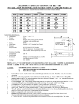
RATINGS OF “ACCUMIX MT” UNITS
*The heaters’ actual temperature rises are limited by their thermostatic controls.
The theoretical values shown above are only for comparison purposes.
1) Wire entry into the unit should be made through the upper left hand corner of
the backplate via one of the two “knockout” holes provided.
2) The “mains” wires should be connected to the lugs on the relay marked
L1 and L2 or N. The ground lead must be connected to the slot marked
Failure to ground the system may result in death or serious injury.
WARNING
BEFORE BEGINNING ANY WORK ON THE INSTALLATION
BE SURE THAT THE BREAKER IS “OFF”
TO AVOID ANY DANGER OF SHOCK.
FIGURE 2
OUTLET VALVE (B)
(ADJUST TO GIVE
APPROXIMATE
DESIRED TEMP.)
WIRE ENTRY
EITHER THROUGH
REAR OR TOP
KNOCK-OUTS
WARNING:
This water heater must not be switched on if there is
a possibility that the water in the heater is frozen.
MAXIMUM * TEMPERATURE RISE (F)
RATED OUTPUT AT AMPS
MODEL VOLTAGE RATED VOLTAGE DRAWN 0.5 gpm 1.0 gpm 1.5 gpm
MT004120T 120 3,500 W 29 48 24 16
MT005240T 240 4,800 W 20 66 33 22
MT007240T 240 6,500 W 27 89 44 30
MT010240T 240 9,500 W 40 130 65 43
MT004277T 277 4,100 W 15 56 28 19
MT008277T 277 8,000 W 29 109 55 36
MT010277T 277 10,000 W 36 137 68 46
4 1/4 inches
11 15/16
inches
MOUNTING HOLES
RELAY
ECO
Mechanical Thermostatic
Mixing Valve
(ASSE 1070-2004 Approved)
DO NOT ADJUST
Dimensions measured on
center with mounting holes
GROUND WIRE
INLET VALVE (A)
(FULLY OPEN)
5 4
/