Page is loading ...

Rev E 3/4/2016
INSTALLATION INSTRUCTIONS & HOME OWNERS MANUAL
TANKBUDDY™
IMPORTANT SAFETY INFORMATION
When installing or using any high voltage electrical appliance, basic safety precautions should always be
followed. Under no circumstance should you attempt to clean, install, inspect, repair, disassemble or
otherwise service this water heater, without first shutting off all power to the unit directly at the breaker
box. SERIOUS BODILY INJURY OR DEATH COULD OCCUR IF YOU IGNORE THIS WARNING.
WE RECOMMEND THAT THIS PRODUCT BE INSTALLED BY A QUALIFIED HOMEOWNER. IF FURTHER
ASSITANCE IS NEEDED, A LICENSED AND QUALIFIED PLUMBER AND ELECTRICIAN IN ACCORDANCE WITH
ALL APPLICABLE NATIONAL, STATE, PROVINCIAL, AND LOCAL PLUMBING AND ELECTRICAL CODES
SHOULD BE HIRED.
PLEASE READ THESE INSTRUCTIONS THOROUGHLY AND COMPLETELY PRIOR TO INSTALLATION & USE.
FAILURE TO DO SO COULD CAUSE PROPERTY DAMAGE, SERIOUS INJURY, OR DEATH.
This manual should be shown to all members of the household who plan to use this unit, and be retained for
future reference.
Tested and certified by the Water Quality Association against NSF/ANSI 372 for lead free
compliance.


1
ABOUT YOUR TANKBUDDY™
Congratulations on the purchase of your Eemax TankBuddy™!
The TankBuddy™ is a device that extends the usable hot water from your existing hot water storage device,
while maintaining the existing electrical power infrastructure.
TECHNICAL SPECIFICATIONS
Voltage
240 VAC
Max Amperage
30 Amps
Max Power Rating
7.2 kW
Pre-Set Outlet Temperature
120°F
Activation Temp Range
80-130°F
Outlet Temperature Range
80-140°F
Activation Flow Rate
0.3 GPM
To get the best performance and energy savings from your TankBuddy™, it is important that it be installed
in accordance with our instructions and the electrical and plumbing codes applicable to your area, and that
you read this manual thoroughly for important operating instructions and tips.
If you have questions at any time, please contact Eemax directly at:
Eemax Inc.
400 Captain Neville Drive, Waterbury, CT 06705
Toll Free: 1-800-543-6163, or 203-267-7890 Fax: 203-267-7975
CONTENTS
1. BEFORE INSTALLATION
2. SELECTING A LOCATION TO INSTALL
3. SETTING UP TO INSTALL
4. PLUMBING INSTALLATION
5. ELECTRICAL INSTALLATION
6. GENERAL OPERATING INSTRUCTIONS
7. MAINTENANCE
8. TROUBLE SHOOTING GUIDE
9. USER INTERFACE

2
1- BEFORE INSTALLATION
PLEASE READ THESE INSTRUCTIONS THOROUGHLY AND COMPLETELY PRIOR TO INSTALLATION & USE.
FAILURE TO FOLLOW INSTRUCTIONS COULD CAUSE PROPERTY DAMAGE, SERIOUS PERSONAL INJURY, OR
DEATH.
By installing this product, you acknowledge the terms of the manufacturer’s warranty. Once the heater is
installed, do not return product to the place of purchase. If you have any questions regarding the warranty or
product return policies, please contact us at 1-800-543-6163.
Inspect all components. The contents of your box should include the following components:
TankBuddy™ Unit
½“ Ferrule (2x)
½“ Nut (2x)
⅝” Tube to ¾“ NPT Female Adapter (1x)
Push-to Connect Fitting (With ½” Copper Pipe Sample) (2x)
Cable Clamp (2x)
Wire Nuts (1x)
Pigtail Cord (1x)
What you will need to install:
Phillips Head Screwdriver
Flat Head Screwdriver
Pipe Cutter
Adjustable Wrench
Teflon Tape
Tape Measure/Ruler
Pencil (recommended for marking measurements when cutting pipe)
Needle-Nose Pliers (not required but may be beneficial)
2- SELECTING A LOCATION TO INSTALL
This product is designed to be installed indoors only, in series with your pre-existing tank water heater.
DO NOT install this product in a location where it may be subject to freezing temperatures. If the water inside
your unit freezes, it can cause severe and permanent damage that is not covered under your warranty.
DO NOT locate the water heater in a location that is difficult to access.
SCALD RISK: Make sure that the water heater and hot water outlet pipe are out of the reach of children so they
cannot tamper with the temperature controls or injure themselves by touching the hot water outlet pipe. The
outlet water pipe can get very hot.
This product does NOT require venting.
Avoid installing your unit in a location prone to excessive humidity, moisture, or dust, or in an area where it may
be splashed with water or other liquids. DO NOT install under water pipes or air conditioning lines that might
leak or condense moisture that could then drip onto the heater. DO NOT install above electrical boxes or
junctions.
If you plan to install your water heater on a second floor or in a heated attic space, make sure that you follow all
code requirements for such installations as required for your area. You can install an active water leak detector
and shutoff valve designed to turn off your water supply in the event that a leak is ever detected.

3
3- SETTING UP TO INSTALL
Recommended Clearances:
At least 14 inches from above the existing tank heater to the next obstruction
6 inches in front of and to the sides of the TankBuddy™, for service maintenance
Pre-Mounting Steps
1. SHUT OFF ELECTRICITY ON YOUR CIRCUIT BREAKER BEFORE PROCEEDING TO ANY FURTHER
INSTALLATION STEPS.
2. Make sure there is at least 14 inches of straight pipe clearance above the tank heater. This is the
required room in order for the unit to effectively connect in series with the tank and outlet pipe.
IF SPACIAL ISSUES ARISE, OR IF THE COPPER PIPE IS NOT STRAIGHT (ABNORMAL PIPING THAT IS
NOT STRAIGHT), AN ADDITIONAL PLUMING HOSE MAY NEED TO BE USED.
3. Close the supply water valve to the tank heater, located in most cases above the tank heater on the
cold water inlet side. You must do this to drain your system.
4. Open the drain valve of the water tank to let the tank completely deplete of water. The drain valve
is usually located near the bottom of the tank.
5. Drain the water from all existing hot water pipes by first opening all hot water faucets of any kind in
the house. Leave the faucets open until plumbing installation is complete. If water does not stop
flowing, check to make sure the inlet water to the tank heater has been completely shut off.
6. Assess your plumbing system before you cut the pipe – possible plumbing layouts on the following
page
CUTTING THE PIPE IS A CRITICAL STEP. IT IS IMPERATIVE YOU REFER TO THE GUIDE ON THE
FOLLOWING PAGES FOR CLEAR INSTRUCTIONS ON HOW TO CUT THE HOT COPPER PIPE.
Note: If you do not have any of the following plumbing layouts, we recommend you then hire a
licensed and qualified plumber to perform this portion of the installation.

4
Possible Pre-Existing Plumbing Layouts
Hot Water
Copper Pipe
Hot Water Outlet
Connection Fitting
(Can be variety of fittings)
Hot Water
Copper Pipe
Hot Water Outlet
Connection Fitting
(Can be variety of fittings)
Hot Water
Copper Pipe
Hot Water Outlet
Connection Fitting
(Can be variety of fittings)
Irremovable or essential union
(Can be variety of fittings)
At least 1 ½”
of vertical pipe
movement
At least 1 ½”
of vertical pipe
movement
Layout A
At least 14 inches of straight pipe above tank
At least 1 ½” of vertical pipe movement (ability
to raise pipe)
Turn to page 5
Layout B
At least 20 inches of straight pipe above tank
At least 1 ½” of vertical pipe movement (ability to
raise pipe)
Irremovable or essential union used in plumbing
Turn to page 6
Layout C
At least 14 inches of
straight pipe above tank
No vertical movement of
pipe (Pipe is completely
restricted or braced)
Turn to page 7
No vertical movement
(Pipe is completely
restricted or braced)

5
Cutting the Copper Hot Water Pipe – Layout A
Please follow all pre-installation instructions carefully. We recommend that this product be installed by a
qualified homeowner. If further assistance is needed, a licensed and qualified plumber in accordance with
all applicable national, state, provincial, and local plumbing codes should be hired.
1. Locate the hot water outlet connection on your pre-existing water tank. On the copper pipe, mark
with a pencil 2 inches above the topmost point of the hot water outlet connection fitting.
2. Using a pipe cutter, cut the hot water copper pipe at this 2-inch mark (Cut A), being as accurate as
possible. Refer to Figure A. Once accomplished, unscrew the original connection fitting from the
outlet thread of the tank.
3. On the now exposed tank outlet thread, screw on the Female NPT Adapter (reference pg. 9), tightly
securing this connection. Wrap the thread 2-3 times with Teflon Tape to seal the connection and
prevent leaks.
4. Now from the in-place Female NPT adapter, measure upwards EXACTLY 11 ⅛ inches. Refer to
Figure B. Mark this on the copper pipe with a pencil. IT IS IMPERATIVE THAT ACCURACY BE USED
DURING THIS STEP. CUTTING THE PIPE TOO MUCH WILL PREVENT A SECURE CONNECTION FROM
TAKING PLACE.
5. Cut the pipe at the 11 ⅛ inch mark (Cut B), taking extreme care for accuracy. If the installer is less
experienced or unsure, it is advised to cut the pipe slightly below the 11 ⅛ inch mark. It is safer to
cut too little and correct a mistake than to cut too much.
6. Secure a Push-to-Connect fitting onto the hanging copper pipe, making sure there are no stray or
jagged pieces of copper stemming from the pipe. Make sure the Push-to-Connect fitting is pushed
as far up as possible onto the copper pipe, fully sealing the connection.
7. Proceed to Plumbing Installation on page 8 with reference guide on page 9.
Hot Water
Copper Pipe
Hot Water Outlet
Connection Fitting
(Can be variety of fittings)
2”
Figure A.
Cut A.
11 ⅛”
Figure B.
Cut B.
¾” Female NPT to
⅝” Tube Adapter

6
Cutting the Copper Hot Water Pipe – Layout B
Please follow all pre-installation instructions carefully. If further assistance is needed, a licensed and
qualified plumber in accordance with all applicable national, state, provincial, and local plumbing codes
should be hired.
1. Locate the irremovable or essential union on the hot water pipe. On the copper pipe, mark with a
pencil 2 inches above the topmost point of the irremovable/essential union. Refer to Figure C.
2. Using a pipe cutter, cut the hot water copper pipe at this 2-inch mark (Cut C), being as accurate as
possible. Refer to Figure C. Do not remove any pipe yet, simply perform cut C.
3. Now measure upwards EXACTLY 12 ½ inches from cut C. Refer to Figure D. Mark this on the copper
pipe with a pencil. IT IS IMPERATIVE THAT ACCURACY BE USED DURING THIS STEP. CUTTING THE
PIPE TOO MUCH WILL PREVENT A SECURE CONNECTION FROM TAKING PLACE.
4. Cut the pipe at the 12 ½ inch mark (Cut D), taking extreme care for accuracy. If the installer is less
experienced or unsure, it is advised to cut the pipe slightly below the 12 ½ inch mark. It is safer to
cut too little and correct a mistake than to cut too much.
5. Secure the Push-to-Connect fittings onto BOTH exposed ends of the copper pipe, making sure there
are no stray or jagged pieces of copper stemming from the pipes. Make sure the Push-to-Connect
fittings are pushed as far as possible onto the copper pipe, fully sealing the connection.
6. Proceed to Plumbing Installation on page 8, with reference guide on page 10.
Hot Water
Copper Pipe
Hot Water Outlet
Connection Fitting
(Can be variety of fittings)
Irremovable or essential union
(Can be variety of fittings)
Figure C.
2”
Cut C.
Irremovable or
essential union
Figure D.
2”
12 ½“
Cut D.
Cut C.

7
Cutting the Copper Hot Water Pipe – Layout C
Please follow all pre-installation instructions carefully. We recommend that this product be installed by a
qualified homeowner. If further assistance is needed, a licensed and qualified plumber in accordance with
all applicable national, state, provincial, and local plumbing codes should be hired.
This set-up addresses the issue of not having free space to vertically move the hot water pipe up in order to
make a secure connection. This typically occurs if there is very low ceiling height or the copper pipe is
braced or restricted.
In order to install your unit, you will need to purchase an intermediate hose.
We recommend using a ¾” Repair Hose Push Fitting. This type
of hose has Push-to-Connect fittings on either side, and can be
used efficiently for this application. Hoses such as the one
shown can be purchased at a low cost at most home center
stores.
An alternative recommendation is to purchase a water heater
installation kit. This could also help with the installation process such as
Layout C. A kit such as the one shown can be purchased at a low cost
at most home center stores.
This method of installation requires more experience and judgment from the homeowner, because each
household may have a moderately different layout in this situation.
For further installation assistance, please call or email our customer service and technical support team for
any help you may need.
Toll Free: 1-877-474-6473, or 305-623-7900
support@ecosmartUS.com

8
4- PLUMBING INSTALLATION
Please follow all plumbing instructions carefully. We recommend that this product be installed by a
qualified homeowner. If further assistance is needed, a licensed and qualified plumber in accordance with
all applicable national, state, provincial, and local plumbing codes should be hired.
Plumbing Installation Instructions
Please see installation diagrams on the following pages for visual guidance.
STEP 1: Using the corresponding fittings for which layout was used, connect the HOT WATER outlet from
your water tank to the INLET thread located on the bottom side of the TankBuddy™ when facing the unit.
Use the nut (B) and ferrule (C) to secure the connection. Do not over tighten the compression nuts, which
may cause the ferrules to crack and lead to a leak.
STEP 2: Using the PUSH-TO-CONNECT fitting (F), connect the HOT WATER copper pipe line to OUTLET
thread located on the top side of the unit. Use the nut (E) and ferrule (D) to secure the connection.
STEP 3:
Close the tank drain valve.
Make sure at least one warm water faucet is open in the house.
Re-open the water supply valve on the cold water copper pipe.
You know the tank is full when water is running out of any open faucet in the house.
FAILURE TO FOLLOW THESE STEPS WILL CAUSE WATER TANK DAMAGE.
STEP 4: After tightening all fittings, open several hot water faucets and allow un-heated water to run
though the water heater for at least 2 to 3 minutes. This process purges all the air from the water lines and
MUST be performed prior to turning on the power at the unit.
FAILURE TO FOLLOW THIS STEP CAN CAUSE PERMANENT DAMAGE TO THE HEATING ELEMENTS.
If any maintenance is performed on the water heater or the home’s plumbing system that may introduce
air into the plumbing pipes, it is important to turn the power off to the water heater and purge the air out
of the lines before allowing the unit to power up.
STEP 5: Carefully inspect all connections, unions, and the pressure relief valve (if installed) for leaks.
STEP 6: TURN OFF ALL FAUCETS BEFORE PROCEEDING TO ELECTRICAL INSTALLATION.

9
Plumbing Installation Visual Guidance – Layout A
A.
F.
Existing Household Plumbing
.875”/ ¾ Copper Tube
Push-to-Connect Fitting
½“ Nut
½” Ferrule
½“ Nut
½” Ferrule
¾” Female NPT to ⅝” Tube Adapter
Existing ¾” Male NPT From Tank
(OUTLET SIDE OF TANK)
D.
B.
E.
C.
Step 2
Step 1

10
Plumbing Installation Visual Guidance – Layout B
F.
Existing Household Plumbing
.875”/ ¾ Copper Tube
Push-to-Connect Fitting
Existing Household Plumbing
.875”/ ¾ Copper Tube
F.
Push-to-Connect Fitting
Step 2
Step 1
½“ Nut
½” Ferrule
E.
D.
½“ Nut
½” Ferrule
B.
C.

11
IMPORTANT NOTES:
1. This unit should not require soldering any pipes for installation. Heat from soldering may damage the
flow sensor in the unit.
2. This unit is equipped with both computer-controlled and electro-mechanical auto resetting thermostat
switches for high-limited temperature protection. Since this product does not use a storage tank, the
use of a temperature pressure relief valve (T&P) is not required for most installations. UL Standard 499
does NOT require that a pressure relief valve be used. However, a T&P valve may be required to meet
installation codes in your area. If one is required, install the pressure relief valve in accordance with
local codes and ensure that it operates correctly and that air is purged from the valve prior to installing
the water heater. When connecting to Flex or High Temperature CPVC pipe, we recommend that a T&P
valve be used for added safety.
Please note: Installations in the Commonwealth of Massachusetts and State of Kentucky require a
pressure relief valve. Please check your local installation codes for any special requirements.
3. The maximum operating water pressure is 150 PSI. If the water pressure is higher, a pressure reducing
valve must be installed on the main incoming water supply line prior to installing the unit.
4. When connecting the inlet water pipe to the unit, make sure to use a wrench to hold the unit’s
connection, and another wrench to tighten, so the flow sensor on the unit is not loosened or damaged.
Serious internal damage to the water heater can occur if the inlet or outlet connections are over
tightened or if solder connections were made.
5. We recommend that a manual shut-off valve (ball valve) be installed on the inlet and outlet of the water
heater so there is a convenient shut-off point available in the event that future maintenance or servicing
is required. Before connecting pipes to the water heater, it is extremely important to flush the lines to
eliminate all plumbing paste or residue in the lines caused by any brazing or soldering.
We recommend that all the water pipes or hoses within 3 feet of the inlet and outlet connections be rated for
high temperature applications with a 150°F minimum.

12
5- ELECTRICAL INSTALLATION
We recommend that this product be installed by a qualified homeowner. If further assistance is needed, a
licensed and qualified electrician in accordance with all applicable national, state, provincial, and local
electrical codes should be hired. As with all electrical appliances, under no circumstances should you
attempt to install, repair or disassemble this water heater without first shutting off all power to the unit
directly at the fuse or breaker box. Make sure to shut off all breakers. SERIOUS BODILY INJURY OR DEATH
CAN OCCUR IF YOU IGNORE THIS WARNING.
All wiring (wire gauge) and circuit protection (breakers) must comply with the U.S. National Electrical Code
(NEC) in the USA, or the Canadian Electrical Code (CEC) in Canada. Failure to do so could result in property
damage and/or personal injury, and void your warranty. Note: the Canadian Electrical Code generally
requires that all supply wires and corresponding circuit protection used for domestic hot water heating and
hydronic heating applications be sized to a minimum of 125% of the maximum current rating of the heater
(see model specifications below for details).
Before installing this product, ensure that the home has sufficient electrical power available to handle the
maximum amperage load of the applicable model. TURN OFF THE ELECTRICAL POWER BEFORE
PROCEEDING.
Electrical Installation Instructions
STEP 1: Making sure all electrical power is shut off, remove the black, red, and ground wires from the
existing tank heater coming from the circuit breaker. These wires will now go into the TankBuddy™
through the hole in the unit’s back plate (see wiring diagram and Connection Reference 1 on the
subsequent pages).
STEP 2: Using a suitable wire gauge that meets all applicable electrical codes for the size of the breakers
used, run Line 1 (black wire), Line 2 (red wire), and ground (green wire) from the home’s main breaker
panel to the TankBuddy™ water heater, through the back plate hole. This is connection reference 1,
specified on page 14.
Note: A separate ground conductor for each incoming circuit is required.
STEP 3: Connect the supplied pigtail cord to the TankBuddy™. See Connection Reference 2 on page 15.
STEP 4: Now connect the wires included with the TankBuddy™ (pigtail cord stemming from the unit) to the
existing tank heater. The black, red, and green (ground) wires should all have secure connections.
MAKE SURE THESE CONNECTIONS ARE IN AN ENCLOSED AREA. EXPOSED CONNECTIONS CAN LEAD TO
SERIOUS INJURY OR DEATH.
STEP 5: DOUBLE CHECK the electrical connections to make sure they are correct and that all wire
connections are tight and secure. Also confirm that the correct breaker size and wire gauge has been used
and confirm that the unit has been connected to a ground in accordance with applicable codes.
STEP 6: Confirm that all the air has been purged from the water lines prior to turning on power to the unit.
Refer to STEP 4 in the plumbing installation section.
CAUTION: Ensure that you have made the correct connections. You must follow the wiring connection as
shown to ensure the proper operation of the unit. If you mix up one set of wires with another, the unit will
not operate correctly even though it turns on and otherwise appears to function properly.

13
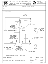
Electrical Wiring Diagram
Normal Tank Configuration:
TankBuddy™ and Electric Tank Configuration:
Connection Reference 1, shown on page 14.
Connection Reference 2, shown on page 15.

14
Connection Reference 1
Connecting Lines 1 & 2 from the circuit board (existing service) to the TankBuddy™:
1. Remove the control knob from the unit, then remove the cover of the unit. Two
screws (located on the side of the unit) must be removed in order to do this.
2. For this step, if the leads from the breaker are wrapped in a common household
cable jacket, make sure the ends of the leads are exposed from the external
jacket for at least 10 inches. Strip back 3/8” to bare copper on L1 & L2.
Lines 1 & 2 and ground (from the circuit breaker) will be connected to the
TankBuddy™’s inner terminal block. Make sure to thread these lines into the
heater from the backside via the back plate hole, using the supplied cord
grommet.
Connect Line 1 (black) to the “L1” labelled wire terminal, and Line 2 (red) to
the “L2” labelled wire terminal, using a flathead screwdriver to secure the
terminal.
Using a supplied wire nut, connect the circuit breaker ground wire to the green ground wire
stem already inside the unit, which will be exposed. Twist wires together, then twist the wire
nut with both wires inside to secure the connection.
L1/L2 Terminals
Back Plate Hole
(Installer must secure cable clamp here)
3. Tighten the connections on the terminal block with a flathead screwdriver. MAKE SURE WIRES ARE
INSERTED ALL THE WAY IN THE TERMINAL, AND THAT THE SCREWS SECURING THE CONNECTION
ARE TIGHT AND SECURE. FAILURE TO DO THIS WILL CAUSE HEATER MALFUNCTION. Also, make
sure that the wire insulation is not inserted into the terminal block as this will inhibit good electrical
connection.
4. Proceed to Connection Reference 2 on following page.
Cable Clamp
Wire Nut

15
Connection Reference 2
Connecting the pigtail cord to the TankBuddy™:
1. The pigtail cord should be partially attached to the unit through the ground connection. With the
cover off, you should see an exposed red wire and black wire coming from the pigtail, on the end
that’s inside the unit. Connect the red wire to the left-most terminal, and the black wire to the
right-adjacent terminal.
2. Tighten the connections on the terminal block with a flathead screwdriver. MAKE SURE WIRES ARE
INSERTED ALL THE WAY IN THE TERMINAL, AND THAT THE SCREWS SECURING THE CONNECTION
ARE TIGHT AND SECURE. FAILURE TO DO THIS WILL CAUSE HEATER MALFUNCTION. Also, make
sure that the wire insulation is not inserted into the terminal block as this will inhibit good electrical
connection.
3. Replace the unit cover, screws, and control knob.

16
6- GENERAL OPERATING INSTRUCTIONS
Operating your new unit is very similar to using any traditional water heating system. However, it is very
important that you carefully read all of the set-up procedures and operating instructions and tips to ensure
the maximum performance and energy savings from your new water heater. We recommend that all
members of the household read these General Operating Instructions.
How your new unit works: The TankBuddy™ combines with the traditional hot water tank to provide an
extremely effective and efficient way of heating your home. The unit reads the temperature coming out of
the tank, and will turn on if the water drops below a set temperature, which you can set. The booster will
keep the water at the desired temperature, another limit which you can set.
7- MAINTENANCE
To ensure maximum performance of your unit and to reduce the risk of a water leak, we recommend the
following maintenance:
You should inspect the connections on the inlet and outlet of the unit at least on an annual basis for any
signs of damage or failure. Any signs of damage, cracks, leakage or weakness should be addressed. Take
care not to over-tighten the connections. Serious internal damage to your water heater can occur if you
over-tighten the water heater connections at the unit.
IMPORTANT NOTES:
As with all electrical appliances, under no circumstances should you attempt to install, repair or
disassemble this water heater without first shutting off all power to the unit directly at the fuse or breaker
box. SERIOUS BODILY INJURY OR DEATH COULD OCCUR IF YOU IGNORE THIS WARNING.
When any maintenance is performed on the unit or the home’s plumbing system that may introduce air
into the plumbing pipes, it is important to turn the power off to the water heater and purge the air out of
the lines before allowing the unit to power up. FAILURE TO DO SO COULD CAUSE PERMANENT DAMAGE TO
THE HEATING ELEMENT AND VOID YOUR WARRANTY.
If you have a water supply with a high level of mineralization (hard water), you should increase the
frequency of your maintenance. Remove element and inspect for scale build up – soak in vinegar or de-
liming solution until scale is removed, typically within a few hours.
8- TROUBLE SHOOTING GUIDE
Are you having problems with your water heater?
Please call or email our customer service and technical support team for any help you may need.
TOLL FREE 1-800-543-6163

17
The following table represents some of the most common technical support questions we receive. Before calling
us, please read thoroughly to see if your question or problem is addressed.
PROBLEM
POSSIBLE CAUSE
SOLUTION
Unit is not heating at all (water is
flowing but the unit is not heating
at all — the outgoing water
temperature is the same as my cold
water supply) and/or the digital
display does NOT light up.
No power or incorrect
wiring.
Make sure the breakers at main electrical panel are ON. You may have a
faulty breaker or unit may be wired incorrect. Refer to page 13 for proper
wiring layout.
Internal part failure.
Please call us for technical assistance.
Unit is not heating at all (water is
flowing but the unit is not heating
at all - the outgoing water
temperature is the same as my cold
water supply) The digital display
DOES light up.
Internal part failure.
Please call us for technical assistance.
Flow rate is too low /
water pressure is too
low*
Your water heater has an activation flow rate of approximately 0.3 GPM. If
your water flow rate is less than this level, your unit will not activate.
Increase the flow rate.
Activation temperature
too low
The water heater will turn on when the temperature of the water at the
inlet of the TankBuddy™ falls below the activation temperature (when the
tank is not providing hot water). Increase activation temperature.
Unit is heating but the water
temperature is not hot enough.
User temperature setting
too low.
Turn up the temperature setting on the unit.
Voltage less than 240
volts.
The heating elements on your unit are designed for 240 volts. When use
with a lower voltage, they produce less heating power.
Mixing too much cold
water
You may have an anti-scald feature on your faucet that is mixing cold
water. These types of faucets can usually be adjusted to reduce the
amount of cold water mixed. Also, your tank may be completely out of
hot water and is mixing cold water. Give the tank time to recover or
reduce the amount of water you are using.
The water temperature at my
faucet is less than the temperature
setting of my water heater.
Voltage less than 240
volts.
The computer chips in your unit are programmed with the expectation
that your incoming line voltage is 240 volts. If you have less than 240
volts, it may affect the reading on your unit’s digital display and cause it to
read slightly higher than the actual output temperature. To compensate
for this, increase the setting on your unit if you need / want hotter water.
Anti-Scald
pressure/balancing valve
or tempering valve.
Your faucet may have an anti-scald feature or a tempering valve that
automatically mixes cold water even when you turn your control lever or
handle to full hot. These devices are usually adjustable so you can turn off
the cold mix completely. You can compensate for this by increasing the
setting on your unit if you need/want hotter water.
Thermal loss due to long
pipe run
As the hot water from the unit runs through the hot water delivery
system to your faucet, some heat will be lost especially if it has long
distance to travel or the pipes are cold. This is normal. You can
compensate for this by increasing the setting on your unit if you
need/want hotter water.
Pre-existing water tank is not
heating.
Incorrect wiring.
The unit may be wired incorrectly. Refer to page 13 for proper wiring
layout.
Relay switch is defective.
Please call us for technical assistance.
Unit displays 999 as inlet and/or
outlet temperature
Thermistor on
corresponding channel is
defective
The unit may be wired incorrectly. Refer to page 13 for proper wiring
layout.

18
9- USER INTERFACE
TankBuddy™ Features
List of Menu Options Provided by the Software (Clarified Below and on Following Page):
Inlet/Outlet Temperature Reading
Active Unit in Operation
Activation Temperature
Max Temperature
Software Version
Primary Menu Cycle Screens
Turn the control knob in either direction to cycle through menu options.
Inlet/Outlet Temperature Reading
The temperature of the water going in and out of the TankBuddy™ can be
observed from this display.
Active Unit in Operation
This screen will tell the user which heating unit is operating at that given
point in time. It will either be the pre-existing water tank (“TANK”) or the
TankBuddy™ (“UNIT”).
Flow
The flow screen will tell the user the amount of water that is flowing
through the unit in gallons per minute.
Load Factor
Here you can see how hard your TankBuddy™ is working.
Clock
Set the time here (HOURS:MINUTES:SECONDS). Press the knob to cycle
through hours, minutes, seconds and turn the knob to adjust the number.
IN 71 F
OUT 69 F
TANK OFF
UNIT ON
FLOW
0.00 GPM
PWM
88%
CLOCK
01:23:57
/