PLUMBING CONNECTIONS
1) The unit is supplied with compression fittings. USE THESE: DO NOT
USE THREADED PIPE FITTINGS. DO NOT USE PIPE DOPE
OR TEFLON TAPE ON THIS INSTALLATION. Ensure the inlet filter supplied
with this unit is in place.
2) Ensure that the pipes are correctly aligned with the inlet and
outlet bosses in order to avoid excessive stress on the heater body molding.
NOTE: Run water through the supply pipe to remove all debris from the
pipe before connecting to the unit. Failure to do so could damage the flow
switch.
3) Install isolating valves (full flow ball valve type) on both inlet and outlet
pipes. This allows the unit to be isolated for maintenance purposes. (Fig. 2)
4) When all plumbing is complete, inspect the system for water leaks
at all plumbing connections. If a water leak is present take corrective action.
If a water leak is at the compression fitting, slowly tighten compression nut
until the water leak ceases.
Fully open both inlet and outlet ball valves.
Run all hot water outlets fed by this heater one at a time for a minute or two
until the water flow is continuous, and free from “gulping” and from all visible
air
pockets.
NOTE:
ALL PLUMBING AND MOUNTINGMUST BE COMPLETED
BEFORE PROCEEDING WITH THE ELECTRICAL HOOK-
TEST THE INSTALLATION FOR LEAKS BEFORE
CONNECTING THE ELECTRICAL SUPPLY.
OPERATING THE WATER HEATER
IMPORTANT
Before switching “on” the power at the circuit breaker the hot
water circuit must be free of air pockets or premature failure of the heating element will
occur. To do this, open all hot water faucets one at a time for a minute or two until the
water flow is continuous and free from “gulping” and from visible air pockets.
1) With inlet and outlet BALL VALVES fully open, turn on all hot water outlets serviced
by the unit.
2) Run for 5 minutes, turning faucet “on” and “off” repeatedly.
3) Switch on electric supply at circuit breaker.
4) The power indicator light should now illuminate.
NOTE: At this point water temperature may not be very hot.
5) Using the OUTLET BALL VALVE slowly reduce water flow until desired
temperature is achieved at hot water outlet.
NOTE: The water temperature is proportional to the flow through the heater.
The lower the flow the higher the temperature and vice versa.
6) Check performance of flow switch by opening and closing outlet valve a few times.
The power indicator light should illuminate ONLY when water is flowing through the unit.
For expected temperature rise at various rates of flow see table 1.
NOTE: An EFC-9500-s-10 (9.5 kW) unit at 240 V will deliver 1 gallon per minute at
65
o
F temperature rise. For example, with incoming water temperature at 45
o
F the
unit will produce 1 gallon per minute at 110
o
F.
7) It is possible that drawing off cold water at comparatively high rates of flow
elsewhere in the building at the same time that the heater is working, could
cause premature element failure. Care should be taken not to starve the unit
of cold water. To prevent this from happening, open fully the main valve on
the cold supply to the building and throttle back the control valves to the other
cold water outlets.
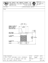
Hot water outlet
compression
fitting
DO NOT
SOLDER
Cold water inlet
compression
fitting
DO NOT
SOLDER
Fig 1
1 1/2 “
Inlet filter
Note: “Twin” comes with two faucet mounted aerators, these should
be mounted on both the faucets served by this unit. “Single” comes
with one faucet mounted aerator and 3/8” compression fittings with integral
flow restrictor.