Page is loading ...

Ceiling Fan Installation Manual
P2548
93081647_C

Date Pu rchased
Store Purchased
Model No.
Serial No.
Vendor No.
UPC
109226
785247214808
785247214815
785247214792
Limited Lifetime Warranty
Progress Lighting fan motors are warranted to the original purchaser to be free of electrical and/or mechanical defects for so
long as the original purchaser owns the fan. Pull chain switches, reverse switches, capacitors and metal finishes are warranted to
be free from defects in materials or workmanship for a period of 1 year from the date of purchase. Warping of wooden or plastic
blades is not covered by this warranty nor is corrosion and/or deterioration of any finishes for fans installed within ten miles of
any sea coast. Extended warranties for ENERGY STAR
®
qualified products may apply.
Progress Lighting ceiling fans with built-in LED light sources, when properly installed and under normal conditions of use, are
warranted to be free from defects in material and workmanship which cause the light sources to fail to operate in accordance
with the specifications for (i) five (5) years from the date of purchase on the LED Light modules and electrical components for
fans used in single family residences, and (ii) three (3) years from the date of purchase on the LED Light modules and electrical
components for fans used in multi-family or commercial applications. LED bulbs supplied by Progress Lighting carry no
warranty other than manufacturer’s warranty. Non-LED bulbs carry no warranty.
With proof of purchase, the original purchaser may return the defective fan to the place of purchase during the first 30 days for
replacement. After 30 days, the original purchaser MUST contact Progress Lighting at (864) 678-1000 for repair or replacement
which shall be determined in Progress Lighting’s sole discretion and shall be purchaser’s sole and exclusive remedy.
Labor and Shipping Excluded. This warranty does not cover any costs or fees associated with the labor (including, but not
limited to, electrician’s fees) required to install, remove, or replace a fan or any fan parts.
This warranty shall not apply to any loss or damage resulting from (i) normal wear and tear or alteration, misuse, abuse or
neglect, or (ii) improper installation, operation, repair or maintenance by original purchaser or a third party, including without
limitation improper voltage supply or power surge, use of improper parts or accessories, unauthorized repair (made or
attempted) or failure to provide maintenance to the fan.
THE FOREGOING WARRANTIES STATE PROGRESS LIGHTING’S ENTIRE WARRANTY OBLIGATION AND
ORIGINAL PURCHASER’S SOLE AND EXCLUSIVE REMEDY RELATED TO SUCH PRODUCTS. PROGRESS
LIGHTING IS NOT RESPONSIBLE FOR DAMAGES (INCLUDING INDIRECT, SPECIAL, INCIDENTIAL OR
CONSEQUENTIAL), DUE TO PRODUCT FAILURE, WHETHER ARISING OUT OF BREACH OF WARRANTY,
BREACH OF CONTRACT, OR OTHERWISE. THIS WARRANTY IS GIVEN IN LIEU OF ALL OTHER WARRANTIES,
WHETHER EXPRESSED OR IMPLIED, INCLUDING THOSE OF MERCHANTABILITY, FITNESS FOR A PARTICULAR
PURPOSE OR NONINFRINGEMENT.
Some states do not allow limitations on how long an implied warranty lasts or the exclusion or limitations of incidental or
consequential damages, so the above limitations and exclusions may not apply to you. This warranty gives you specific rights
and you may have other rights which vary from state to state.

Table of Contents
Safety Rules.....................................................................................................................................................................................
Unpacking Your Fan .......................................................................................................................................................................
Installing Your Fan .........................................................................................................................................................................
Installing the Light Kit....................................................................................................................................................................
Operating Your Transmitter ............................................................................................................................................................
Care of Your Fan ...........................................................................................................................................................................
Troubleshooting ............................................................................................................................................................................
Specifications ................................................................................................................................................................................
1.
2.
3.
8.
9.
10.
11.
12.

1. Safety Rules
1. To reduce the risk of electric shock, insure electricity has been turned off
at the circuit breaker or fuse box before beginning.
2. All wiring must be in accordance with the National Electrical Code and
local electrical codes. Electrical installation should be performed by a
qualified licensed electrician.
3. WARNING: To reduce the risk of electrical shock and fire, do not use
this fan with any solid-state fan speed control device.
4. WARNING: To reduce the risk of fire, electric shock, or personal injury,
mount to outlet box marked "Acceptable for Fan Support of 15.9 kg (35 lbs.)
Or Less" and use mounting screws provided with the outlet box. Most outlet
boxes commonly used for the support of light fixtures are not acceptable for
fan support and may need to be replaced. Due to the complexity of the
installation of this fan, a qualified licensed electrician is strongly
recommended.
WARNING
TO REDUCE THE RISK OF FIRE, ELECTRIC SHOCK OR PERSONAL
INJURY, MOUNT FAN TO OUTLET BOX MARKED ACCEPTABLE FOR
FAN SUPPORT.
5. The outlet box and support structure must be securely mounted and
capable of reliably supporting a minimum of 35 lbs (15.9 kg) or less.
Use only UL-listed outlet boxes marked FOR FAN SUPPORT.
6. The fan must be mounted with a minimum of 7 ft (2.1m) clearance from
the trailing edge of the blades to the floor.
7. To operate the reverse function on this fan, press the reversing button while
the fan is running.
8. Avoid placing objects in the path of the blades.
9. To avoid personal injury or damage to the fan and other items, be
cautious when working around or cleaning the fan.
10. Do not use water or detergents when cleaning the fan or fan blades. A
dry dust cloth or lightly dampened cloth will be suitable for most
cleaning.
11. After making electrical connections, spliced conductors should be
turned upward and pushed carefully up into the outlet box. The wires
should be spread apart with the grounded conductor and the
equipment-grounding conductor on one side of the outlet box.
12. Electrical diagrams are for reference only. Light kits that are not packed
with the fan must be UL Listed and marked suitable for use with the
model fan you are installing. Switches must be UL General Use
Switches. Refer to the Instructions packaged with the light kits
NOTE
READ AND SAVE ALL INSTRUCTIONS!
WARNING
TO REDUCE THE RISK OF PERSONAL INJURY, DO NOT BEND THE
BLADE ARMS (ALSO REFERRED TO AS BRACKETS) DURING
ASSEMBLY OR AFTER INSTALLATION. DO NOT INSERT OBJECTS IN
THE PATH OF THE BLADES.
WARNING
THIS PRODUCT CONTAINS CHEMICALS KNOWN TO THE STATE OF
CALIFORNIA TO CAUSE CANCER, BIRTH DEFECTS AND /OR OTHER
REPRODUCTIVE HARM. THOROUGHLY WASH HANDS AFTER
INSTALLING, HANDLING, CLEANING, OR OTHERWISE TOUCHING
THIS PRODUCT.

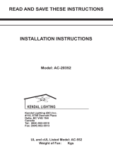
Unpack your fan and check the contents. You should have the following items:
Unpacking Your Fan 2.
12. Loose parts bag containing:
a. Blade attachment hardware
(16 screws, 16 fiber washers )
b. Mounting hardware
Wire nuts (3)
1. Fan blades (5)
2. Canopy assembly
3. Ball/downrod assembly
4. Coupling cover
5. Fan motor assembly
6. Mounting plate
7. LED light kit
8. Glass shade
9. Transmitter+holder+2 mounting screws
10. 9 volt battery
11. Balancing kit
3
1
2
10
4
9
11
5
6
7
8
12
a
b
9
V
o
l
t
B
a
t
t
e
r
y
LOW
OFF
HI
MED
REV

Tools Required
Phillips screw driver, straight slot screw driver,
adjustable wrench, step ladder, and wire cutters.
Mounting Options
If there isn't an existing UL listed mounting box,
then read the following instructions. Disconnect
the power by removing fuses or turning off
circuit breakers.
Secure the outlet box directly to the building
structure. Use appropriate fasteners and building
materials. The outlet box and its support must be
able to fully support the moving weight of the
fan (at least 35 lbs). Do not use plastic outlet
boxes.
Figure 4
Figure 3
Figure 1
Figure 2
Outlet box
Outlet box
Outlet box
Note: You may need a longer downrod to
maintain proper blade clearance when installing
on a steep, sloped ceiling.
To hang your fan where there is an existing
fixture but no ceiling joist, you may need an
installation hanger bar as shown in Figure 4
(available at your Progress Lighting Retailer).
3. Installing Your Fan
WARNING
TO REDUCE THE RISK OF FIRE, ELECTRIC
SHOCK, OR OTHER PERSONAL INJURY,
MOUNT FAN ONLY TO AN OUTLET BOX
MARKED ACCEPTABLE FOR FAN SUPPORT
AND USE THE MOUNTING SCREWS
PROVIDED WITH THE OUTLET BOX. OUTLET
BOXES COMMONLY USED FOR THE
SUPPORT OF LIGHTING FIXTURES MAY NOT
BE ACCEPTABLE FOR FAN SUPPORT AND
MAY NEED TO BE REPLACED. CONSULT A
QUALIFIED ELECTRICIAN IF IN DOUBT.
Angled ceiling
maximum
45 angle
Recessed
outlet box
Provide strong support
Ceiling
mounting
plate

Hanging the Fan
REMEMBER to turn off the power. Follow
the steps below to hang your fan properly:
Step 1. Remove the decorative canopy bottom
cover from the canopy by turning the cover
counter clockwise.(Fig. 5)
Step 2. Remove the mounting bracket from
the canopy by removing the 1 of 2 screws
from the bottom of the mounting bracket and
loosening the other one a half turn from the
screw head. Next, turn the canopy counter
clockwise to removing the mounting bracket
from the canopy. (Fig. 5)
Step 3. Pass the 120-volt supply wires
through the center hole in the ceiling hanger
bracket as shown in Fig. 6.
Step 4. Secure the hanger bracket to the
ceiling outlet box with the screws and
washers provided with your outlet box.
Step 5. Remove the hanger pin, lock pin and
set screws from the top of the motor
assembly.
Step 6. Route wires exiting from the top of
the fan motor through the collar cover,
canopy cover, canopy and then through the
ball / downrod. (Fig. 7)
Step 7. Align the holes at the bottom of the downrod
with the holes in the collar on top of the motor
housing (Fig. 7). Carefully insert the hanger pin
through the holes in the collar and downrod. Be
careful not to jam the pin against the wiring inside the
downrod. Insert the locking pin through the hole near
the end of the hanger pin until it snaps into its locked
position, as noted in the circle inset of Fig. 7.
Step 8. Tighten two set screws on top of the fan
motor firmly. (Figure 7)
Step 9. Place the downrod ball into the hanger
bracket socket.
WARNING
FAILURE TO PROPERLY INSTALL
LOCKING PIN AS NOTED IN STEP 7
COULD RESULT IN FAN LOOSENING AND
POSSIBLY FALLING.
Ceiling
hanger
bracket
Ceiling
canopy
Canopy
cover
CUL Listed
electrical
box
Ceiling
mounting
plate
Hook
Washers
120V Wires
Mounting
screws
(supplied with
electrical box)
Ball/downrod
assembly
Ceiling
canopy
Motor wires
Pin in locked
position
Tighten
screws
firmly
Locking pin
Canopy cover
Motor collar
Hanger pin
Collar cover
Figure 5
Figure 6
Figure 7
4.

5.
Make the Electric
Connections
WARNING: To avoid possible electrical shock,
be sure electricity is turned off at the main fuse box
before wiring.
Step 1. Motor to House Supply Wires Electrical
Connections: Connect the WHITE wire (Neutral)
from the outlet box to the WHITE wire marked
"AC in N" from the motor. (Fig. 8)
Step 2. Connect the BLACK wire (Hot) from the
outlet box to the BLACK wire marked "AC in L"
from the motor. (Fig. 8)
Secure all wire connections with the plastic wire
nuts provided.
Figure 8
Outlet Box
Black ("AC IN L")
White ("AC IN N")
White (Neutral)
Black (Hot)
Green or bare
copper (ground)
Ground (green)
(Connect to ground
wire on hanger
bracket if no house
ground wire exists.)

Finishing the Installation
Step 1. Tuck connections neatly into ceiling outlet
box.
Step 2. Slide the canopy up to mounting bracket
and place the key hole on the canopy over the screw
on the mounting bracket, turn canopy until it locks
in place at the narrow section of the key holes. (Fig.
9)
Step 3. Align the circular hole on canopy with the
remaining hole on the mounting bracket, secure by
tightening the two set screws. Note: Adjust the
canopy screws as necessary until the canopy and
canopy cover are snug.
WARNING
Make sure the notch on the hanging bracket properly
sits in the groove in the hanger ball before attaching
the canopy to the bracket by turning the housing until
it drops into place.
6.
Outlet box
Canopy cover
Canopy
Hanger
bracket
Figure 9
Screws
Figure 10
Fiber
washer
Screws
Blade
Slot
Attaching the Fan
Blades
Insert the blade through the slot in housing.
Align holes in blade and motor and secure with
3 screws and fiber washers. Repeat process
with the other blades. (Fig. 10)

Figure 12
Mounting
plate
Mounting ring
Screws
Installing the Mounting
Plate
Step 1.
Remove 1 of the 3 screws from the
mounting ring and loosen the other 2 screws.
(Do not remove)
Step 2.
Place the key holes on the mounting
plate over the 2 screws previously loosened from
the mounting ring, turn mounting plate until it
locks in place at the narrow section of the key
holes. Secure by tightening the 2 screws
previously loosened and the one previously
removed. (Fig. 12)
Blade balancing
All blades are grouped by weight. Because
natural woods very in density, the fan may
wobble even though the blades are weighed
equally.
The following procedure should correct most
fan wobbling problems. Check after each step.
1. Check that all blade and blade arm screws are
secure.
2. Most fan wobbling problems are caused
when blade levels are unequal. Check this
level by selecting a point on the ceiling
above the tip of one of the blades. Measure
this distance as shown in Figure 11. Rotate
the fan until the next blade is positioned for
measurement. Repeat for each blade. The
distance deviation should be equal within
1/8".
3. Use the enclosed Blade Balancing Kit if the
blade wobble is still noticeable.
4. If the blade wobble is still noticeable,
interchanging two adjacent (side by side)
blades can redistribute the weight and
possibly result in smoother operation.
Touching
ceiling
Figure 11
WARNING
TO REDUCE THE RISK OF PERSONAL
INJURY, DO NOT BEND THE BLADE
HOLDERS WHILE INSTALLING,
BALANCING THE BLADES, OR CLEANING
THE FAN. DO NOT INSERT FOREIGN
OBJECTS BETWEEN ROTATING FAN
BLADES.
7.

Installing the Light Kit
8.
CAUTION: Before starting installation,
disconnect the power by turning off the circuit
breaker or removing the fuse at fuse box. Turning
power off using the fan switch is not sufficient to
prevent electric shock.
Step 1. Remove the 1 of 3 screws from the posts
of the mounting plate and keep it for future use.
Loosen the other 2 screws. (Do not remove) (Fig.
13)
Step 2. While holding the LED light kit under
your fan, make the polarized plug connections:
- Blue to white
- Black to black
Step 3. Place the key holes in the LED light kit
over the two screws previously loosened from the
mounting plate. Turn the LED light kit until the
LED light kit locks in place at the narrow section
of the key holes. (Fig. 13)
Step 4. Securely tighten the two light kit
mounting
screws previously loosened and the one
previously removed. (Fig. 13)
Step 5. Raise glass shade up against the LED
light kit, and secure it to fan by turning glass
clockwise until snug. DO NOT OVERTIGHTEN.
(Fig. 13)
Figure 13
Screws
Mounting plate
Wire connector
LED light Kit
Glass
shade
Installing the battery
Install 9 volt battery (included), to prevent damage
to transmitter, remove the battery if not used for
long periods.
Figure 14
9 Volt
Battery

9. Operating Your Transmitter
Automated Learning Process
CAUTION: The remote control transmitter can
be programmed to multiple receivers or fans. If
this is not desired, turn wall switch off to any
other programmable receiver or fan.
This remote control transmitter is equipped with
16 code combinations to prevent possible
interference from or to other remote units such
as garage door openers, car alarms or security
systems. If you find that your fan and light go on
and off without using your remote control,
simply change the combination code in your
remote control transmitter.
To set the code,
perform these steps:
1. Remove battery cover from back side of
transmitter.
2. Use a ballpoint pen or a small screwdriver to
set the code switches 1 through 4 for the
transmitter.
Note: Since this fan comes with an
LED module, the dimmer switch (labeled D and
X) has been pre-set to the "ON" position (D). If
you do not wish to have dimming capability,
please move the switch to the "OFF" position
(X). (Fig. 15)
3. Restore electrical power and then set slider switch
on wall control to the ON position. Within 30
seconds of turning on the wall control, press and
hold the "OFF" button on the front of the transmitter
for 5 seconds or until light on fan blinks twice.
(Fig.
15)
4. Test the fan and light functions to confirm the
learning process is complete.
Figure 15
1
Code
Figure 16
1.
HI
,
MED
, and
LOW
buttons:
These three buttons are used to set the fan speed as
follows:
HI
= high speed
Med
= medium speed
Low
= low speed
2.
OFF
button:
This button turns the fan off.
3. button:
This button controls the light. Press and release the
button to turn the light ON or OFF. Press and hold the
button to set the desired brightness. The light key has
an auto-resume, it will stay at the same brightness as
the last time it was turned off.
LOW
OFF
HI
MED
REV

Care of Your Fan 10.
Here are some suggestions to help you maintain your
fan
1. Because of the fan's natural movement, some
connections may become loose.
Check the support
connections, brackets, and blade attachments
twice a year.
Make sure they are secure.
(It is not
necessary to remove fan from ceiling.)
2. Clean your fan periodically to help maintain its new
appearance over the years. Use only a soft brush or
lint-free cloth to avoid scratching the finish. The
plating is sealed with a lacquer to minimize
discoloration or tarnishing. Do not use water when
cleaning. This could damage the motor, or the wood,
or possibly cause an electrical shock.
3. You can apply a light coat of furniture polish to the
wood blades for additional protection and enhanced
beauty. Cover small scratches with a light application
of shoe polish.
4.
There is no need to oil your fan.
The motor has
permanently lubricated bearings.
IMPORTANT
MAKE SURE THE POWER IS OFF AT THE
ELECTRICAL PANEL BOX BEFORE YOU
ATTEMPT ANY REPAIRS. REFER TO THE
SECTION "MAKING ELECTRICAL
CONNECTIONS"
Figure 17
Figure 18
4. The "
REV
" button is used to set the fan
forward or reverse, press the button forward (for
warm weather) or reverse (for cool weather).
Speed settings for warm or cool weather depend on
factors such as the room size. Ceiling height, number of
fans and so on.
NOTE: To operate the reverse function on this fan,
press the reverse button while the fan is running.
Warm weather - (Forward) A downward air flow
creates a cooling effect as shown in Figure 17. This
allows you to set your air conditioner on a higher
setting without affecting your comfort.
Cool weather - (Reverse) An upward airflow moves
warm air off the ceiling area as shown in Figure 18.
This allows you to set your heating unit on a lower
setting without affecting your comfort.

11. Troubleshooting
Solution
1. Check circuit fuses or breakers.
2. Check line wire connections to the fan and switch wire connections in the switch housing.
CAUTION: Make sure main power is off.
3. Check to make sure the dip switches from the transmitter and receiver are set to the same frequency.
1. Make sure all motor housing screws are snug.
2. Make sure the screws that attach the fan blade bracket to the motor hub is tight.
3. Make sure wire nut connections are not rubbing against each other or the interior wall of the switch housing.
CAUTION: Make sure main power is off.
4. Allow a 24-hour "breaking-in" period. Most noise associated with a new fan disappear during this time.
5. If using an optional light kit, make sure the screws securing the glassware are tight. Check that light bulb is also secure.
6. Some fan motors are sensitive to signals from solid-state variable speed controls. If you have installed this type of control,
choose and install another type of control.
7. Make sure the upper canopy is a short distance from the ceiling. It should not touch the ceiling.
1. Check battery power in the remote control.
2. Do not connect the fan with wall mounted variable speed control (s).
3. Check to be sure code switches are set properly in remote control transmitter and wall control, and the learning process are
complete.
Problem
Fan will not start.
Fan sounds noisy.
Remote control
malfunction

Specifications 12.
28.16
lbs
31.35
lbs
2.62'
Fan Size Speed
Volts
Amps
Watts
RPM
CFM
N.W. G.W. C.F.
60"
Low
High
120
120
These are approximate measures. They do not include Amps and Wattage used by the light kit.
0.28
0.66
15
79
44
114
2116
5717
2017 Progress Lighting, Inc.
701 Millennium Blvd.,
Greenville, SC 29607
All Rights Reserved
c

Manual de Instalación del Ventilador de Techo
P2548
93081647_C

Fecha de compra
Lugar de compra
N de modelo.
N de serie
Numero de vendedor
UPC
109226
785247214808
785247214815
785247214792
Garantía limitada de por vida
Se garantiza al comprador original que los motores de los ventiladores de Progress Lighting no
presentan defectos mecánicos o eléctricos por el tiempo durante el cual el comprador original sea
dueño del ventilador. Los interruptores de cadena, interruptores de reversa, capacitadores y
acabados de metal tienen garantía por 1 año. La deformación de las aspas de plástico o madera no
está cubierta por esta garantía.
Con comprobante de compra, el comprador podrá devolver el ventilador defectuoso al lugar de
compra, durante los primeros 30 días, para su reemplazo. Pasados los 30 días, el comprador DEBE
contactarse con Progress Lighting para la reparación o el reemplazo, que se determinará a criterio
exclusivo de Progress Lighting y será la compensación única y exclusiva del comprador.
Se excluye la mano de obra y el envío. Esta garantía no cubre los costos o cargos asociados con la
mano de obra (incluidos, entre otros, los honorarios del electricista) necesaria para instalar, quitar o
reemplazar el ventilador o cualquiera de sus partes.
LA COMPENSACIÓN ÚNICA Y EXCLUSIVA DEL COMPRADOR ORIGINAL POR UN
RECLAMO DE CUALQUIER TIPO CON RESPECTO A ESTE PRODUCTO SERÁ LA QUE SE
INDICA EN EL PRESENTE. PROGRESS LIGHTING NO ASUME RESPONSABILIDAD POR
DAÑOS (INCLUIDOS INDIRECTOS, ESPECIALES, INCIDENTALES O EMERGENTES),
DEBIDO A FALLAS DEL PRODUCTO, YA SEA QUE SURJAN DEL INCUMPLIMIENTO DE
LA GARANTÍA, DEL INCUMPLIMIENTO CONTRACTUAL O DE OTRO MODO. LA
PRESENTE GARANTÍA SE OTORGA EN LUGAR DE TODAS LAS OTRAS GARANTÍAS,
EXPRESAS O IMPLÍCITAS, INCLUIDAS LAS DE COMERCIABILIDAD E IDONEIDAD
PARA UN FIN PARTICULAR, O CONTRA INFRACCIÓN, Y QUEDA NULA EN CASO DE
ABUSO, USO INDEBIDO O MANEJO INCORRECTO, NEGLIGENCIA, DAÑO DURANTE EL
ENVÍO, REPARACIONES NO AUTORIZADAS (REALIZADAS O QUE SE INTENTÓ
REALIZAR) O APLICACIÓN INUSUAL.
Algunos estados no permiten limitaciones sobre la duración de una garantía implícita o la exclusión
de limitaciones de daños incidentales o emergentes, de modo que las limitaciones y exclusiones
anteriores tal vez no se apliquen a su caso. La presente garantía le otorga derechos específicos y es
posible que usted tenga otros derechos que varían según el estado.

Tabla de Contenido
Normas de seguridad .......................................................................................................................................................................
Cómo desembalar el ventilador ......................................................................................................................................................
Cómo instalar el ventilador .............................................................................................................................................................
Instalación del kit de luz .................................................................................................................................................................
Operando su transmisor ..................................................................................................................................................................
Cómo cuidar del ventilador ...........................................................................................................................................................
Resolución de problemas ..............................................................................................................................................................
Especificaciones ............................................................................................................................................................................
1.
2.
3.
8.
9.
10.
11.
12.

1. Normas de seguridad
1. Para reducir el riesgo de eléctrocución, asegurarse de que la eléctricidad se
ha desactivado en el cortacircuitos o caja de fusibles antes de comenzar.
2. Todo cableado debe relizarse conforme al Código Electrico Nacional y los
códigos electricos locales. La instalación eléctrica debe ser relazada por un
eléctricista registrado calificado.
3. ADVERTENCIA: Para reducir el riesgo de una electrocuion e incendio,
no usar este ventilador con ningun dispositivo de esto s lido para control
de la velocidad del ventilador.
4. ADVERTENCIA: para reducir el riesgo de incendio, descarga eléctrica o
lesión personal, monte a una caja distribución marcada como "Aceptable para
soporte de un ventilador de 15.9kg (35 lbs.) de peso o menos" y monte con
los tornillos proporcionados con la caja de distribución. La mayoría de las
cajas de conexión utilizadas para soportar artefactos de iluminación, no son
aptas para colgar un ventilador y podría ser necesario cambiarlas. Debido a la
complejidad de la instalación de este ventilador, se recomienda
encarecidamente que la realice un electricista licenciado cualificado.
ADVERTENCIA
PARA REDUCIR EL RIESGO DE INCENDIO ELECTROCUCIÓN O
LESIONES PERSONALES. MONTAR EL VENTILADOR EN UNA CAJA DE
DISTRIBUCIÓN MARCADA CÓMO ACEPTABLE PARA SOPORTE DE
VENTILADORES.
5. La caja de distribución y la estructura de soporte deben estar montados
de manera segura y deben ser capaces de soportar, de manera confiable,
unminimo de 35 libras (15,9 kilogramos). Usar solamente cajas de
distribución listadas por UL. marcadas "PARA SOPORTEDE
VENTILADORES".
6. EL ventilador debe estar montado con un m nimo de 7 pies (2.1m) de
espacio libre desde el borde posterior de las aspas hasta el piso.
7.
Invierta el ventilador con el motor encendido a cualquier velocidad.
8. Evitar colocar objetos qen interfiera el giro de las aspas.
9. Para evitar lesiones personales o da os al ventilador y otros articulos,
tener cuidado al trabajar cerca del ventilador o al limpiarlo.
10. No usar agua o detergentes al limpiar el ventilador o las aspas del
ventilador. Para la mayoria de los propsitos de limpieza, un paño seco o
ligeramente humedecido será apropiado.
11. Despues de realizar las conexiones eléctricas, los conductores
empalmados se deben voltear hacia arriba y se deben empujar con
cuidado hacia dentro de la caja de distribución. Los cables deben estar
separados, con el conductor a tierra y el conductor a tierra del equipo en
un lado de la caja de distribución.
12. Los diagramas eléctricos son para referencia únicamente. Los juegos de
iluminación que no estén embalados con el ventilador deben estar
Listados por U.L. y marcados como apropiados para ser usados con el
modelo de ventilador que se está instalando. Los interruptores deberán
ser Interruptores para uso general U.L. Réfierase a las instrucciónes
embaladas con los juegos de iluminación e interruptores para obtener
información sobre el montaje adecuado.
NOTA
!LEER Y GUARDAR TODAS LAS INSTRUCCIONES!
ADVERTENCIA
PARA REDUCIR EL RIESGO DE LESIONES PERSONALES, NO DOBLAR LOS
SOPORTES DE LAS ASPAS (TAMBIEN LLAMADOS"REBORDES" DURANTE EL
MONTAJE O DESPUES DE LA INSTALACIÓN NO INSERTAR OBJETOS EN LA
TRAYECTORIA DE LAS ASPAS.
ADVERTENCIA
ESTE PRODUCTO CONTIENE SUBSTANCIAS QUÍMICAS QUE SEGÚN EL
ESTADO DE CALIFORNIA CAUSA CÁNCER, DEFECTOS DE NACIMIENTO Y (O)
DAÑO AL SISTEMA REPRODUCTOR. LAVARSE BIEN LAS MANOS DESPUÉS DE
INSTALAR, MANIPULAR, LIMPIAR O TOCAR DE MANERA ALGUNA ESTE
PRODUCTO.

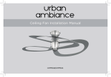
1. Juego de aspas (5)
2. Escudete superior
3. Conjunto de bola/tubo de suspensión
4. Cubridor del motor
5. Conjunto de motor del ventilador
6. Plato de montaje
7. Kit de luces LED
8. Pantalla de vidrio
9. Transmisor + soporte + 2 tornillos de montaje
10. 9 volt bateria
11. Juego de balanceo
3
1
2
10
4
9
11
5
6
7
8
12
a
b
9
V
o
l
t
B
a
t
t
e
r
y
LOW
OFF
HI
MED
REV
Cómo desembalar el ventilador 2.
12. Dos bolsas de piezas pequeñas:
a. Piezas de fijación de las aspas
(16 Tornillos, 16 Arandelas de fibra )
b. Piezas demontaje
(3 conectores plásticos para cables
eléctricos).
Desembalar el ventilador y revisar el contenido. Debe tener los siguientes elementos:
/