
Ceiling Fan Installation Manual
P257093089925_A

Date Pu rchased
Store Purchased
Model No.
Serial No.
Vendor No.
UPC
109226
P2570
Limited Lifetime Warranty
Progress Lighting fan motors are warranted to the original purchaser to be free of electrical and/or mechanical defects for so
long as the original purchaser owns the fan. Pull chain switches, reverse switches, capacitors and metal finishes are warranted to
be free from defects in materials or workmanship for a period of 1 year from the date of purchase. Warping of wooden or plastic
blades is not covered by this warranty nor is corrosion and/or deterioration of any finishes for fans installed within ten miles of
any sea coast. Extended warranties for ENERGY STAR
®
qualified products may apply.
Progress Lighting ceiling fans with built-in LED light sources, when properly installed and under normal conditions of use, are
warranted to be free from defects in material and workmanship which cause the light sources to fail to operate in accordance
with the specifications for (i) five (5) years from the date of purchase on the LED Light modules and electrical components for
fans used in single family residences, and (ii) three (3) years from the date of purchase on the LED Light modules and electrical
components for fans used in multi-family or commercial applications. LED bulbs supplied by Progress Lighting carry no
warranty other than manufacturer’s warranty. Non-LED bulbs carry no warranty.
With proof of purchase, the original purchaser may return the defective fan to the place of purchase during the first 30 days for
replacement. After 30 days, the original purchaser MUST contact Progress Lighting at (864) 678-1000 for repair or replacement
which shall be determined in Progress Lighting’s sole discretion and shall be purchaser’s sole and exclusive remedy.
Labor and Shipping Excluded. This warranty does not cover any costs or fees associated with the labor (including, but not
limited to, electrician’s fees) required to install, remove, or replace a fan or any fan parts.
This warranty shall not apply to any loss or damage resulting from (i) normal wear and tear or alteration, misuse, abuse or
neglect, or (ii) improper installation, operation, repair or maintenance by original purchaser or a third party, including without
limitation improper voltage supply or power surge, use of improper parts or accessories, unauthorized repair (made or
attempted) or failure to provide maintenance to the fan.
THE FOREGOING WARRANTIES STATE PROGRESS LIGHTING’S ENTIRE WARRANTY OBLIGATION AND
ORIGINAL PURCHASER’S SOLE AND EXCLUSIVE REMEDY RELATED TO SUCH PRODUCTS. PROGRESS
LIGHTING IS NOT RESPONSIBLE FOR DAMAGES (INCLUDING INDIRECT, SPECIAL, INCIDENTIAL OR
CONSEQUENTIAL), DUE TO PRODUCT FAILURE, WHETHER ARISING OUT OF BREACH OF WARRANTY,
BREACH OF CONTRACT, OR OTHERWISE. THIS WARRANTY IS GIVEN IN LIEU OF ALL OTHER WARRANTIES,
WHETHER EXPRESSED OR IMPLIED, INCLUDING THOSE OF MERCHANTABILITY, FITNESS FOR A PARTICULAR
PURPOSE OR NONINFRINGEMENT.
Some states do not allow limitations on how long an implied warranty lasts or the exclusion or limitations of incidental or
consequential damages, so the above limitations and exclusions may not apply to you. This warranty gives you specific rights
and you may have other rights which vary from state to state.
785247221653
785247221660
785247221646

Table of Contents
Safety Rules.....................................................................................................................................................................................
Unpacking Your Fan .......................................................................................................................................................................
Installing Your Fan ..........................................................................................................................................................................
Operating Your Transmitter ..........................................................................................................................................................
Care of Your Fan ...........................................................................................................................................................................
Troubleshooting ............................................................................................................................................................................
Specifications ................................................................................................................................................................................
1.
2.
3.
11.
13.
14.
15.

1. Safety Rules
1. To reduce the risk of electric shock, insure electricity has been turned off
at the circuit breaker or fuse box before beginning.
2. All wiring must be in accordance with the National Electrical Code and
local electrical codes. Electrical installation should be performed by a
qualified licensed electrician.
3. WARNING: To reduce the risk of electrical shock and fire, do not use
this fan with any solid-state fan speed control device.
4. WARNING: To reduce the risk of fire, electric shock, or personal injury,
mount to outlet box marked "Acceptable for Fan Support of 15.9 kg (35 lbs.)
Or Less" and use mounting screws provided with the outlet box. Most outlet
boxes commonly used for the support of light fixtures are not acceptable for
fan support and may need to be replaced. Due to the complexity of the
installation of this fan, a qualified licensed electrician is strongly
recommended.
WARNING
TO REDUCE THE RISK OF FIRE, ELECTRIC SHOCK OR PERSONAL
INJURY, MOUNT FAN TO OUTLET BOX MARKED ACCEPTABLE FOR
FAN SUPPORT.
5. The outlet box and support structure must be securely mounted and
capable of reliably supporting a minimum of 35 lbs (15.9 kg) or less.
Use only UL-listed outlet boxes marked FOR FAN SUPPORT.
6. The fan must be mounted with a minimum of 7 ft (2.1m) clearance from
the trailing edge of the blades to the floor.
7. To operate the reverse function on this fan, press the reversing button while
the fan is running.
8. Avoid placing objects in the path of the blades.
9. To avoid personal injury or damage to the fan and other items, be
cautious when working around or cleaning the fan.
10. Do not use water or detergents when cleaning the fan or fan blades. A
dry dust cloth or lightly dampened cloth will be suitable for most
cleaning.
11. After making electrical connections, spliced conductors should be
turned upward and pushed carefully up into the outlet box. The wires
should be spread apart with the grounded conductor and the
equipment-grounding conductor on one side of the outlet box.
12. Electrical diagrams are for reference only. Light kits that are not packed
with the fan must be UL Listed and marked suitable for use with the
model fan you are installing. Switches must be UL General Use
Switches. Refer to the Instructions packaged with the light kits
NOTE
READ AND SAVE ALL INSTRUCTIONS!
WARNING
TO REDUCE THE RISK OF PERSONAL INJURY, DO NOT BEND THE
BLADE ARMS (ALSO REFERRED TO AS BRACKETS) DURING
ASSEMBLY OR AFTER INSTALLATION. DO NOT INSERT OBJECTS IN
THE PATH OF THE BLADES.
WARNING
THIS PRODUCT CONTAINS CHEMICALS KNOWN TO THE STATE OF
CALIFORNIA TO CAUSE CANCER, BIRTH DEFECTS AND /OR OTHER
REPRODUCTIVE HARM. THOROUGHLY WASH HANDS AFTER
INSTALLING, HANDLING, CLEANING, OR OTHERWISE TOUCHING
THIS PRODUCT.

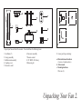
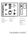
Unpack your fan and check the contents. You should have the following items:
Unpacking Your Fan 2.
10. Loose parts bag containing:
a. Blade attachment hardware
(4 screws, 4 metal washers )
b. Allen wrench
c. Mounting hardware
Wire nuts (3)
1. Fan blades (5)
2. Canopy assembly
3. Ball/downrod assembly
4. Coupling cover
5. Decorative scroll
6.
Fan motor assembly
7. Remote control
8. 12V MN21/A23 battery
9. Balancing kit
3
1
2
4
5
6
10
ac
b
7
8
9

Tools Required
Phillips screw driver, straight slot screw driver,
adjustable wrench, step ladder, and wire cutters.
Mounting Options
If there isn't an existing UL listed mounting box,
then read the following instructions. Disconnect
the power by removing fuses or turning off
circuit breakers.
Secure the outlet box directly to the building
structure. Use appropriate fasteners and building
materials. The outlet box and its support must be
able to fully support the moving weight of the
fan (at least 35 lbs). Do not use plastic outlet
boxes.
Figure 4
Figure 3
Figure 1
Figure 2
Outlet box
Outlet box
Outlet box
Note: You may need a longer downrod to
maintain proper blade clearance when installing
on a steep, sloped ceiling.
To hang your fan where there is an existing
fixture but no ceiling joist, you may need an
installation hanger bar as shown in Figure 4
(available at your Progress Lighting Retailer).
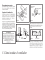
3. Installing Your Fan
WARNING
TO REDUCE THE RISK OF FIRE, ELECTRIC
SHOCK, OR OTHER PERSONAL INJURY,
MOUNT FAN ONLY TO AN OUTLET BOX
MARKED ACCEPTABLE FOR FAN SUPPORT
AND USE THE MOUNTING SCREWS
PROVIDED WITH THE OUTLET BOX. OUTLET
BOXES COMMONLY USED FOR THE
SUPPORT OF LIGHTING FIXTURES MAY NOT
BE ACCEPTABLE FOR FAN SUPPORT AND
MAY NEED TO BE REPLACED. CONSULT A
QUALIFIED ELECTRICIAN IF IN DOUBT.
Angled ceiling
maximum
17 angle
Recessed
outlet box
Provide strong support
Ceiling
hanger
bracket

4.
REMEMBER to turn off the power. Follow the
steps below to hang your fan properly.
NOTE: This ceiling fan is supplied with two types
of hanging assemblies; the standard ceiling
installation using the downrod with ball and socket
mounting, and the "close-to-ceiling" mounting.
The "close-to-ceiling" mounting is recommended
in rooms with less than 8-foot ceilings or in areas
where additional space is desired from the floor to
the fan blades.
When using the standard downrod installation, the
distance from the ceiling to the bottom of the fan
blades will be approximately 18 1/8 inches. The
"close-to-ceiling" installation reduces the distance
from the ceiling to the bottom of the fan blades to
approximately 9 inches.
Once you have decided which ceiling installation
you will use, proceed with the following
instructions. Where necessary, each section of the
instructions will note the different procedures to
follow for the two types of installation.
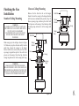
Hanging the Fan
Option 1:
Standard Ceiling Mounting
Remove the
Canopy Ring
Figure 5
Remove the canopy ring from the canopy.
(Figure 5)
1.
Remove the mounting bracket from the canopy
by loosening the four screws on the top of the
canopy. Remove the two non-slotted screws
and loosen the slotted screws. (Figure 6)
2.
Route wires exiting from the top of the fan
motor through the coupling cover, decorative
scroll, canopy cover, canopy ring, canopy and
then through the ball/ downrod. (Figure. 7)
Loosen, but do not remove the 2 set screws on
the collar on top of the motor housing.
3.
4.
Loosen but
do not Remove
Remove
Figure 6
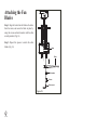
(Figure 7)
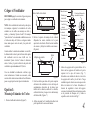
5.
6.
Figure 7
Align the holes at the bottom of the downrod
with the holes in the coupling on top of the
motor housing. (Figure 7) Carefully insert the
clevis pin through the holes in the collar and
downrod. Be careful not to jam the clevis pin
against the wiring inside the downrod. Insert
the cotter pin through the hole near the end of
the clevis pin until it snaps into its locked
position, as noted in the circle inset of Fig. 7.
Tighten two set screws on top of the fan motor
firmly. Attach the decorative scroll to the
motor housing using the screws provided.
Pin in Locked
Positioon
Motor Collar
Coupling Cover
Screws
Decorative Scroll
Motor Wires
Ball/Downrod
Assembly
Ceiling Canopy
Canopy Cover
Canopy Ring
Cotter Pin
Tighten Screw
Firmly
Clevis Pin

5.
Remove three of the six screws and lock
washers (every other one) from the collar of
top motor. (Figure 9)
Route the wires exiting the top of the fan motor
through the canopy ring (make sure the slot
openings are on top). then proceed to place the
ceiling canopy over the collar at the top of the
motor. (Figure 10)
Align the mounting holes with the holes in the
motor and fasten using the screws and lock
washers removed in step 4. (Fig. 10)
Tighten the mounting screws security.
4.
5.
6.
7.
Motor
Collar Screw and Lock Washer
(3 of 6 Places)
Figure 9
Option 2:
Close-to-Ceiling Mounting
Remove the canopy ring from the canopy.
(Figure 5)
Remove the mounting bracket from the canopy
by loosening the four screws on the top of the
canopy. Remove the two non-slotted screws
and loosen the slotted screws. (Figure 6)
Remove the decorative canopy bottom cover
from the canopy by turning the canopy bottom
cover counterclockwise. (Figure 8)
1.
2.
3.
Canopy
Bottom
Cover
Remove
Figure 8
Figure 10
Collar
Ceiling
Canopy
Screw and
Lock Washer
(3 Places)
Canopy Ring
NOTE: If a longer downrod is needed, take out
the screw located in the hanger ball, lower the
hanger ball and remove the pin, remove all 3
pieces from the downrod and assemble them onto
the new longer downrod before proceeding step 3.
(The longer downrod is available at any Progress
Lighting retailer)
WARNING
FAILURE TO PROPERLY INSTALL
CLEVIS PIN AS NOTED IN STEP 5
COULD RESULT IN FAN LOOSENING
AND POSSIBLY FALLING.
WARNING
FAILURE TO COMPLETELY TIGHTEN
THE THREE SCREWS IN STEP 7 COULD
RESULT IN FAN LOOSENING AND
POSSIBLY FALLING.

6.
WARNING
WHEN USING THE STANDARD BALL/
DOWNROD MOUNTING. THE TAB IN THE
RING MUST REST IN THE GROOVE OF THE
HANGER BALL. FAILURE TO PROPERLY SEAT
THE TAB IN THE GROOVE COULD CAUSE
DAMAGE TO WIRING.
WARNING
THE TAB AS SHOWN IN FIGURE 12 IS ONLY
TO BALANCE THE FAN WHILE ATTACHING
WIRING. FAILURE TO HANG AS SHOWN IN
FIGURE 12 MAY RESULT IN TAB BREAKING
CAUSING THE FAN TO FALL. TAB MUST PASS
FROM INSIDE TO OUTSIDE OF CANOPY.
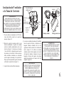
Installing Fan to
the Electrical Box
Figure 11
Carefully lift the fan assembly up to the ceiling
mounting bracket and hang the fan on the tab
provided by utilizing one of the holes at the outer
rim of the ceiling canopy. (Figure 12) If use
standard mounting, seat the hanger ball in the
mounting bracket socket. Make sure the tab on
the mounting bracket socket is properly seated in
the groove in the hanger ball. (Figure 12)
4.
Pass the 120-volt supply wires through the
center hole in the mounting bracket. (Figure 11)
Attach the mounting bracket on the outlet box
by sliding the mounting bracket over the screws
provided with the outlet box. (Figure 11) When
using “close-to-ceiling” mounting, it is
important that the mounting bracket be level. If
necessary, use leveling washers (not included)
between the mounting bracket and the outlet
box. Note that the flat side of the mounting
bracket is toward the outlet box. (Figure 11)
Securely tighten the two mounting screws.
1.
2.
3.
Figure 12
Groove
Standard Mounting
Close-to-Ceiling Mounting
Tab
CUL Listed
Outlet Box
Ceiling Mounting
Bracket
Mounting
Screws (Supplied
with Outlet Box)
120V
Wires
WARNING
TO REDUCE THE RISK OF FIRE, ELECTRIC
SHOCK OR OTHER PERSONAL INJURY. MOUNT
FAN ONLY TO AN OUTLET BOX OR
SUPPORTING SYSTEM MARKED ACCEPTABLE
FOR FAN SUPPORT AND USE THE MOUNTING
SCREWS PROVIDED WITH THE OUTLET BOX.

7.
Make the Electric
Connections
WARNING: To avoid possible electrical shock,
be sure electricity is turned off at the main fuse box
before wiring.
Step 1. Motor to House Supply Wires Electrical
Connections: Connect the WHITE wire (Neutral)
from the outlet box to the WHITE wire marked
"AC in N" from the motor. (Fig. 13)
Step 2. Connect the BLACK wire (Hot) from the
outlet box to the BLACK wire marked "AC in L"
from the motor. (Fig. 13)
Secure all wire connections with the plastic wire
nuts provided.
Figure 13
Outlet Box
Black ("AC IN L")
White ("AC IN N")
White (Neutral)
Black (Hot)
Green or bare
copper (ground)
Ground (green)
(Connect to ground
wire on hanger
bracket if no house
ground wire exists.)

8.
WARNING
MAKE SURE THE TAB ON THE HANGING
BRACKET PROPERLY SITS IN THE GROOVE IN
THE HANGER BALL BEFORE ATTACHING THE
CANOPY TO THE BRACKET BY TURNING THE
HOUSING UNTIL IT DROPS INTO PLACE.
WARNING
LOCKING SLOTS OF CEILING CANOPY ARE
PROVIDED ONLY AS AN AID TO MOUNTING.
DO NOT LEAVE FAN ASSEMBLY
UNATTENDED UNTIL ALL FOUR CANOPY
SCREWS ARE ENGAGED AND FIRMLY
TIGHTENED.
Figure 14
Canopy
Outlet Box
Hanger
Bracket
Groove
Tab
Screws
Canopy
Ring
Canopy
Outlet Box
Hanger
Bracket
Screws
Canopy
Ring
Figure 15
Finishing the Fan
Installation
Standard Ceiling Mounting
Slide canopy up to the ceiling as shown in Figure
14. Make sure you place the wires safely into the
outlet box. Secure the canopy to the hanger
bracket with the four screws with your fan. Raise
up canopy ring and line up the 4 tabs with the 4
grooves on the canopy. Once lined up, slide the
canopy ring and secure it to the canopy until snug.
Remove the fan from the tab on the hanger
bracket. Secure the canopy to the hanger bracket
with four screws included with your fan. (Fig. 15)
Raise up canopy ring and line up the 4 tabs with
the 4 grooves on the canopy. Once lined up, slide
the canopy ring and secure it to the canopy until
snug.
Close-to-Ceiling Mounting

9.
Attaching the Fan
Blades
Step 1. Align the holes from the blade to the holes
from the motor, and secure the blade in place by
using the screws and metal washers with the allen
wrench provided. (Fig. 16)
Step 2. Repeat this process to attach the other
blades. (Fig. 16)
Figure 16
Motor
Blade
Screws
Allen wrench
Metal washer

Blade Balancing
All blades are grouped by weight. Because
natural woods very in density, the fan may
wobble even though the blades are weighed
equally.
The following procedure should correct most
fan wobbling problems. Check after each step.
1. Check that all blade and blade arm screws are
secure.
2. Most fan wobbling problems are caused
when blade levels are unequal. Check this
level by selecting a point on the ceiling
above the tip of one of the blades. Measure
this distance as shown in Figure 17. Rotate
the fan until the next blade is positioned for
measurement. Repeat for each blade. The
distance deviation should be equal within
1/8".
3. Use the enclosed Blade Balancing Kit if the
blade wobble is still noticeable.
4. If the blade wobble is still noticeable,
interchanging two adjacent (side by side)
blades can redistribute the weight and
possibly result in smoother operation.
Touching
ceiling
Figure 17
WARNING
TO REDUCE THE RISK OF PERSONAL
INJURY, DO NOT BEND THE BLADE
HOLDERS WHILE INSTALLING,
BALANCING THE BLADES, OR CLEANING
THE FAN. DO NOT INSERT FOREIGN
OBJECTS BETWEEN ROTATING FAN
BLADES.
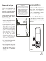
10.
Installing the battery
Your DC brushless motor is equipped with an
automatically learned type remote control. Restore
power to ceiling fan and test the transmitter as below
for proper operation. (Fig. 18)
Install a 12V MN21/A23 battery (included) into the
remote control. To prevent damage to the remote
control, remove the battery if not used for long
periods. (Fig. 18)
Figure 18
ON ECE
1234
ON
D
ON ECE
ON
D

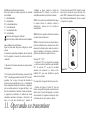
11. Operating Your Transmitter
NOTE: If the self calibration test failed, turn the AC
power off; restore power and process the self
calibration test again.
NOTE: During self calibration test, the remote is
non-fuctional.
NOTE: The learning frequency function and self
calibration test will continue to retain the last set
frequency and calibration set even when the AC
power is shut off. If the frequency is changed the self
calibration test will occur again.
“D” and “ON” dip switch:
1. The “ON” selection is the light dimmable selection
and is to be used with all bulbs except for CFL bulbs.
The “D” selection is the light ON only (no dimming
function) and is to be used with CFL bulbs as CFL
bulbs in most cases cannot be used with dimming
controllers.
This receiver provides the following protective
function:
1. Lock Rotor Position: The DC motor has a built-in
safety against a stalled or locked rotor condition
(stalled blade rotation). If there is an obstruction or
fault with the motor, the current monitoring function
will automatically turn power off to the motor after 30
seconds. Remove the obstruction and turn the AC
power off. Restore power and re-start fan motor.
2. Over 80W protection: When the receiver detects
motor power consumption which is greater than 80W,
the receiver power will be stopped and operation will
immediately discontinue. Wait for 5 seconds and then
turn the receiver power back on.
Remote Control Button Definitions:
These six buttons are used to set the fan speed as
follows:
I = minimum speed
II = low speed
III = medium low speed
IV = medium speed
V = medium high speed
VI = high speed
button: Turns the fan off.
button: Controls fan direction.
Setting the Remote Control
Follow the below steps to set the remote control:
The auto learning function will only mandate within 60
seconds when turning the fan’s AC power ON.
1. Select desired frequency from the back of transmitter.
2. From the back of the transmitter, press the “SET”
button, and hold the “SET” button for over 5 seconds.
Once the receiver has detected the frequency, the light
will flash twice, and the fan will automatically begin to
operate and start to rotate in the counterclockwise
direction and on the highest RPM for 3 minutes. When
counterclockwise rotation has finished, the fan will
automatically reverse to clockwise direction again to the
highest RPM for 3 minutes. Fan will shut off when the
self calibration test has finished. The total self
calibration test will last about 6 minutes.
Figure 19

Speed settings for warm or cool weather depend on
factors such as the room size. Ceiling height, number
of fans and so on.
NOTE: To operate the reverse function on this fan,
press the reverse button while the fan is running.
Warm weather - (Forward) A downward airflow
creates a cooling effect as shown in Fig. 20. This
allows you to set your air conditioner on a warmer
setting without affecting your comfort.
Cool weather - (Reverse) An upward airflow moves
warm air off the ceiling area as shown in Fig. 21. This
allows you to set your heating unit on a cooler setting
without affecting your comfort.
Figure 20
Figure 21
12.

Here are some suggestions to help you maintain your
fan
1. Because of the fan's natural movement, some
connections may become loose.
Check the support
connections, brackets, and blade attachments
twice a year.
Make sure they are secure.
(It is not
necessary to remove fan from ceiling.)
2. Clean your fan periodically to help maintain its new
appearance over the years. Use only a soft brush or
lint-free cloth to avoid scratching the finish. The
plating is sealed with a lacquer to minimize
discoloration or tarnishing. Do not use water when
cleaning. This could damage the motor, or the wood,
or possibly cause an electrical shock.
3. You can apply a light coat of furniture polish to the
wood blades for additional protection and enhanced
beauty. Cover small scratches with a light application
of shoe polish.
4.
There is no need to oil your fan.
The motor has
permanently lubricated bearings.
IMPORTANT
MAKE SURE THE POWER IS OFF AT THE
ELECTRICAL PANEL BOX BEFORE YOU
ATTEMPT ANY REPAIRS. REFER TO THE
SECTION "MAKING ELECTRICAL
CONNECTIONS"
13.
Care of Your Fan

Troubleshooting
14.
Solution
1. Check circuit fuses or breakers.
2. Check line wire connections to the fan and switch wire connections in the switch housing.
CAUTION: Make sure main power is off.
3. Check to make sure the dip switches from the transmitter and receiver are set to the same frequency.
1. Make sure all motor housing screws are snug.
2. Make sure the screws that attach the fan blade bracket to the motor hub is tight.
3. Make sure wire nut connections are not rubbing against each other or the interior wall of the switch housing.
CAUTION: Make sure main power is off.
4. Allow a 24-hour "breaking-in" period. Most noise associated with a new fan disappear during this time.
5. If using an optional light kit, make sure the screws securing the glassware are tight. Check that light bulb is also secure.
6. Some fan motors are sensitive to signals from solid-state variable speed controls. If you have installed this type of control,
choose and install another type of control.
7. Make sure the upper canopy is a short distance from the ceiling. It should not touch the ceiling.
1. Do not connect the fan with wall mounted variable speed control (s).
2. Make sure the dip switches are set correctly.
Problem
Fan will not start.
Fan sounds noisy.
Remote control
malfunction

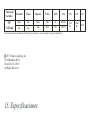
15.
Specifications
2017 Progress Lighting, Inc.
701 Millennium Blvd.,
Greenville, SC 29607
All Rights Reserved
c
17.41
lbs
19.84
lbs
2.10'
Fan Size Speed
Volts
Amps
Watts
RPM
CFM
N.W. G.W. C.F.
56"
Low
High
120
120
These are approximate measures. They do not include Amps and Wattage used by the light kit.
0.046
0.43
2.08
32.67
53
159
1951.56
6767.71

Manual de Instalación del Ventilador de Techo
P257093089925_A

Fecha de compra
Lugar de compra
N de modelo.
N de serie
Numero de vendedor
UPC
Garantía limitada de por vida
Se garantiza al comprador original que los motores de los ventiladores de Progress Lighting no presentan defectos mecánicos o
eléctricos por el tiempo durante el cual el comprador original sea dueño del ventilador. Los interruptores de cadena, interruptores
de reversa, capacitores y acabados de metal cuentan con garantía libre de defectos de materiales o mano de obra por 1 año a partir
de la fecha de compra. La deformación de las aspas de plástico o madera no está cubierta por esta garantía, así como tampoco la
corrosión y/o el deterioro de los acabados en el caso de los ventiladores instalados dentro de un radio de 10 millas (16 km) de la
costa del mar. Pueden corresponder garantías extendidas para los productos que cumplen con los requisitos de ENERGY STAR®.
Los ventiladores de techo Progress Lighting con fuentes de iluminación LED incorporadas, cuando se los instala debidamente y
bajo condiciones de uso normales, están garantizados como libres de defectos de materiales y mano de obra que hacen que las
fuentes de iluminación dejen de funcionar de acuerdo con las especificaciones durante (i) cinco (5) años a partir de la fecha de
compra para los módulos de luces LED y los componentes eléctricos para los ventiladores utilizados en residencias unifamiliares,
y (ii) tres (3) años a partir de la fecha de compra para los módulos de luces LED y los componentes eléctricos para los
ventiladores utilizados en aplicaciones comerciales o multifamiliares. Los focos LED suministrados por Progress Lighting no
cuentan con garantía más allá de la garantía del fabricante. Los focos que no son LED no cuentan con garantía.
Con comprobante de compra, el comprador original podrá devolver el ventilador defectuoso al lugar de compra, durante los
primeros 30 días, para su reemplazo. Pasados los 30 días, el comprador original DEBE contactarse con Progress Lighting al (864)
678-1000 para la reparación o el reemplazo, que se determinará a criterio exclusivo de Progress Lighting y será la compensación
única y exclusiva del comprador.
Se excluye la mano de obra y el envío. Esta garantía no cubre los costos o cargos asociados con la mano de obra (incluidos, entre
otros, los honorarios del electricista) necesaria para instalar, quitar o reemplazar el ventilador o cualquiera de sus partes.
Esta garantía no se aplicará a ninguna pérdida o daño que resulte del (i) uso y desgaste normales o de una alteración, uso indebido
o descuido, o de la (ii) instalación, operación, reparación o mantenimiento inadecuados por parte del comprador original o de un
tercero, incluidos, entre otros, suministro de voltaje inadecuado o sobrecarga eléctrica, uso de piezas o accesorios inadecuados,
reparación no autorizada (realizada o que se intentó realizar) o falta de mantenimiento al ventilador.
LAS GARANTÍAS PRECEDENTES ESTABLECEN LA OBLIGACIÓN DE GARANTÍA COMPLETA DE PROGRESS LIGHTING Y LA
COMPENSACIÓN ÚNICA Y EXCLUSIVA DEL COMPRADOR ORIGINAL EN RELACIÓN CON DICHOS PRODUCTOS. PROGRESS
LIGHTING NO ASUME RESPONSABILIDAD POR DAÑOS (INCLUIDOS INDIRECTOS, ESPECIALES, INCIDENTALES O
EMERGENTES), DEBIDO A FALLAS DEL PRODUCTO, YA SEA QUE SURJAN DEL INCUMPLIMIENTO DE LA GARANTÍA, DEL
INCUMPLIMIENTO CONTRACTUAL O DE OTRO MODO. ESTA GARANTÍA REEMPLAZA CUALQUIER OTRA GARANTÍA, YA SEA
EXPRESA O IMPLÍCITA, INCLUSO AQUELLAS DE COMERCIABILIDAD, IDONEIDAD PARA UN FIN EN PARTICULAR O NO
INCUMPLIMIENTO.
Algunos estados no permiten limitaciones sobre la duración de una garantía implícita o la exclusión de limitaciones de daños
incidentales o emergentes, de modo que las limitaciones y exclusiones anteriores tal vez no se apliquen a su caso. La presente
garantía le otorga derechos específicos y es posible que usted tenga otros derechos que varían según el estado.
P2570
785247221653
785247221660
785247221646
109226
Page is loading ...
Page is loading ...
Page is loading ...
Page is loading ...
Page is loading ...
Page is loading ...
Page is loading ...
Page is loading ...
Page is loading ...
Page is loading ...
Page is loading ...
Page is loading ...
Page is loading ...
Page is loading ...
Page is loading ...
Page is loading ...
-
 1
1
-
 2
2
-
 3
3
-
 4
4
-
 5
5
-
 6
6
-
 7
7
-
 8
8
-
 9
9
-
 10
10
-
 11
11
-
 12
12
-
 13
13
-
 14
14
-
 15
15
-
 16
16
-
 17
17
-
 18
18
-
 19
19
-
 20
20
-
 21
21
-
 22
22
-
 23
23
-
 24
24
-
 25
25
-
 26
26
-
 27
27
-
 28
28
-
 29
29
-
 30
30
-
 31
31
-
 32
32
-
 33
33
-
 34
34
-
 35
35
-
 36
36


Progress Lighting P2570-143 Installation guide
- Category
- Household fans
- Type
- Installation guide
Ask a question and I''ll find the answer in the document
Finding information in a document is now easier with AI
in other languages
Related papers
-
Progress Lighting P2548-2030K Installation guide
-
-
-
-
-
Progress Lighting P250075 User manual
-
-
-
Progress Lighting P250095 User manual
-
Other documents
-
 urban ambiance UHP9053 Installation guide
-
 urban ambiance UHP9052 Installation guide
-
 urban ambiance UHP9051 Installation guide
-
 urban ambiance UHP9050 Installation guide
-
 urban ambiance UHP9201 Installation guide
-
 urban ambiance UHP9200 Installation guide
-
 urban ambiance UHP9160 Installation guide
-
 urban ambiance UHP9060 Installation guide
-
 urban ambiance UHP9062 Installation guide
-
 urban ambiance UHP9061 Installation guide


