Page is loading ...

RE926X_Flexible Bus WiFi Communicator Page 1 of 8 10-Mar-15
24-hour Tech Support: (715)808-0164
www.ResolutionProducts.com
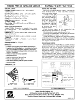
A /Rx
CL K
B /Tx
DA TA
GN D
+1 2V
Honeywell
Vista 20P or 15P
DATA O UT 7
DATA IN 6
AUX + 5
AUX - 4
Gre e n
Y el low
Re d
Bla c k
RE926X
WiFi
Mo d ule
RE926X Flexible Bus WiFi Communicator
Features
• Connects panels to local WiFi Network
• Compatible with:
o Honeywell Vista® 15P and 20P
o DSC PowerSeries®
o Future: UTC NX, UTC Concord
• Enables:
o Alarm Reporting
o Interactive Control Functions
o Ethernet data reliability
o Z-Wave Communicator included
Key Instructions
• The same unit works for Vista & DSC PowerSeries
[Future: UTC NX, and UTC Concord].
• Selectable switch determines panel compatibility.
• DO NOT MOUNT INSIDE METAL CAN – there are radios on the boards that
need to be in free-air to communicate.
• Communicator must be connected to a 12V nominal power supply with
battery backup, such as the control panel's aux power output.
• RE926X communicates with the Vista 15P/20P via AUI device 2.
Enable AUI 2 in the Vista.
Wiring Instructions
NOTE:
Some programming must be done PRIOR to connection
Maximum cable lengths shown in the table below, this assumes the communicator is
the only device attached to the cable. If multiple devices share the same cable, the
maximum cable length must be derated accordingly.
Wire Size (AWG) Maximum cable length to Control Panel
18 600
22 250
24 150
DSC
PowerSeries
Y EL
GRN
AUX - BLK
AUX + RED
Gre e n
Y el low
Re d
Black
RE926X
WiFi
M od ul e
A /Rx
CL K
B /Tx
DA TA
GN D
+1 2V
RE926X_Flexible Bus WiFi Communicator Page 2 of 8 10-Mar-15
24-hour Tech Support: (715)808-0164
www.ResolutionProducts.com
Vista 20P and Vista 15P Programming:
Compatible Honeywell Panels:
Vista 20P (version 3.0 or later) (controls partition 1 only)
Vista 15P (version 3.0 or later)
1) Refer to server setup instructions and set up the account on the Dealer
Portal.
2)
Be sure to add a contact that uses the system MASTER CODE to the account before
connecting the module. This will ensure the module can properly communicate
with and configure required system settings.
3) Disarm the system (all partitions).
4) The RE926X automatically communicates with the Vista using AUI device 2.
The panel is probably defaulted to this. If not, enable AUI 2 in the *189 field.
5) Power down the Vista system.
6) Set RE926X panel selector switch to Honeywell: DSC CDX HW UTC
7) Connect the Vista and RE926X as shown in the Wiring Instructions above.
8) Apply power to the Vista 15P/20P system.
The Vista control panel will begin automatic configuration.
Can move to Step 8 during this…
9) WiFi Protected Setup connection to Router (see Operation – WiFi Protected
Setup connection to Router)
10) The module will automatically connect itself to the server, and then enable
the following settings automatically:
IP/GSM device (*29)
Communicate to IP/GSM device first (*55)
Test Report off (*64)
Opening Report (*65)
Closing reports (*66)
Alarm cancel report (*68)
AC Power restoral report (*73)
Low Battery restoral report (*74)
Phone Monitor off (*92)
11) Finally, the keypad(s) should display "DISARMED Ready to Arm".
12) Installation is complete.

RE926X_Flexible Bus WiFi Communicator Page 3 of 8 10-Mar-15
24-hour Tech Support: (715)808-0164
www.ResolutionProducts.com
DSC Power Series Programming:
Compatible DSC Panels:
PC580 (Power 432) PC5020 (Power 864)
PC1555 (Power 632) PC1616
PC1555MX (Power 632) PC1832
PC5010 (Power 832) PC1864
PC5015 (Power 832)
1) Refer to server setup instructions and set up the account on the Dealer
Portal.
2) Be sure to add a contact that uses the system MASTER CODE to the account before
connecting the module. This will ensure the module can properly communicate
with and configure required system settings.
3) Using the system’s Installer Code:
a) Disable the Communicator ([380]:[1])
b) Disable the Telephone Line Monitor ([015]:[7])
c) Delete Telephone Numbers (programming section 301-303)
d) Verify Alt Comm ([351]:[5]) is enabled
4) Verify Alarm report codes are setup properly for zones that are being used,
1-64 (programming section 320-349). System will report as Burg(130) if
programmed as FF.
5) If using Aux input (PGM2) verify Aux input report codes are setup properly
(Programming section 329:4). System will report as Fire (110) if
programmed as FF.
6) To enable reporting of the Period Test Transmission, program the “periodic
Test Transmission” ([348]:[4]) and the “Periodic Test Transmission with
Trouble” ([348]:[3]) reporting codes to “02”
7) All other reports are hardcoded in the gateway and cannot be changed
regardless of what is entered in the programmed location.
8) Format and account number have no effect on reporting.
9) Disarm the system (all partitions)
10) Power down the DSC system.
11) Set RE926X panel selector switch to DSC: DSC CDX HW UTC
12) Connect the DSC Panel and RE926X as shown in the Wiring Instructions
above.
13) Apply power to the DSC system.
14) The DSC control panel will begin automatic configuration. Can move to step
14 during this time…
15) WiFi Protected Setup connection to Router (see Operation – WiFi Protected
Setup connection to Router)
16) Installation complete.
RE926X_Flexible Bus WiFi Communicator Page 4 of 8 10-Mar-15
24-hour Tech Support: (715)808-0164
www.ResolutionProducts.com
Reporting Codes for DSC panels:
The following table shows all events reported when connected to a DSC Panel.
Event
Report Code
AC Fail/Restore
301
Panel Low Battery/Low Battery Restore
302
Opening/Closing Report
400
Cancel Report
406
Zone Alarm
See below
keypad fire panic
110
keypad aux panic
100
keypad police panic
120
D
uress
121
Periodic Test Transmission
602
Periodic Test with Trouble Transmission
608
Automatic Contact ID is not supported. Manually programmed reporting codes
are only supported for alarms on zones 1-64 ([320] – [324]) and for alarms on
the PGM2/Aux input ([329]:[4]). The PGM2/Aux input is reported as zone
number 99.
If Report Codes have not been manually programmed for zone alarms, zone
alarm reporting codes default to:
• Any zone alarm (zones 1-64): Code 1130 (Burglary)
• PGM2/Aux input (zone 99, likely a 2-wire Smoke): Code 1110 (Fire)
Be sure to verify that all codes are being properly reported to the central
station after you have installed the communicator module or modified any
reporting program settings in the DSC installer programming menu.
Trouble Shooting the Panel Connection:
If the “CS” or “Platform” LEDs are blinking, here are possible
problems:
Incorrect wiring
Incorrect panel switch position
Unsupported panel version
Unsupported panel model
Panel is in Installer Program mode
Vista Specific:
AUI not enabled
AUI used for some other function
LRR not enabled
Another LRR or IP/GSM device connected to panel bus
Factory Default Button and WPS button
a) Holding the Factory Default button for 5 seconds will reset the RE926X Communicator
b) Holding the Factory Default button for 10 seconds (LEDs will flash off
twice) will set the RE926X to factory defaults
c) Press and Release the WPS button (WiFi Led flashes slowly) for
connecting Primary Router
d) Press and Hold the WPS until WiFi LED flashes rapidly for connecting to Backup Router
e) Press and Hold the Factory Default button, then pressing the WPS button
for approximately one second (Wifi LED will flash) to put the
communicator into Access Point mode

RE926X_Flexible Bus WiFi Communicator Page 5 of 8 10-Mar-15
24-hour Tech Support: (715)808-0164
www.ResolutionProducts.com
Operation
Event Reporting:
Events are reported to both the monitoring receiver and the interactive server. All
events use Contact ID reporting codes. The following events are reported by
default:
Alarms System Low Battery
Alarm cancels System Low Battery Restoral
Openings AC Power Fail (0-4 hour random delay)
Closings AC Power Restoral (0-4 hour random delay)
Vista Only:
Additional events can be enabled for reporting if desired, by enabling
the desired event reports in system programming.
Interactive Control:
The system may be controlled remotely through the interactive platform.
The arm/disarm control and status applies to partition 1 only.
Z-Wave
Z-Wave devices can be controlled via the Interactive function.
Siren (Future capability)
Resolution Wireless Siren will be useable to indicate alarm and statuses.
WiFi Protected Setup Connection to Router:
A) Connection to Backup router:
• This Backup router is optional. If no Backup is required, skip to step B.
• Press & hold Communicator’s WPS button, until WiFi LED blinks rapidly.
• Press & release Backup Router’s WPS button.
• WiFi LED is steady when fully connected to Backup Router.
B) Connection to Primary router:
• Press & release Communicator’s WPS button, until WiFi LED blinks slowly.
• Press & release Primary Router’s WPS button.
• WiFi LED is steady when fully connected to Backup Router.
C) Manually Setting WiFi Parameters
1. Download the mobile app from http://esmarthome.protection1.com/downloads/
(Note: this app will only work on Android handsets, running versions 4.2 or later)
2. Reset the communicator to factory defaults.
3. Put the communicator into Access Point mode. (see Factory Default button and
WPS button section)
4. Start the mobile app, and connect the mobile device to the Communicator’s
Access Point WiFi network – ResProd+the last 6 digits of the Mac address.
(Ex – ResProdF0009A then press back to continue.)
5. Select the customers SSID from the list
6. Enter the WiFi password and click the submit button.
7. You should see a prompt confirming the settings were successfully pushed to the
communicator. If not, wait ten seconds; settings may have been pushed anyway.
8. Confirm successful connection by seeing the WiFi LED on, followed by the CS,
and Platform LED turning on. This may take up to 30 seconds.
RE926X_Flexible Bus WiFi Communicator Page 6 of 8 10-Mar-15
24-hour Tech Support: (715)808-0164
www.ResolutionProducts.com
LEDs
Bus Board LEDs
Indication
Green
On when the board is powered and running
Red
Vista: Flickers occasionally when module talks to the panel
DSC: Flickers continuously to indicate communication with the DSC panel
WiFi Card LEDs
Indication
Power
(Green)
ON and Flashing once per second when the board is powered and running
WiFi
(Red)
ON when the unit is registered with the local WiFi router
CS
(Red)
ON
when the connection to the
central station is established
Flashes when there is a probl
em detecting the Panel type
Platform
(Amber)
ON w
hen the connection to the Panel
a
nd connection to the
interactive
server is established
Flashes when there is a problem communicating with the panel
Picture
Z
-
Wave
Module
Panel
Selector
Switch
Data Bus
Connector
Board Revision
see
Revision Functionality
Table
Z
-
Wave
Antenna
WPS
Button
Factory
Default
Button

RE926X_Flexible Bus WiFi Communicator Page 7 of 8 10-Mar-15
24-hour Tech Support: (715)808-0164
www.ResolutionProducts.com
Specifications
Current Draw: 110 mA Nominal
Temperature Range: 0F to 120F
Housing dimensions: 4x6x1 inches
Specifications subject to change without notice.
Revision Functionality Table
Revision on board
Functionality
57
-
0055
-
02 RevA00
Vista15P/20P Compatibility Only
57
-
0
055
-
02 RevA01
added P1 Vista W320P1 Compatibility
57
-
0055
-
02 RevA02
Or Later
Vista 15P / 20P & DSC PowerSeries
Compatibility
Notices
“GE”, “Honeywell”, “DSC”, “2GIG” and “Napco” are trademarks owned by General Electric
Company, Honeywell International Inc., Tyco Safety Products Canada LTD, 2GIG Technologies
Inc., and NAPCO Security Systems, Inc., respectively.
Resolution Products, Inc. products will function with one of either GE, Honeywell, DSC or
Napco systems. However, no Resolution product is produced by, endorsed by, nor is officially
associated with GE, Honeywell, DSC or Napco. Resolution recommends verifying proper
enrollment and operation, per control panel installation instructions, at installation.
Warranty
Resolution Products, Inc. will replace products that are defective in their first five (5) years.
RE926X_Flexible Bus WiFi Communicator Page 8 of 8 10-Mar-15
24-hour Tech Support: (715)808-0164
www.ResolutionProducts.com
FCC Notice
This device complies with Part 15 of the FCC rules. Operation is subject to the
following two conditions:
(1)This device may not cause harmful interference.
(2)This device must accept any interference that may be received, including
interference that may cause undesired operation.
Changes or modifications not expressly approved by the Resolution Engineering, Inc.
could void the user's authority to operate this equipment.
FCC ID: U5X-RE926
This device contains FCC ID: W7OMRF24WG0MAMB
This equipment has been tested and found to comply with the limits for a Class B digital device,
pursuant to part 15 of the FCC Rules. These limits are designed to provide reasonable protection
against harmful interference in a residential installation. This equipment generates, uses and can
radiate radio frequency energy, and if not installed and used in accordance with the instructions,
may cause harmful interference to radio communications. However, there is no guarantee that
interference will not occur in a particular installation. If this equipment does cause harmful
interference to radio or television reception, which can be determined by turning the equipment
off and on, the user is encouraged to try to correct the interference by one or more of the
following measures:
(1)Reorient or relocate the receiving antenna.
(2)Increase the separation between the equipment and receiver.
(3)Connect the equipment into an outlet on a circuit different from that to which the
receiver is connected.
(4)Consult the dealer or an experienced radio/TV technician for help.
RF Exposure:
To satisfy FCC RF Exposure requirements for mobile and base station transmission
devices, a separation distance of 20 cm or more should be maintained between the
antenna of this device and persons during operation. To ensure compliance, operation
at closer than this distance is not recommended.
The antenna(s) used for this transmitter must not be co-located or operating in
conjunction with any other antenna or transmitter.
IC Notice
This device complies with Industry Canada license-exempt RSS standard(s). Operation is
subject to the following two conditions:
(1)This device may not cause interference, and
(2)This device must accept any interference, including interference that may cause
undesired operation of the device.
Le présent appareil est conforme aux CNR d'Industrie Canada applicables aux appareils
radio exempts de licence. L'exploitation est autorisée aux deux conditions suivantes :
(1)l'appareil ne doit pas produire de brouillage, et
(2)l'utilisateur de l'appareil doit accepter tout brouillage radioélectrique subi,
même si le brouillage est susceptible d'en compromettre le fonctionnement.
Model: RE926X
IC: 8310A-RE926
This device contains IC: 7693A-24WG0MAMB
Under Industry Canada regulations, this radio transmitter may only operate using an antenna of a type
and maximum (or lesser) gain approved for the transmitter by Industry Canada. To reduce potential radio
interference to other users, the antenna type and its gain should be so chosen that the equivalent
isotropically radiated power (e.i.r.p.) is not more than that necessary for successful communication.
Conformément à la réglementation d'Industrie Canada, le présent émetteur radio peut fonctionner avec
une antenne d'un type et d'un gain maximal (ou inférieur) approuvé pour l'émetteur par Industrie Canada.
Dans le but de réduire les risques de brouillage radioélectrique à l'intention des autres utilisateurs, il faut
choisir le type d'antenne et son gain de sorte que la puissance isotrope rayonnée équivalente (p.i.r.e.)
ne dépasse pas l'intensité nécessaire à l'établissement d'une communication satisfaisante.
/