Page is loading ...

SensorVision® Systems
SpeedDome
Quick Reference Guide
Part of SpeedDome Installation and Service Manual,
8000-0518-01, REV. C.

TABLE OF CONTENTS
Quick Reference Guide: Part I
INDOOR MOUNTS
• Hard Mount Installation..................................................................................................Q-1
• Hard Mount w/Adj. Bracket Installation..........................................................................Q-2
• 2x2 Tile Mount Installation .............................................................................................Q-4
• Pendant Mount (Standard) Installation ..........................................................................Q-6
• Pendant Mount (I-Beam) Installation..............................................................................Q-7
• Chassis Installation........................................................................................................ Q-8
OUTDOOR MOUNTS
• Over Roof Mount Installation........................................................................................ Q-10
• Wall Mount–Corner Bracket Installation....................................................................... Q-12
• Pole Mount Installation................................................................................................. Q-14
• Ceiling Mount Installation............................................................................................. Q-15
• Housing and Chassis Installation................................................................................. Q-16
INDOOR/OUTDOOR
• Fixed Camera Installation ............................................................................................ Q-18
• Cable Conversions.......................................................................................................Q-19
Quick Reference Guide: Part II
FAULT ISOLATION CHECKLISTS
• Video But No Dome Response / Control ..................................................................... Q-21
• Video / Dome Control But Status Incorrect.................................................................. Q-22
• Loss of Lens Function.................................................................................................. Q-23
• Loss of All Lens Functions ........................................................................................... Q-24
• No Tilt Function ............................................................................................................Q-25
• No Pan Function / Continuous Pan .............................................................................. Q-26
• No Video But All Functions Work .................................................................................Q-27
• Poor Video But All Functions Work .............................................................................. Q-28
• Picture Too Light or Too Dark ...................................................................................... Q-29
• Dome Targeting Incorrect............................................................................................ Q-30
• Dead Dome.................................................................................................................. Q-31
REPLACEMENT PARTS
• Dome CPU Board ........................................................................................................ Q-33
• RS422 Interface Board ................................................................................................ Q-34
• CameralLens Board..................................................................................................... Q-35
• Monochrome Camera.................................................................................................. Q-36
• Color Camera............................................................................................................... Q-37
• Pan, Tilt, Zoom, Iris, and Focus Motors ....................................................................... Q-38
• Clock-Spring Cable ..................................................................................................... Q-39
• Slip-Ring ...................................................................................................................... Q-40
• Power Supply............................................................................................................... Q-41
ADJUSTMENTS
• Back Focus .................................................................................................................. Q-43
• Imager Head Cable ..................................................................................................... Q-44
COMPONENT INTERCONNECTIONS
• Component Interconnections....................................................................................... Q-45
PIN-TO-PIN WIRING
• Pin-to-Pin Wiring .......................................................................................................... Q-46

Sensormatic
SENSORVISION SYSTEMS
SENSORVISION SpeedDome Q-1
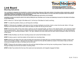
Using an S-hook, hang safety chain [d]
from a strong ceiling member and, using
a second S-hook, attach other end of the
chain to the eyebolt. Keep the chain as
taut as possible. Tighten both ends of
each S-hook.
3.
KEEP CHAIN AS TAUT AS
POSSIBLE! CLOSE ENDS
OF EACH S-HOOK!
DO NOT USE SPRINKLER
OR FIRE CONTROL
SYSTEM SECURING THE
SAFETY CHAIN!
With the three mounting tabs [f] of the
housing in the up position, insert the
housing into the ceiling hole, then from
inside the housing bring the tabs down
and tighten their screws to secure. The
housing is now ready for chassis
installation (page Q-8).
Feed video and multiconductor cables [e]
through one of the two holes in the side of
the housing. Then cover all openings in
the housing with the aluminum tape
supplied.
4.
5.
Procedure
IMPORTANT: Shipping box contains a
template—do not throw the template out.
Place a washer [a] over the eyebolt
supplied [b]. Insert the eyebolt into a
hole in the top of the housing and
secure using a washer and nut [c].
2.
*U.S. Customary Measurements in italics are rounded off.
Using the template, scribe a 35.6cm
(14")* hole in the ceiling or tile. Cut out
the hole.
1.
[c]
[f]
[e]
[a]
[b]
[d]
20cm
(8")
39.4cm
(15.5")
MAX
Required Parts
2897-0004
2898-0002
2882-0112
2848-8100-17
2838-9154-05
3200-0115-01
Description Qty. Part No.
Hard Mount
2
6
1
2
1
4 FT
"S" hook, open
Chain, Navy link
Eye bolt, 10-24 w/nut
Washer, flat, SS #10
Nut, locking, 10x24
Aluminum tape
0351-0393-01

Sensormatic
SENSORVISION SYSTEMS
THE WORLD LEADER IN LOSS PREVENTION Q-2
Procedure
Tile ceilings only. Remove the ceiling
tile(s) and inspect the ceiling frame. The
frame must be capable of withstanding 9kg
(20 lbs) of weight and the forces generated
as the dome pans and tilts.
IMPORTANT: Shipping box contains a
template—do not throw the template out.
All ceilings. Using the template, scribe a
35.6cm (14") hole in the ceiling or tile. Cut
out the hole.
IF CEILING FRAME
CANNOT SUPPORT DOME,
ASK BUILDING
MAINTENANCE TO INSTALL
ADDITIONAL CEILING
1.
*U.S. Customary Measurements in italics are rounded off.
*
Required Parts
Adj. Ceiling Mount Kit
0500-3439-01
0500-3440-01
2848-6301-23
2834-0007-01
2804-7931-05
3110-0016
0500-3982-01
5801-4074-311
2
2
8
8
2
16
1
4
Support, L-shape
Support, Z-shape
Washer, flat #10
Nut, wing 10-32
Screw, 10-32x3/4
Spacer, Nylon
Adapter plate
Screw, mach. M6x12
0351-0394-01
2897-0004
2898-0002
2882-0112
2848-8100-17
2838-9154-05
3200-0115-01
Hard Mount Kit
Description Qty. Part No.
2
6
1
2
1
4 FT
"S" hook, open
Chain, Navy link
Eye bolt, 10-24 w/nut
Washer, flat, SS #10
Nut, locking, 10x24
Aluminum tape
0351-0393-01
39.4cm
(15.5")
MAX
20cm
(7.9")
[a]
[j]
[i] [h]
[g]
[f]
[e]
[d]
[c]
[b]

SENSORVISION SpeedDome Q-3
KEEP CHAIN AS TAUT AS
POSSIBLE! CLOSE ENDS
OF EACH S-HOOK!
DO NOT USE SPRINKLER
OR FIRE CONTROL
SYSTEM SECURING THE
SAFETY CHAIN!
With its three mounting tabs [g] in the up
position, insert the housing into the
ceiling hole until the studs in the plate fit
through the slots in the "L" supports.
6.
Using an S-hook, hang safety chain [i]
from a strong ceiling member and, using a
second S-hook, connect the other end of
the chain to one of the "L" supports. Keep
the chain taut. Tighten both ends of each
S-hook.
Feed video and multiconductor cables [j]
through one of the two holes in the side
of the housing. Then cover all openings
in the housing with the aluminum tape
supplied. The housing is now ready for
chassis installation (page Q-8).
8.
Bring the three mounting tabs of the
housing down and tighten their screws to
secure. Then secure the plate to the "L"
supports using washers and wing nuts [h].
7.
9.
From inside the housing, insert the four
screws [d] provided through the holes in
the top of the housing and into the
adapter plate [e].
Place the two "L" supports [b]—cut to
length, if necessary—over the threaded
studs of the "Z" supports and fasten
together using four washers and wing nuts
provided [c].
3.
4.
Place enough spacers [f] over each stud
in the adapter plate to compensate for
the thickness of the ceiling.
5.
Place "Z" supports [a] on the ceiling's top
surface. For tile ceilings, make sure the
edge of the supports rests flush with edges
of tile. Refer to diagram on page Q-4.
2.

Sensormatic
SENSORVISION SYSTEMS
THE WORLD LEADER IN LOSS PREVENTION Q-4
*U.S. Customary Measurements in italics are rounded off.
3.
1.
2.
Remove the ceiling tile(s) and inspect
the ceiling frame. The frame must be
capable of withstanding 9kg (20 lbs) of
weight and the forces generated as the
dome pans and tilts.
Cut the 2x4 ceiling tile to 60.3cm (23.75")
using the length of the T-bar supplied [a]
as a guide. Then, attach this T-bar (see
detail) by centering steel tab [b] through
the slot at end of the T-bar. Bend the tab
as shown [c].
Slide the tab through the slot in the
existing frame [d] 61cm (24") from the
T-bar opposite. Bend the ends of the tab
outward [e] to secure. Repeat for the other
end of bar.
Procedure
*
IF CEILING FRAME CANNOT
SUPPORT DOME, ASK
BUILDING MAINTENANCE
TO INSTALL ADDITIONAL
CEILING SUPPORTS.
For 2x2 openings, skip steps 2 and 3.
Required Parts
60.7cm
(23.9")
19cm
(7.5")
Required Parts
Description Qty. Part No.
Standard Ceiling Mount
0500-0263-01
2897-0004
2898-0002
0500-0264-04
1400-0033-01
1
2
6 FT
2
4
Bar, ceiling tee
S-hook, open
Chain, Navy link
Tab
Clip, T-bar
0351-0376-01
[e]
[d] [c] [b]
AREA OF DETAIL
[a]

SENSORVISION SpeedDome Q-5
4.
5.
6.
7.
Feed video and multiconductor cables [m]
through one of the two holes in side of the
housing and reinstall the adjacent ceiling
tile. See chassis installation on page Q-8.
Set the housing [f] into the ceiling open-
ing. For slightly larger openings, see box
below. If installing in a 2x2 ceiling, remove
an adjacent ceiling tile to aid installation.
Clamp the housing to the T-bars by snap-
ping a T-bar clip [g] over the raised edge of
the housing and the T-bar. Center this clip
along the edge. Repeat for each side of
housing.
Wrap safety chain [h] around a strong
ceiling member [i]; attaching it to itself
using an S- hook [j]. Attach the other end of
the chain to one of two eyelets [k] on the
housing using a second S-hook [l]. Keep
the chain as taut as possible. Close both
ends of each hook.
Description Qty. Part No.
Extension Bar
0500-3326-01
2873-0004-05
2848-1408-01
0500-0648-01
0500-0264-04
1400-0033-01
4
16
16
1
2
4
Bar, extension
Rivet, pop .125x.390
Washer, flat No. 5
Bar, ceiling tee
Tab
Clip, T-bar
0351-0243-01
Add extension bars to the
housing for ceiling openings
slightly larger than 2x2 or 2x4.
Extension bars [A] mount to the edge of
the housing [B] to provide a proper fit.
Buttjoint as many bars as required using
pop rivets [C] and washers [D], four per
bar, as shown above. Do not use clips.
side view detail
top view[C]
[A]
[D] [B]
[f] [m]
[l]
[k]
[j]
[i]
[h]
[g]
KEEP CHAIN AS TAUT AS
POSSIBLE! CLOSE ENDS
OF EACH S-HOOK!
DO NOT USE SPRINKLER
OR FIRE CONTROL
SYSTEM SECURING THE
SAFETY CHAIN!

Sensormatic
SENSORVISION SYSTEMS
THE WORLD LEADER IN LOSS PREVENTION Q-6
Required PartsRequired Parts
6m (20') max
[e]
[j]
[i]
[g]
[h]
[f]
[d]
3.
Slip the cap [i] onto the pipe, then thread
housing [j] onto the pipe. See chassis
installation on page Q-8.
Feed video and multiconductor cables [h]
through center hole of pipe tee and down
through the pipe. Note: Remove the Cinch-
Jones connector, if used, to enter pipe.
35.6cm (14")
MAX
30.4cm
(12")
6.1M
(20') MAX
Required Parts
Description Qty. Part No.
Pendent Mount Kit
1400-0069-01
1417-0040-01
1417-0041-01
2880-0011
CE supplied
0500-3964-01
1
1
1
4
1
1
Flange, 1-1/4" dia.
Fitting, pipe tee
Nipple, short 1-1/4
Anchor bolt, 1/4x2-1/4
w/hardware
Pipe, 1-1/4", straight, 6m
max, threaded both ends
Cap
0351-0392-01
1.
2.
Using the flange [a] as a template, mark
hole locations on ceiling for four bolts.
Remove the flange and drill four .64cm
(1/4") holes to required depth.
Hammer the bolt into ceiling leaving only
its threads exposed. Remove the nuts and
bolt the flange to the ceiling using the flat
washers, lock washers and nuts supplied [c].
Procedure
For each hole, screw two nuts onto the
anchor bolt provided, with two threads of the
second nut extend- ing over end of the bolt
to protect the bolt threads from damage [b].
Thread the straight pipe [d] (not supplied)
and nipple [e] into pipe tee [f]. Thread the
nipple of the entire assembly into flange [g].
U.S. Customary Measurements in italics are rounded off.
*
[a]
[c] [b]
*

SENSORVISION SpeedDome Q-7
Procedure
I-beam attachment . Set the base plate
[a] against a suitable ceiling member [b].
Secure the plate using clamps [c] and
hardware supplied [d]—see base plate
hole-to-hole dimensions, below. Attach the
flange [e] using hardware supplied [f].
Base plate
hole-to-hole
dimensions
128mm (5")
179mm (7")
230mm (9")
90mm
(3.5")
U.S. Customary Measurements in italics are rounded off.
[b]
[d]
[f]
[e]
[a]
[c]
*
Required Parts
Description Qty. Part No.
Adjustable I-Beam Clamp Install Kit
0500-3975-01
0500-3976-01
5801-4194-311
5840-0500-020
5826-0500-020
1417-0041-01
1417-0040-01
1400-0069-01
1
2
4
12
8
1
1
1
Base plate
Clamp plate
Screw, mach. M6x70
Washer, flat
Nut, locking
Fitting, pipe nipple
Fitting, pipe tee
Flange, 1-1/4"
0351-0391-01
Required PartsRequired Parts
Next, feed video and multiconductor cables
[k] through center hole of pipe tee. Note:
Remove the Cinch-Jones connector, if used,
to enter pipe.
Vertical/Horizontal mounting. Thread
nipples [g] and [h] into the pipe tee [i], and
screw the entire assembly into the base [j].
Finally, thread the housing [l] onto the pipe.
See chassis installation on page Q-8.
Horizontal
Mounting
Note: If replacing pipe tee
with pipe, cable exiting pipe tee
must be no farther than 15.2cm
(6") from I-beam clamp.
[l]
[k]
[i]
[g]
[j]
35.6cm
(14") MAX
30.4cm
(12")
6.1M (20') MAX
*

Chassis Installation
Sensormatic
SENSORVISION SYSTEMS
THE WORLD LEADER IN LOSS PREVENTION Q-8
Required PartsRequired PartsRequired PartsRequired Parts
Description Qty. Part No.
SpeedDome Install Kit
2111-0035-01
2111-0034-01
6009-0006
1
1
1
Connector, BNC
BNC jack
Nylon Cable Tie
0351-0377-01
Procedure
Snap the ball [a] of the lanyard
hanging from the chassis into the
bracket [b] at the top of the housing.
With the chassis hanging down,
connect the video and multiconductor
cables to their receptacles [e]—refer
to instructions on page Q-19. Do not
use the alarm input connector [f]
unless connecting alarms to domes.
3.
1.
Set the thumbwheel switches [g] to the
appropriate address. Example: for address 16,
4.
MSB LSB
1 6
2.
Squeeze the spring-loaded ejector
pins [c] together to seat the chassis in
the corner receptacles [d]. The PC
board must face the cables exiting
the access holes in the housing.
P3 P4
J1
Alarm
Input AC
and
Data
Video
Thumbwheel Switches
(continued on page Q-9)
4 plcs.
[a]
[f]
[e]
[g]
[i]
[j]
[k]
[c]
[d]
[b]
[h]

SENSORVISION SpeedDome Q-9
8.
To compensate for accidental jarring
during assembly, recalibrate the dome
as follows:
At the console, call up the
dome address number.
Once calibrated, which takes about
a minute, the dome is ready for use.
Installation is complete.
Press and hold the FAST key.
Then—in order—press and
hold the ZOOM OUT,
FOCUS FAR, and IRIS OPEN
keys.
When the dome begins to pan
and tilt, release the keys.
a.
b.
To lock the chassis in the housing,
squeeze ejector pins [j] and swing the
chassis all the way up, while easing the
cables up through the access holes.
Release these pins into the remaining
corner receptacles.
6.
Snap the four pins of the skirt (or bubble)
assembly into the four chassis
receptacles [k].
EJECTOR PINS MUST BE
FULLY INSERTED IN
THEIR RECEPTACLES.
Attach the skirt assembly or optional
bubble assembly [h] to the chassis by
inserting its T-lanyard into a slot [i] on the
chassis until both ends catch securely.
5.
7.

Sensormatic
SENSORVISION SYSTEMS
THE WORLD LEADER IN LOSS PREVENTION Q-10
0500-3499-01
2880-0049
2880-0074-01
2880-8917-01
2847-0300
6009-0005
0500-2734-01
2838-9117-04
2848-8101-11
2848-1409-16
1600-0001
1600-0095-01
2848-6301-02
2838-9116-01
2880-0082-01
2113-0004
1417-0042-01
Description Qty. Part No.
1
4
3
1
4
10
1
2
2
1
1
1
8
8
2
1
1
Fitting, 90° pipe
Anchor bolt, 1/2x5 1/2"
Anchor, hollow wall, w/ P
Bolt, hex 1/2-13x4"
Washer, lock1/2"
Cable tie, Nylon, 7.5"
Rod, thread 1/2-13x18"
Nut, Hex 1/2-13"
Washer, flat, SS, P, .531ID X 1.25OD
Washer, flat, ST, Z, .812ID X 2.0OD
RTV compound
Pipe sealant
Washer, flat 5/16"
Nut, hex 5/16-18"
Bolt, hex 3/8-16x3/4"
Adaptor, BNC, male to female
Nut, hex, 1.5" pipe w/seal
0351-0279-01
Over Roof Install Kit
Other Parts/Assys 0500-3637-01
0500-3638-01
0500-3463-01
0200-0173-01
0500-3668-01
1
1
1
1
1
Plate, mounting
Bracket, mounting
Base wall/pole mount
Arm, mounting outdoor
Cover, base (optional)
Required Parts
U.S. Customary Measurements in italics are rounded off.
Note: If the above requirements cannot be
met, mount the dome to the outside of the
wall (a decorative cover can be purchased to
enhance the look of the base). Alternately,
a 10-inch extender can be screwed into the
end of the pipe, but tell the customer that
increased vibration from wind gusts may
result.
*
Procedure
25cm (10") of the top of the parapet.
A parapet with a 5cm (2") lip is shown [b].
•
•
Mounting to a solid wall: Mount bracket assembly
[a] to a solid wall or poured concrete cap, where possible.
13cm (5") from the corner of the building [c].
Mounting area (including clearance):
Minimum 33cm (13") x 48cm (19").
Mounting to a parapet: Mounting to the inside of
a parapet is preferred. Typically, for the bubble to
clear, mount the base within:
*
(continued on page Q-11)
25cm (10")
5cm (2")
(side view)
13cm (5")
Max
8cm (3")
Max
(top view)
[a]
[c]
[b]

SENSORVISION SpeedDome Q-11
Apply pipe sealant to pipe threads [n], then slip
elbow [o] over cable and screw elbow onto pipe.
Once on, elbow opening should face down.
Note: Approximately 36cm (14") of cable must
exit elbow. The mount is now ready for housing
and chassis installation on page Q-16.
Place plate [a] in desired loca-
tion, level, and mark slots. Plate
MUST BE LEVEL. Remove tem-
plate, then drill four 1/2-inch
holes to the required depth for
type of wall and hardware used.
Slip slots of mounting plate [f] over bolts,
togglers, or rods [g] and secure using proper
hardware. Mount base [h] to the plate using
hardware provided—any set of four studs can be
used. Feed cables through bottom of bracket [i].
Slip smooth-end of pipe [j] over cable and into
bracket. Secure pipe by tightening screw [k] and
level by adjusting nuts [l]. If using a decorative
cover [m], slide it over pipe.
For each hole into solid concrete, screw two nuts
[b] onto an anchor bolt, with two threads of second
nut extending over end of bolt to protect threads.
Hammer bolt into wall leaving 1-1/4 inch exposed.
Remove nuts and attach a 1/2-inch flat washer [c],
lock washer [d] and nut [e]. If voids are
encountered, see NOTE below.
NOTE: Voids encountered while drilling...
One void only: Insert toggler (provided) through
hole where void ocurred. Insert associated bolt. Two or more voids: For each void, drill hole
through wall. Then, insert threaded rod (provided)
through hole and attach hardware shown. Purchase
additional rods/hardware as required.
Nut
Nut
Lock
Washer
1/2 inch
Flat Washer
1/2 inch
Flat Washer
3/4 inch
Flat Washer
MOUNTING BRACKET
GOES HERE
INSERT
metal
channel
thru hole.
PULL
plastic
tab to
seat
channel
SLIDE
plastic
cap along
tab until
seated
on wall.
SNAP off
plastic
legs at
cap by
pushing
outward.
A
B
C
D
TOP
[a]
36cm (14")
Cover
(optional)
[b]
[e][d][c]
[l] [a]
[g]
[k]
[i]
[f]
[m]
[j] [o]
[n]

Sensormatic
SENSORVISION SYSTEMS
THE WORLD LEADER IN LOSS PREVENTION Q-12
Required Parts
Description Qty. Part No.
0351-0283-01
Wall Mount Install Kit
2848-6301-02
2838-9116-01
2880-0011
1600-0095-01
0649-0685-01
1600-0001
2113-0004
1417-0042-01
4
4
4
1
1
1
1
1
Washer, flat ST, Z, .344IDX.875OD
Nut, hex Nylon-LK CAD 5/16-18
Anchor, wedge, bolt, 1/4 X 2.2
Pipe sealant
Plug, 1-7/8 x 1"
RTV compound
Adaptor, BNC, male to female
Nut, hex, 1.5" pipe with seal
Other Parts/Assys 0500-3465-01
0500-3463-01
0500-3464-01
0500-3499-01
0500-3636-01
1
1
1
1
1
Pipe, 12 in. long
Base, wall/pole
Support, wall/pole
Fitting, 90° pipe
Corner Bracket Mount only:
Corner Brkt, mounting (optional)
WALL
MOUNT
(side view)
OPTIONAL
CORNER
BRACKET
MOUNT
(top view)
(front view) (front view)
(side view)
(top view)
[a] [b]
[d]
[f]
[g]
[e]
[c]
Slip base shown or corner bracket over bolts
and secure using hardware [e]. Secure base to
studs of corner bracket, if used. Then loosely
thread a washer and nut [f] onto the four
threaded studs of the base [g].
Place wall-mount base [a] or corner bracket
[b] in desired location, level, and mark
mounting holes [c].
Screw two nuts onto anchor bolt, with two
threads of second nut extending over end
of bolt to protect threads [d].
Procedure
•
Drill four 1/4-inch holes to the required
depth. For each hole:
Hammer bolt into wall leaving 1-1/4
inch of bolt exposed. Then, remove
nuts.
•
(continued on page Q-13)

SENSORVISION SpeedDome Q-13
Feed camera dome cables [h] through
mounting bracket (i).
The mount is now ready for housing and
chassis installation. See page Q-16.
Hook bracket [n] on threaded stud between
washer and base [o] while feeding excess
cable [p] back through hole in bracket. Level,
and tighten nuts [q] on both sides of base to
secure.
Slip elbow [l] over cable and screw elbow
onto pipe. Once on, elbow opening should
face down. Note: Approximately 36cm (14")
of cable must exit elbow. If so, insert plug [m]
and seal with RTV.
Apply sealant [j] to threads of straight
pipe [k], then slip pipe over cable and
screw pipe into bracket.
*
U.S. Customary Measurements in italics are rounded off.
*
36cm (14")
[p]
[n]
[o]
[q]
[h]
[i] [k]
[l]
[j]
[m]

Sensormatic
SENSORVISION SYSTEMS
THE WORLD LEADER IN LOSS PREVENTION Q-14
Loosely thread washer and nut [i] onto the
four threaded studs of base [j]. Next, insert
two 1/4-20 leveling screws [k] into bracket
[l]. Then, hook bracket on threaded stud
between washer and base while feeding
excess cable [m] back through hole in base.
Required Parts
Description Qty. Part No.
0351-0282-01
Pole Install Kit
2848-6301-02
2838-9116-01
2802-8401-72
1600-0001
1600-0095-01
0649-0685-01
2113-0004
1417-0042-01
4
4
2
1
1
1
1
1
Washer, flat 5/16"
Nut, hex 5/16-18
Screw, M, HXHD, SS, 1/4 - 20 X 1"
RTV compound
Pipe sealant
Plug, 1-7/8 dia. 1" thick
Adaptor, BNC, jack to plug
Nut, hex 1.5" pipe w/seal
Other Parts/Assys 0500-3465-01
0500-3463-01
0500-3464-01
6010-0043-01
0500-3499-01
1
1
1
2
1
Pipe, 12 in. Long
Base, Wall/Pole
Support, Wall/Pole
Clamp package (see note)
Fitting, 90° pipe
Procedure
Note: Two clamp
packages are provided:
one for the dome, one for
the J-box. Straps in each
package are sufficient
for 10cm (4") to 30.5cm
(12") wide poles. For
larger widths, order an
additional package.
Procedure
U.S. Customary Measurements in italics are rounded off.
Feed camera dome cables [a] through the
large hole in mounting base [b].
Slip elbow [g] over cable and screw elbow
onto pipe. Once on, elbow opening should
face down. Note: Approximately 36cm (14")
of cable must exit elbow. If so, insert plug [h]
into bracket and seal with RTV.
Following the directions on back of the
clamp package (see NOTE above), strap
the mounting base securely to the pole [c].
Feed cables exiting base through the hole
in the mounting bracket [d].
Apply sealant [e] to threads of straight pipe [f],
then slip pipe over cable and screw into
bracket.
*
Use leveling screws to level. Tighten nuts
on both sides of base to secure. The mount
is now ready for housing and chassis
installation. See page Q-16.
36cm (14")
[c]
[k]
[l]
[m]
[i]
[a]
[g]
[f]
[e]
[d]
[h]
[b]
[j]
*

SENSORVISION SpeedDome Q-15
Required Parts
Description Qty. Part No.
1400-0058-01
1417-0036-01
1417-0037-01
2880-0011
1600-0095-01
0649-0685-01
1600-0001
2450-0008-01
2113-0004
1417-0042-01
1
1
2
4
1
1
1
1
1
1
Flange
Fitting, pipe tee
Nipple, short 1-1/2x 2
Anchor bolt, 1/4x2-1/4
w/hardware
Pipe sealant
Plug, 1-7/8 dia., 1" thick
RTV compound
Label, blank, paper, thermal
Adaptor, BNC, male to female
Nut, hex, 1.5" pipe w/seal
0200-0163-01
Ceiling Mount Install Kit
Procedure
U.S. Customary Measurements in italics are rounded
The mount is now ready for housing and
chassis installation. See page Q-16.
36cm (14")
Place the mounting flange [a] on the
ceiling in the desired location. Then, using
the flange as a template, mark locations for
four bolt holes. Remove the flange.
Drill four 1/4-inch holes to the required
depth. For each hole, screw two nuts
onto an anchor bolt, with two threads of
second nut extending over end of bolt to
protect threads [b].
Hammer the bolt into the ceiling leaving
1-1/4 inch of bolt exposed. Remove nuts.
Bolt the mounting flange to the ceiling
using a 1/2-inch flat washer [c], lock
washer [d], and nut [e].
Apply pipe sealant to nipples [f], then
screw nipples into the pipe tee [g].
Screw the entire assembly into the flange
[h]. Then, feed the camera dome cables [i]
through the center hole of the pipe tee.
Note: Approximately 36cm (14") of cable
must exit the nipple. If so, insert plug [j]
and seal with RTV.
[a]
[i]
[j]
[g]
[h]
[f]
[b]
[e]
[d]
[c]
*
*

Sensormatic
SENSORVISION SYSTEMS
THE WORLD LEADER IN LOSS PREVENTION Q-16
Existing composite cable
from J-Box
FEMALE
COMPRESSION-TYPE
CONNECTOR
PN 2109-0254-06
1
7
DESCRIPTIONPI
1
2
3
4
5
6
7
data out (Lo)
data out (Hi)
ac
Gnd.
ac
data in (Lo)
data in (Hi)
brown
yellow
black
red
white
green
orange
Female Compression-Type
Connector
PIN CONNECTIONS
2
Screw 1.5" hex nut [c], with its white (or
yellow) seal facing the cap [d], onto the
pipe. Next, apply pipe sealant [e] to
threads of elbow (or nipple, if this is a
ceiling mount). Then feed the compo-
site cable (f) through the SpeedDome
cap [d] and through the housing [g].
Thread the dome housing onto the
elbow (or nipple), compressing the cap
against the housing until tight. Level as
shown [h]. Apply RTV around the hex
nut.
3
Referring to the chart below, replace
the Cinch-Jones connector [i] with
female compression connector [j]
(located at P4 on the SpeedDome
chassis).
Next, connect the composite cable
compression connector [k] to J2, and the video
connector to J1, on the Outdoor Interface
Board [l], mounted on the outside of the
bracket. Make sure when connecting to this
board, that the screws of the compression
connector are turned toward the inner black
assembly. Tie wrap the composite cable to the
bracket assembly to make way for chassis
installation.
[i]
[g]
[e]
[c]
[d]
[f]
[h]
1
Using tamper-proof tool
(T-20), remove captive
bubble attachment screws [a]
from housing, then remove
bubble [b].
[b]
[a]
[j]
4
[k]
[l]
5
Snap the ball of
the lanyard [m]
in- to the
bracket [n] at
the top of the
housing.
[n]
[m]
(continued on page Q-17)

SENSORVISION SpeedDome Q-17
At the console, call up the dome address
number.
ENSURE EJECTOR PINS ARE FULLY
INSERTED IN THE RECEPTACLES.
Press and hold the fast key. Then—in order—press
and hold the zoom out, focus far, and iris open keys.
When the dome begins to pan and tilt, release the keys.
Once calibrated, which takes about a minute, the dome
is ready for use.
a.
b.
To lock the chassis in the housing, squeeze ejector
pins [u] and swing the chassis all the way up, while
easing the cables into place. Release these pins
into the remaining corner receptacles.
Squeeze the spring-loaded ejector pins [n] together to
seat the chassis in the corner receptacles [o]. The
RS422 board [p] must face the SpeedDome interface
board cables [q] inside the housing.
Snap the four pins of the skirt assembly [v] into the four
chassis receptacles [w]. Then screw the attachment screws
of the bubble [x] into the three housing receptacles [y].
6
Then, with the camera chassis hanging down,
connect the video and data SpeedDome Interface
Board cables [q] to their receptacles [s]. Do not
use the alarm input connector [t].
7
Set the thumbwheel switches [r] to the appropriate
address. Example: for address 16,
8
9
To compensate for accidental jarring during assembly,
recalibrate the dome as follows:
10
11
To connect alarm to
an outdoor Speed-
Dome, add lightning
protection using a
dataline protector,
PN 4815-0021-01.
MSB LSB
1 6
P3 P4
J1
Alarm
Input AC and
DataVideo
[v]
[y]
[x]
[u]
[n]
[s]
[r]
[t]
[p]
[q]
[o]
[w]
DOME INSTALLATION IS COMPLETE.

Sensormatic
SENSORVISION SYSTEMS
THE WORLD LEADER IN LOSS PREVENTION Q-18
Required Parts
Parts/Assys
Description Qty. Part No.
0400-0529-01
0500-4218-01
0351-0386-03
0351-0391-01
0200-0176-01
0200-0177-01
0200-0178-01
1
1
1
1
1
1
1
Chassis, Fixed/Drone
Shroud, Fixed
Bubble Kit, Smoked, 9-Inch
Clamp Kit, Adjust. I-Beam
2x2 Indoor Housing
Pendant Indoor Housing
Hard Mount Indoor Housing
[f]
[g]
[b]
[d]
[e]
Swivel Mount
[c]
1.
2.
Procedure
3.
Attach the fixed camera [c] to the swivel
mount. If necessary, move bracket [d] to
turn the camera horizontally (it is not
necessary to loosen the wing nut [e]).
Note: Cover the camera’s LED “on”
indicator with electrical tape.
Snap the ball of the lanyard [a] into the
bracket at the top of the housing. Then flex
the chassis [b] to insert its mounting studs
into the four corner mounts of the dome
housing to be used: Hard Mount (page Q-1),
2x2 (page Q-4), or I-Beam (page Q-7).
4.
With the studs of the bubble [f] aligned with
the holes in the chassis, nest the shroud [g]
in the bubble and turn its viewing slot so that
the camera lens can see out. Then fasten the
shroud and bubble assembly to the chassis
by placing its studs against the chassis
holes and pressing firmly on the bubble.
Using a video test cable and portable monitor,
adjust the camera’s focus and iris using
information provided with the camera. Then,
connect camera video to the console room.
[a]
LED Indicator
/