Ozotech BTU Series User manual

Type
User manual

Ozotech BTU Series ozone generators utilize Cold Plasma Corona Discharge technology to produce high concentrations of ozone. They are designed for industrial, commercial, and residential applications, including odor control, air purification, water treatment, and food processing. Key features include:

  • Adjustable ozone output: The ozone output can be adjusted to meet specific needs.
  • Compact and lightweight: The BTU Series is easy to install and transport.
  • Durable construction: The units are made of stainless steel and aluminum for long-lasting performance.
OZ1BTUSL, OZ1BTU-MINI
& OZ2BTUSL-SS
Operation and Maintenance Manual
M43-31327 REV D
1.0 Limited Warranty 4
2.0 Service Returns 5
3.0 Caution 5
4.0 Theory of Operation 6
4.1 Cold Plasma Corona Discharge Ozone Generation 6
5.0 Operating Conditions 6
5.1 Operating Environment 6
5.2 Internal Air Flow Specications 7
5.3 Preparation of Input Air 7
5.4 Input Power Requirements 8
6.0 Maintenance 9
6.1 Corona Discharge Cell Maintenance 9
6.2 Intake Filter Maintenance 13
6.3 Chassis Maintenance 14
6.4 Check Valve Replacement 15
7.0 Fusing 17
8.0 Spare/Replacement Parts 18
9.0 Troubleshooting Guide 20
10.0 Standards 21
TABLE OF CONTENTS
Figure 1
CD Cell Interface, (Component Descriptions) 10
Figure 2
CD Cell Cap Removal & Installation 11
Figure 3
CD Cell & Manifold Component Layout 12
Figure 4
Check Valve Assembly, (Detail) 14
Figure 5
Check Valve Installation, (Detail) 15
Figure 6
Fuse Location, (Left Side Chassis Component Details) 16
Figure 7
OZ1 & OZ2BTUSL-SS Mounting Hole Locations 20
Figure 8
OZ1BTU-MINI Mounting Hole Locations 21
Figure 9
OZ1BTUSL-SS, WIRING DIAGRAM, 115vac 50/60Hz. 22
Figure 10
OZ1BTUSL-SS, WIRING DIAGRAM, 230vac 50/60Hz. 23
Figure 11
OZ1BTU-MINI, WIRING DIAGRAM, 115vac 50/60Hz. 24
Figure 12
OZ1BTU-MINI, WIRING DIAGRAM, 230vac 50/60Hz. 25
LIST OF FIGURES
1.0 Limited Warranty
Ozotech, Incorporated warrants the OZ1BTUSL, OZ1BTU-MINI and OZ2BTUSL to be free from defects in parts
and workmanship, to original purchaser, for (12) months from date of invoice, under conditions of normal
use. The corona discharge cell is warrantied against catastrophic electrical failure for (2) years from date of
invoice, under conditions of normal use. The Ozotech, Inc. warranty obligation with regard to equipment not
of its own manufacture is limited to the warranty actually extended to Ozotech, Inc., by its supplier. Ozotech,
Incorporated will refund the purchase price, perform repairs or replace equipment, at the option of Ozotech,
Incorporated.
The warranty shall be null, void, and non-binding upon Ozotech, Incorporated if Ozotech, Incorporated
(or authorized service center) determines the cause of malfunction or defect to be a result of 1) Failure to
perform proper maintenance as dened and recommended in this manual, 2) Failure to adhere to and provide
proper operating conditions, as dened in this manual, including operation outside of air ow specication
range, operating in wet or dirty environment, operation outside of manufacturers specications, operation
without support of air preparation equipment, 3) Adjustments made by user other than product output ow
rate within ranges specied by manufacturer, or adjustment of variable output control (rheostat) to vary
transformer primary voltage input.
Ozotech, Incorporated assumes no liability for damages incurred by deliberate or incidental misuse of this
product, or damages incurred in transit.
Ozotech, Incorporated assumes no responsibility for the suitability of the intended use of its products.
4
2.0 Service Returns
If the need arises to return your equipment for service, the following procedure must be followed to ensure
accurate and timely processing of repairs.
Obtain the serial number of unit to be returned.
Obtain model number/name of unit to be returned.
Contact Ozotech, Incorporated and request a Return Material Authorization (RMA) form.
Make sure to give the factory representative an accurate and current shipping address.
Enclose a description detailing the problem with the unit. Be as specic as possible.
After receipt of RMA form, package unit for shipment. Enclose the RMA form with the unit.
Use the original packaging materials if possible.
Clearly write the RMA number on the outside of the shipping package.
Verify that the address is correct and current.
Shipments that are not factory authorized will be refused.
It is recommended that you ship with a reputable and reliable shipping company, and that the contents of the
package are insured. Ozotech, Inc., accepts no responsibility for damage or loss of equipment in transit.
ALL FREIGHT CHARGES INTO THE FACTORY MUST BE PREPAID. If the repair is covered under warranty, the
factory will pay return shipping charges (surface rates only) to the address listed on the RMA, within the
Continental United States. If the repair is not covered under warranty, the returning party is responsible for
payment of return shipping and handling charges, as well as labor and equipment costs associated with the
repair.
3.0 Caution
Read the following safety guidelines thoroughly before attempting to operate or install your equipment:
• As with all electrical devices, this equipment should never be allowed to come in contact
with water.
• Only qualied personnel should be allowed to set up, maintain and operate this equipment.
• The equipment must be operated using a properly grounded electrical circuit.
• Ozotech, Inc., assumes no liability for damages or injuries incurred by misuse of this product.
• Do not use an extension cord to supply power to this equipment.
5
• Use a Power Conditioner if line voltage uctuates outside of specied range.
• Unit must never be run with internal air ow rate below manufacturers specications.
• Unit must be disconnected from power prior to performing service or repair.
4.0 Theory of Operation
Your OZ1BTUSL, OZ1BTU-MINI & OZ2BTUSL ozone generators are a state-of-the-art device designed to
produce signicant concentrations of high-purity ozone. The technology utilized by Ozotech, Inc., to
generate ozone is known as “Cold Plasma Corona Discharge.
4.1 Cold Plasma Corona Discharge Ozone Generation
Cold Plasma Corona Discharge generators create ozone through the action of extremely high voltage,
low current electrical arcs across an air space. When oxygen (O2) is passed through the air space,
some molecules are split, resulting in “free oxygen atoms which quickly attach themselves to intact O2
molecules. The result is a very unstable form of oxygen, O3 (ozone). It is the extra atom of oxygen that
gives ozone its superior oxidation capabilities.
As opposed to plate-type or open-air dielectric Corona Discharge generators, Cold Plasma Corona
Discharge utilizes a Cell lled with proprietary gases. The Cell (or Cells) are then surrounded by a
perforated stainless steel Grid, connected to earth ground. When high voltage is applied to the Cell, an
electrical arc, called Corona is formed between the Cell and the Grid.
Each Cell/Grid combination is separately housed within its own holding chamber (Manifold). All air
drawn through the Manifold is channeled directly through the Corona. This design surpasses plate-type
Corona Discharge designs by constantly exposing a fresh supply of oxygen molecules to the Corona,
and by keeping the Cell and Manifold cool. Recent improvements in the design have led to a method
of producing ozone wherein the Cell is: 1) Capable of withstanding high voltage inputs without plating;
2) No relative expansion and contraction of the parts; 3) Able to operate at lower temperatures than
conventional Corona Discharge generators thus improving reliability and eciency without the need for
separate cooling water circuitry;
4) Maximum ozone output with minimum high voltage input.
5.0 Operating Conditions
Your Ozone Generator requires special operating conditions in order to maintain performance and
reliability. Warranty coverage of your equipment is contingent upon strict compliance with the operating
conditions specied in this manual.
5.1 Operating Environment
EXTERNAL
Choose a location for your equipment that is clean, dry, and free of excessive airborne particles. Your
equipment requires a constant ow of clean air for proper internal cooling. A minimum of six (6) inches
clearance is required around the front, bottom, left and right side of the unit to eliminate restriction of air
ow. Direct exposure to moisture must be avoided. The ozone generator chassis is designed to be drip-
proof. It is not water tight.
Mount your ozone generator in the best possible operating environment available at your installation site.
6
INTERNAL
The operating environment inside the chassis is also important. Maintaining a clean, dry unit will increase
overall performance and extend service life. A common cause of failure is un-contained corona (electrical
arcs) within the chassis environment. Moisture and dust are facilitators of this condition. They both help
set up a “path for the corona to develop and follow. Once established, corona usually does not stop until
it has become severe enough to cause catastrophic failure of the corona discharge cell or manifold, and
subsequently blows the fuse. Note: If this condition develops, contact manufacturer.
5.2 Internal Air Flow Specications
As mentioned in the Theory of Operation section, Cold Plasma Corona Discharge relies upon a ow of
air passing between the Corona Discharge Cell and the perforated grid to produce ozone and keep the
Corona Cell and Manifold cool.
The rate at which air is drawn (or forced) through the ozone generator is user adjustable. You may ne
tune the ow rate to best suit your specic application. However, in no case should the air ow rate be
allowed to drop below the minimum values specied below. Failure to provide minimum air ow rates
may allow your ozone generator to develop too much heat, possibly leading to equipment failure.
Minimum Air Flow Rate in
Model Standard Cubic Feet per Hour (SCFH)
OZ1BTUSL & MINI 3
OZ2BTUSL-SS 6
5.3 Preparation of Input Air
Regardless of the method of ozone generation, properly preparing the input air (feed gas) will pay huge
dividends in performance and reliability. Ozotech, Inc., does not recommend the use of any BTUSL series
ozone generator without air preparation. Warranty coverage of your ozone generator is contingent upon
operation with air preparation equipment.
The key to air preparation is in the removal of Hydrogen (H) and Nitrogen (N) found in ambient air. When
atoms of Hydrogen and Nitrogen are subject to Corona Discharge (Cold Spark or otherwise), by-products
such as Nitrous acid (HNO2) and Nitric acid (HNO3) are formed. The formation of these compounds
inhibits performance and increases the frequency of maintenance.
To understand how performance is aected, we must recall from the Theory of Operation section that
ozone is created by splitting an oxygen molecule (O2) , and then joining the liberated oxygen atoms (O)
with intact oxygen molecules.
Imagine that in addition to oxygen molecules, your feed gas also contains Hydrogen and Nitrogen atoms.
7
After being subjected to Corona, some of the Hydrogen and Nitrogen atoms will attach themselves to
intact oxygen molecules, forming HNO3, or Nitric acid. Others will attach themselves to ozone molecules,
forming HNO2, or Nitrous acid. It is the formation of these compounds that reduces performance
potential. It is simple to understand why. If ozone molecules were not being used” by Hydrogen and
Nitrogen in the formation of acids, more would be available to be used in oxidation. Likewise, if oxygen
molecules were not used” to form acids, they would be available for the creation of more ozone.
Increased service life and reduction in maintenance are gained due to the same principle. With less HNO2
and HNO3 being formed, corona discharge cell maintenance, or cleaning the cell, can be reduced without
the risk of acid buildup. Since both HNO2 and HNO3 are highly conductive, they are capable of producing
a path for corona (electrical arcs) outside of the Corona Discharge Cell and Manifold. As stated previously,
once an arc has started, catastrophic failure is the usual result.
Your ozone generator is capable of operating with either negative pressure or positive pressure air
preparation devices. Negative pressure devices, such as heat-regenerated desiccant air dryers rely
upon the action of the venturi injector to draw air through the generator (and the dryer). This method
is typically not utilized with the BTUSL series, due to the diculties of meeting minimum air ow
requirements through the vacuum action of a venturi injector alone. Positive pressure devices, such as the
Power Prep Series manufactured by Ozotech, Inc., utilize an internal air compressor to push prepared air
through the generator. This method is utilized in the majority of BTUSL applications.
Your BTU series ozone generator is designed for not more than 50 psi of internal pressure.
5.4 Input Power Requirements
Ozotech, Inc., oers the BTU series ozone generators in a variety of congurations to accommodate a wide
range of world supply voltages and frequencies. Refer to voltage label on the side of the unit for specic
voltage and frequency requirements. It is extremely important that your equipment is provided with the
appropriate operating power source. Most supply voltages uctuate, so it is necessary to monitor your
voltage and assure it is within acceptable variance values listed below.
Voltage = (Specied) +/- 5%
Frequency = (Specied) +/- 5%
Power Consumption, OZ1BTU-MINI = Nominal 25 Watts(60Hz), 35 Watts (50Hz)
Power Consumption, OZ1BTUSL = Nominal 65 Watts(60Hz), 92 Watts (50Hz)
Power Consumption, OZ2BTUSL = Nominal 105 Watts(60Hz), 145 Watts (50Hz)
Note: If your line voltage uctuates beyond acceptable variance, it will be necessary to connect your
equipment to a Line Conditioner.
8
6.0 Maintenance
The OZ1BTUSL, OZ1BTU-MINI and OZ2BTUSL are designed and delivered for maximum eciency and
long life. No adjustments, other than ne-tuning the air ow rate to match user-specic requirements,
should be made by the end user. Simple maintenance and appropriate operating conditions are the only
requirements to keep the unit functioning within manufacturer’s specications.
Performing any other modications or adjustments to internal components will cause the unit to
function outside of manufacturer’s specications, and will cause damage to the unit not covered
under terms of warranty. Maintenance should only be performed by qualied individuals. Your ozone
generator operates under conditions of high voltage; maintenance personnel should be trained in
electrical safety.
6.1 Corona Discharge Cell Maintenance
Corona Discharge Cell maintenance is simply a matter of keeping the cells clean and ensuring the O-Ring
seat is in good condition. Depending on your model, you will have either (1) or (2) cells to maintain.
Ozotech, Inc., has designed a cell-to-chamber interface that restricts the corona discharge to only the
stainless steel manifold, thereby reducing any possibility of catastrophic failure due to heat or high
voltage arcing.
Frequency of Maintenance: Every 4800 hours (3 months)
To maintain the Corona Discharge Cells:
1. Disconnect unit from power source. Allow generator and room to clear of ozone gas.
2. Loosen the (4) screws securing the chassis lid and remove the lid assembly.
3. Locate the High Voltage Wire(s) connected to the top of each Corona Discharge Cell. Pay close
attention to the wire routing. It will be necessary to route in the same manner when maintenance
is complete. Note: In any case, wires must be routed so that a minimum clearance of 1 inch is
provided between wire and chassis (or metal parts attached to chassis).
4. Remove the High Voltage Cap from the top of each “Corona Discharge Cell” by carefully loosening and
removing each of the Nylon stand-os that secure the H.V. Cap(s) onto the manifold(s). (See Figure 2)
5. Very carefully pull each CD Cell, straight out of the manifold assembly. Your “Corona Discharge Cell(s)”
are made of glass, so extreme care must be taken to avoid breakage!
6. Clean the entire Cell (glass as well as cap) with glass cleaner, or soap and water. DRY THOROUGHLY.
Note: Replacing a wet Cell will cause damage to the unit.
7. Install Corona Discharge Cells by reversing steps 3 through 5. Route high voltage wires as close to
original routing as possible, as shown in Figure 3. The object is to separate these wires from sources of
ground, such as the chassis, and low voltage (115 or 230V) components.
8. Pressure check your unit. With the unit powered down and supplying a source of positive pressure,
open the airow meters until the indicating ball reaches the top of the scale. Remove the ozone
delivery tubing from the venturi injector inlet (or equivalent) and seal to begin to pressurize
the generator and ozone delivery tubing. Using a suitable leak check solution (available through
your Ozotech, Inc., dealer) check for leaks at the tube/chamber interface, tubing connections, etc.
Immediately correct any leaks prior to placing your unit back in service.
9
FIGURE 1 – CD CELL INTERFACE, (COMPONENT DESCRIPTIONS)
10
FIGURE 2 – CD CELL CAP REMOVAL & INSTALLATION
11
FIGURE 3 – CD CELL & MANIFOLD COMPONENT LAYOUT
12
6.2 Intake Filter Maintenance
The intake lter is located on the side of the chassis, Figure 10. This lter removes dust particles from the
air drawn into the chassis. Proper cooling of internal components requires lters to be clean, dry and
intact. (Note: The OZ1BTU-MINI does not use an air intake lter.)
Frequency of Maintenance: Every 2400 hours (3 months)
To Clean Intake Filter
1. The lter retaining ring snaps into grooves in the fan guard. Remove lter retaining ring by gently
pulling on one side.
2. Remove lter media. Wash gently in soap and water. Dry thoroughly. Inspect for tears, holes, etc. If
lter is intact, replace by reversing Step 1.
Note: Depending on the severity of your specic environment, it may be necessary to increase frequency
of maintenance.
Frequency of Replacement:
Every 4800 hours (6 months)
To Replace Intake Filter
Replacement procedure is identical to maintenance procedure.
Note: Depending on the severity of your specic environment, it may be necessary to increase frequency
of maintenance.
6.3 Chassis Maintenance
Proper maintenance of your generator chassis will provide more than aesthetic advantages. Dust
and moisture can contribute to a path for electrical arcs. A clean internal environment will reduce the
likelihood of corona outside of the Corona Cell and Manifold.
Frequency of Maintenance: Every 2400 hours (3 months)
To Maintain Chassis
1. Disconnect unit from power source.
2. Remove Chassis Lid and Access Cover
3. Using a clean, dry cloth, carefully wipe o inside of chassis and all internal components. Make certain
that the tops of the Corona Cell(s), the “face” of the transformer, and the High Voltage wire(s) are
thoroughly cleaned.
4. Using a damp cloth, clean the outside of the unit. A mild detergent may be used.
5. Thoroughly dry chassis, inside and out.
13
6.4 Check Valve Replacement
Protecting your ozone generator from water inltration is vital. Ozone Generators will fail if water
is allowed to enter the Corona region. Water inltration can be avoided by proper installation and
maintenance of a back ow prevention device between the ozone generator “Ozone Outlet and the
venturi injector (or diuser).
We strongly suggest that the check valve is closely inspected as often as possible, such as each time
maintenance of any type is performed. If water is visible between the check valve and the ozone
generator, cracks are visible in the check valve body, or foreign matter has built up on the internal O-ring,
replacement should be performed immediately, regardless of elapsed time since last replacement.
Required replacement schedule is listed below, and must be performed on schedule, even if the check
valve appears sound.
Frequency of Replacement:
Every 3 months
To Replace Check Valve
1. Disconnect unit from power source. Allow the ozone generator to clear of ozone gas.
2. Remove tubing from hose adapter on each end of the check valve.
3. Trim approximately one inch from the end of each tube, to remove distortion caused by the hose
adapter.
4. Locate two new hose adapters supplied with the maintenance kit, and apply Teon tape (or equivalent)
to male threads.
5. Install one hose adapter into each end of the check valve, using care to avoid damage to the check
valve body.
6. Place new check valve assembly in-line, between ozone generator and venturi injector. Check valve
ow direction must point toward venturi.
FIGURE 4 – CHECK VALVE ASSEMBLY
14
FIGURE 5 – CHECK VALVE INSTALLATION, (DETAIL)
15
7.0 Fusing
There is only one fuse, connected to the live source conductor and accessible from the outside of the
chassis. The gure below illustrates location of this fuse. Fuse size and value is listed below:
Model # Fuse Size Fuse Value
115 Vac Models 1/4”x1 1/4” 1.5 amp Fast Acting, (½ amp for OZ1BTU-MINI)
230Vac Models (Foreign) 5mmx20mm 1.6A Time delay, IEC127, (1/4 amp for OZ1BTU-MINI-F)
FIGURE 6 – FUSE LOCATION (LEFT SIDE CHASSIS COMPONENT DETAILS)
16
8.0 Spare/Replacement Parts
(*) Denotes recommended spare maintenance parts with initial purchase. Followed by quantity, per unit,
recommended for one years scheduled maintenance.
(**) Denotes recommended spare parts for purchases outside of the Continental U.S., or for applications
where it is necessary to eliminate potential down time (i.e., bottled water stores). Items marked with this
symbol should be purchased in addition to those marked with (*) symbol.
Part # Description Applicable Model
40155 Corona Discharge Cell OZ1&2BTUSL
Interface upgrade assembly**
Qty = (1), OZ1BTUSL-SS
Qty = (2), OZ2BTUSL-SS
Cells may be replaced individually
40155-01 Corona Discharge Cell OZ1BTU-MINI
40147 High Voltage Transformer, 115Vac Models 115Vac Primary**
40147-01 High Voltage Transformer, 230Vac Models 230Vac Primary**
33241 Manifold Assembly, Single** OZ1&2BTUSL
Qty = (1), OZ1BTUSL-SS
Qty = (2), OZ2BTUSL-SS
Manifold Assemblies may be
replaced individually.
33241-01 Manifold Assembly, Single OZ1BTU-MINI
40104 Step-down Transformer** OZ1&2BTUSL-F/V/PM
31072 Flow meter, 0-10 SCFH OZ1&2BTUSL
43002 Indicator light All models
40002 Fan OZ1&2BTUSL
40013 Fan Guard OZ1&2BTUSL
38097 Filter Media* (Qty = 2) OZ1&2BTUSL
44344 O-Ring, Viton All models
Qty = (1) per H.V. Cap
17
8.0 Spare/Replacement Parts (contd.)
Part # Description Applicable Model
43025-01 Fuse, 1.5A Fast Blo* (Qty = 1) OZ1&2BTUSL
43228 Fuse, IEC127, 1.6A Time delay*
5mm x 20mm OZ1&2BTUSL-F
43071-01 Fuse, .5 Amp Slo Blo* (Qty = 1) OZ1BTU-MINI
44347 Tension Retainer Assembly All models
45264 CD Cell Cap assy. All models
44345 CD Cell retaining cup All models
34460 CD Cell tension spring All models
44346 CD Cell retaining cup gasket All models
47011 Check Valve, ½#* (Qty = 1) All models; included in accessory
packet
44134 Snapper Clamp, #4 All models
44140 Tubing, Tygon
1/4”I.d. x 3/8” O.d. All models
44144 Snapper Clamp, #2 All models
44244 Tubing, Tygon
1/4”I.d. x 7/16” O.d. All models
Note: Spare parts are listed for only the most commonly purchased models. For options not included in
this section, consult your dealer.
18
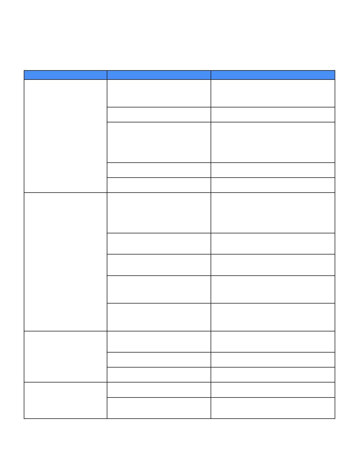
Symptom Possible Cause Remedy
Indicator light does not turn
on.
Unit is not connected to power source, or is
connected to improper power source.
Refer to label on side of chassis for voltage/frequency
requirements.
Connect unit to proper power source.
Safety Interlock Switch is not
engaged by chassis lid.
Remove lid. Bend “up interlock arm.
Fuse is blown. Visually inspect unit, and compare to wiring diagram.
Inspect Corona Discharge Cell for damage. Inspect
wire from High Voltage Transformer to Corona Dis-
charge Cell for disconnection or burn marks. Repair
any and all problems prior to placing unit in service, or
contact factory for service information.
Light is not receiving power. Connect light leads to power source per wiring dia-
gram.
Light has failed Refer to Spare/Replacement Parts for replacement
part information.
Unit keeps blowing fuses. Electrical short circuit. Visually inspect unit, and compare to wiring diagram.
Inspect Corona Discharge Cell for damage. Inspect
wire from High Voltage Transformer to Corona Dis-
charge Cell for disconnection or burn marks. Repair
any and all problems prior to placing unit in service, or
contact factory for service information.
Incorrect fuse value and type are being
used.
Compare fuse to label on side of unit. Replace with
appropriate size/type fuse. Refer to Spare/Replace-
ment Parts for replacement part information.
Unit is connected to improper power
source.
Refer to label on side of chassis for
voltage/frequency requirements.
Corona Discharge Cells were not installed. Install per Installation Manual. (Corona Discharge
Cells are shipped in a separate container to avoid
damage).
Corona outside of the Cell/Manifold has
established due to dirt or moisture within
chassis. Corona Discharge Cell is in need of
maintenance.
Perform Corona Discharge Cell maintenance and
Chassis maintenance in accordance with this manual.
Unit does not produce adequate
concentration of ozone.
Air ow rate is too high. Adjust air ow meter to lower setting, within range
specied in Air Flow Specication section of this
manual.
Unit is running too hot due to insucient
cooling air ow.
Refer to Air Flow Specication section of this manual.
Unit is connected to improper power
source.
Refer to label on side of chassis for voltage/frequency
requirements.
Unit does not produce adequate
concentration of ozone, even with
air ow rate set at levels that pre-
viously produced adequate ozone
concentration.
Corona Discharge Cells require mainte-
nance.
Refer to Corona Discharge Cell Maintenance Section
of this manual.
Air preparation device is not functioning at
prior level of performance.
Inspect/Maintain air preparation equipment in accor-
dance with manufacturer recommendations.
9.0 Troubleshooting Guide
Troubleshooting should be performed by a qualied electrician, in accordance with sound electrical safety
practices.
19
10.0 Standards
The transformer(s) in this unit are manufactured and tested (as applicable) to the following standards.
High voltage transformer, all models
(Part No. 40141) Underwriters Laboratories E176017
Step-down transformer, 230Vac models
(Part No. 40104) Underwriters Laboratories E86403 EN 60742
FIGURE 7 – OZ1 & OZ2BTU MOUNTING HOLE LOCATIONS
20
  • Page 1 1
  • Page 2 2
  • Page 3 3
  • Page 4 4
  • Page 5 5
  • Page 6 6
  • Page 7 7
  • Page 8 8
  • Page 9 9
  • Page 10 10
  • Page 11 11
  • Page 12 12
  • Page 13 13
  • Page 14 14
  • Page 15 15
  • Page 16 16
  • Page 17 17
  • Page 18 18
  • Page 19 19
  • Page 20 20
  • Page 21 21
  • Page 22 22
  • Page 23 23
  • Page 24 24
  • Page 25 25

Ozotech BTU Series User manual

Type
User manual

Ozotech BTU Series ozone generators utilize Cold Plasma Corona Discharge technology to produce high concentrations of ozone. They are designed for industrial, commercial, and residential applications, including odor control, air purification, water treatment, and food processing. Key features include:

  • Adjustable ozone output: The ozone output can be adjusted to meet specific needs.
  • Compact and lightweight: The BTU Series is easy to install and transport.
  • Durable construction: The units are made of stainless steel and aluminum for long-lasting performance.

Ask a question and I''ll find the answer in the document

Finding information in a document is now easier with AI