
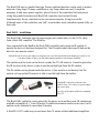
Beocompatible Operation via
Oneremote Interface Type 6102
Viasat HD
Pace TDS460NV/ Pace TDS850NV/ Pace DS830NV
Samsung DSB-H670N / Strong SRT
Beo4 and Beolink 1000 are remote control terminals from Bang & Olufsen. OneRemote supplies interface
modules that allow third party equipment to be operated via a Bang & Olufsen remote control system.
Made in Denmark by www.oneremote.dk
6102UKu1

Operating with Beo4 and Beo5
Beo4 and Beo5 do not have as many keys
as this receiver’s original remote control.
Thus certain Beo4/ Beo5 keys have got
alternative functionality.
To get to this Ohas to be pressed first,
i.e. Ofollowed by 1 corresponds to
info on the receiver’s own remote control.
The table to the right shows how special
Beo4/ Beo5 key operations translate to
operations of the original remote control.
To get the most of operating the receiver
with a Bang & Olufsen remote control, the
user has to be familiar with operations with
the original remote control as described in
the receiver’s user manual.
Power on the receiver
The receiver automatically powers up,
when the source is pressed on beo4, which
the bee2 controller is programmed for.
Usually this source might be s,
T, f or something else.
Fabric settings are f.
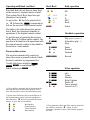
*1 It is possible to exchange the up/ down arrow the
functions with the blue and yellow buttons. This is
done with an option, refer to the installation pages.
*2 As the direct function of the coloured buttons on
the Beolink remote control has been reassigned to
other functions, Ohas to be pressed before these
buttons, to get to the colour function.
oE Red function
oQ Green Function
oW Yellow function
oR Blue function
Beo4/ Beo5 Daily operation
OO OK
W*2 *1 P+
R*2 *1 P-
Q*2 EPG
E*2 Back
m Setup
Harddrive operation
o Play press 1 second. *3
o0 Alternative play. *3
q Stop
o q Pause
oA Rewind
oS Forward
rr Record
Other operation
o1 info
o2 Ticket
o3 Planner
o4 Help/ Options
w Power off
o9 Power manual
oE Internal Text TV
*3 First generation Beo4 and other remote controls do
not send Play using the O button. Use the
alternative operation or have a B&O dealer upgrade
the Beo4.

Congratulations
With your bee2 controller from www.oneremote.dk you now
can fully operate your receiver using your Bang & Olufsen
remote control terminal, via a beeLINK system bus.
Beolink1000, Beo4 or Beo5 remote controls can be used. This
guide explains how.
This BeeLINK2 controller is ready for use, plug & play. See the
opposite page regarding daily operation.
Some operations can be altered, to improve interaction with
other controllers or to your convenience. Refer to the installation
section further on, if changes are needed.

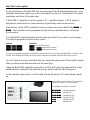
BeeLINK - How it works
The OneRemote beeLINK system is based on a 455 khz IR-receiver placed in the room.
Via a beeLINK amplifier it distributes control data to one or many different beeLINK
controllers or BeeLINK compatible devices, each designed for a specific purpose. One
controller is used for the TV, another controller for the DVD, a third for a beamer and so
on.
The BeeLINK system lets you control many devices, in a logic way. A single press on the
DTV button on the Beo4 might operate the TV, a receiver, an amplifier and a HDMI
switch at the same time. There are many solutions.
A beo4 remote control is not equipped with many keys, so we have designed a ‘layout’
that works logically, even when shifting control between different non B&O devices. To
get a common layout for many devices, we therefore needed to redefine a few of the beo4/
beo5 buttons to other functions:
• Coloured buttons.
To make room for more important functions, we have moved the coloured
buttons, to a lower layer. To send a ‘red’ button command O must be pressed
first. The same goes with the other 3 coloured buttons. This way we can assign
other functions to the coloured buttons, when pressed without a preceding go. In
a OneRemote environment the red button is used as Back, Backup or return. The
green button is used as EPG, Guide or similar. Finally the blue and yellow button
is used for programme stepping.
• Programme stepping, up/ down manoeuvring in menu’s.
Most set top boxes and TV’s has 4 arrow buttons for moving up, down, left and
right, in on screen menus. In addition to these buttons they also have separate
programme stepping buttons for zapping through programmes. B&O remote
controls do not include separate buttons for programme zapping.
We therefore have assigned the blue and the yellow buttons to function as
programme stepping buttons, in our basic setup. The four up, down, left and right
buttons have been assigned for manoeuvring in on screen menus, in our basic
setup.
It is possible to use the up and down arrow for programme stepping, refer to the
installation section.
• Go or Record shifted operation.
Some of the buttons has 2 or three functions. To get to these they have to be
preceded with O or r. Which buttons has secondary functions can be
seen in the operating table on page 2.

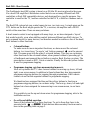
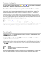
BeeLINK basics – the link amplifier.
To receive the IR data emitted from a Bang & Olufsen remote control, a B&O IR-receiver
is often used. If there is already one IR-receiver in the room, this can also be used to feed
the BeeLINK bus. Normally there is no need for two IR receivers in the same room.
A Bang & Olufsen IR-receiver connected to the
BeeLINK link amplifier with four BeeLINK
outputs.
Four BeeLINK controllers can be connected to
this link amplifier. One or more BeeLINK splitters
can be inserted to add outputs for more
controllers.
The shown 700mA power supply is capable of
driving the IR-receiver, the link amplifier and up
to 15 attached BeeLINK controllers.
This basic setup shows the core of a BeeLINK installation. Up to four BeeLINK
controllers or BeeLINK compatible devices can be connected to this linkamplifier.
BeeLINK basics – distribution of power and data.
The BeeLINK bus distributes the IR-data, received with the attached IR-receiver. It also
distributes 12 volt power from the attached power supply.
The cable used is ordinary CAT5 type cable with RJ45 plugs. The same type used for
computer networks. We chose this type as it is inexpensive and easy to crimp plugs on,
with inexpensive tools that all installers use as standard. Also it is well suited for data
transmission, and it provides us with extra leads for power supplying of the attached
BeeLINK controllers. Finally many modern house installations use the same connectors,
making installation even easier.
Note !
A BeeLINK bus must ONLY be connected to BeeLINK components.
If connected to LAN or other systems,
there is a great risk to damage these systems.

The BeeLINK bus is a parallel bus type. Passive splitters therefore can be used, to make a
network of any shape. If many controllers or very long cables are used, it might be
necessary to add more power supplies, placed closer to the controllers that lack power.
Using this parallel structure each BeeLINK controller receives the IR-data
simultaneously. Every controller has its own microcomputer, living its own life.
Although some of the controllers can ‘talk’ to each other, most controllers operate fully on
their own.
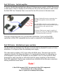
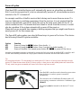
BeeLINK2 – installation
The BeeLINK2 controller gets its power supply and control data, via the CAT5 cable
from a BeeLINK amplifier. The BeeBus.
Once connected to the BeeBus the BeeLINK2 controller only needs an IR-emitter to
operate the device it has been designed for. The IR-emitter emits the same IR data as the
device’s own remote control.
Emitted IR data is in fact pure light at a frequency just out of the spectrum that the human eye is able to see.
It is short flashes of light, a bit like when sending morsing codes using a flashlight.
The emitter must be stuck on the device, nearby the TVs IR-receiver. It must be placed so
the IR receiver in the device is able to see the emitted light from the IR-emitter.
The IR-emitter can be placed inside the device, if you want to avoid having it on the
outside, as long as the IR-receiver is able to see the light from the emitter.
A BeeLINK2 controller connects to the
BeeBUS via a CAT5 cable, for power supply
and control data.
Typically an IR-emitter sends the commands
to the TV.
The BeeLINK2 controller can be placed by the device or in another room. IR emitters are
available in lengths of 1, 5 and 10 meters. In addition extension cords can be used. An IR-
emitter can be extended to more than 30 meters.
A BeeBUS CAT5 cable may exceed more than 75 meters without additional amplifiers.

BeeLINK2 connections.
The IR/ sense socket is output for the IR-emitter that sends IR to the device to be
operated. In some cases this socket is also used for sensing purposes. Sometimes the
BeeLINK2 controller needs to know if the device is powered up or not.
In some cases this socket is used for other serial communication like RS-232 instead of IR
control.
Prog switch is a push button that must be activated to initiate a programming sequence, as
described in the option programming chapters.
Do not use socket is for firmware updating of the controller. If used for anything else, the
controller may be damaged.
LED indicates different operating modes:
Red-green flash: No data has been received since power has been applied
Red flash: The controller is in option programming mode.
Red: The controller is active.
Green: The controller is inactive.
Short light off: When the controller sends data, the LED turns off 1 sec.
A BeeLINK2 controller connects to the BeeBUS via a RJ45
connector and CAT5 cable.
Warning:
If connected to a computer network,
this is likely to be damaged.
Connect only to a BeeLINK bus.

BeeLINK Active option.
As all controllers on the BeeLINK bus are receiving all the IR-data simultaneously, every
controller must know when to go active and when to go inactive. Sometimes two or more
controllers are active at the same time.
A BeeLINK 2 controller is used to operate a TV, a satellite receiver, a DVD-player, a
projector or similar devices. Each controller is specifically made for one device.
From factory a BeeLINK2 controller is set to go active on a source button like t or
d. The controller can be programmed to go active on another source, setting the
Active option.
Your BeeLINK2 controller needs to know when you want it to go active, in your setup.
You need to program it with an Active option.
Option Function
f 0r f turns on the receiver.
f 1r f + 1 turns on the receiver.
f 2r f + 2 turns on the receiver.
An option programming sequence is initiated by pressing the little red switch on the BeeLINK2 controller, until
its LED starts flashing. Hereafter the 3 digit option code must be entered with the B&O remote control.
Up to 10 receivers can be controlled this way, using the same source. This could be useful
when you have more than one device of the same type.
When the BeeLINK2 controller goes active, its LED will turn red to indicate this. When
another source is selected, the controller will go inactive and the LED turn green.
As the controller goes active, it will usually turn on the device, if it is not already turned
on.
Setup with 3 receivers and a PS3 playstation,
attached to both a TV and a projector.
One example of operation could be:
t1 Operate projector
t2 Operate TV
f1 Operate DVB-S
f2 Operate DVB-T
T Operate DVB-C
f Operate PS3

Programme Zapping option
In a BeeLINK environment the buttonsW and Rare being used for programme
stepping and to manoeuvre up and down in an on screen menu.
This is the basic OneRemote layout and compatible with other OneRemote controllers.
Some people prefer the programme zapping buttons on the up and down buttons. The
programme zapping option, make it possible to change the function of these buttons.
If the user would give it a fair chance, trying out the OneRemote layout, it is not likely
that he would make use of this option. The OneRemote layout adds much perspective to
many OSD menus on many devices, and makes sense once fully understood. But we are
up against habits, which we all wants to hang on to, so...
Option Function
090 W and Rare used for programme zapping.
091 D and Fare used for programme zapping. Factory setting.
An option programming sequence is initiated by pressing the little red switch on the BeeLINK2 controller, until
its LED starts flashing. Hereafter the 3 digit option code must be entered with the B&O remote control.
Menu button option
If the device is used in a setup that includes a Bang & Olufsen TV, sometimes the use of
the m button gives a conflict.
Some Bang & Olufsen TV act on the m and enters its own TV On Screen Menu
regardless of which source it is set to.
In these setups the Menu button must be disabled on the BeeLINK controllers. Instead of
using the Menu button to access the devices ‘Menu’, use the alternative menu operation
o5.
Option Function
080 Menu button blocked. Use alternative menu operation
081 Menu button enabled.
An option programming sequence is initiated by pressing the little red switch on the BeeLINK2 controller, until
its LED starts flashing. Hereafter the 3 digit option code must be entered with the B&O remote control.

Power off option
Most beeLINK controlled devices will automatically power on, when they are selected.
But it is not always practical if a device automatically powers off, when another source is
selected or the TV is turned off.
An example could be a Satellite receiver that is being used in more than one room. If a
user in a linkroom is watching programmes from the receiver, it is not practical that the
receiver automatically powers off, when the user in the main room turns off the TV or
selects another source. If a recorder has been timed to record from the receiver, it would
also be a problem if the system automatically powers off the receiver.
Many devices use so much time running a booting sequence that you might want them to
never power off, for this reason only.
The PowerOff option makes you select different ways to power off a device. This device
has following PowerOff options available:
Option Function
031 Power off using the w button. Press shortly. *1
032 Power off using the w button. Press 2 seconds for global standby. *1
033 Power off disabled. Use manual power button O9 to power off the device.
An option programming sequence is initiated by pressing the little red switch on the BeeLINK2 controller, until
its LED starts flashing. Hereafter the 3 digit option code must be entered with the B&O remote control.
Tip.
In a setup that includes a TV, this should be set with option 031. Some or all set top boxes should be set with
option 032. When the user turns off the TV after a session, a short press on the standby button will turn off the
TV only, and a long press on standby will turn of all of the set top boxes as well.
*1
Some BeeLINK controllers need to know the power status
from the device, in order to power it on and off
automatically.
This controller uses a OneRemote IR-emitter with a DC
type scartplug, to measure on the device. OneRemote type
34090051.
The scartplug must be inserted in the devices TV-scart
socket.

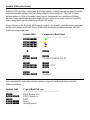
Beolink 1000 og Beo4 notes
Beolink 1000 and other early Bang & Olufsen remote controls are not equipped with the
coloured function buttons that have been added to Beo4 and Beo5. The lack of these
buttons makes it difficult to make a good layout, transparent for controlling different
devices. Some operations therefore might be less logical or in some cases not available,
when using these remote controls in a BeeLINK setup.
Some buttons on the Beolink 1000 remote controls, do actually send the same commands
as the new buttons on a Beo4/ Beo5. Other buttons simply has been renamed, but still
sends the same commands.
Beolink 1000 Compares to Beo4/ Beo5
------------------- --------------------------------
hZ Q
hX W
hC R
hV E
o P
v T
h v VTAPE2 /VMEM2 /DVD2
s f
h s d / CDV
h t a
y b
h y AMEM2
For compatibility with older remote controls, a typical OneRemote setup uses the
following buttons:
Beolink 1000 Typical BeeLINK use
---------------- -----------------------------------------
g Back, Backup e.t.c.
p g EPG, Guide e.t.c.
x EXIT.
p5 Menu.
p9 Manual power.

-
 1
1
-
 2
2
-
 3
3
-
 4
4
-
 5
5
-
 6
6
-
 7
7
-
 8
8
-
 9
9
-
 10
10
-
 11
11
-
 12
12


Ask a question and I''ll find the answer in the document
Finding information in a document is now easier with AI


Other documents
-
Sony 6124 User manual
-
 OneRemote 34016102 User manual
-
Bang & Olufsen BeoSystem 3 User manual
-
 One Remote OneRemote RMB4 User manual
-
-
-
-
Bang Olufsen Beocom 1600 Owner's manual
-
 One Remote OneRemote RMB4 User manual
-
 OneRemote RMB4 User manual


