Page is loading ...

Wemos D1 mini is an ESP8266 board that’s interesting thanks to its size, its low price ($4), micro USB
power, its shields, and a documentation that looks fairly good. The board can be programmed with
Arduino or Lua, and supports both serial and OTA programming. I’ve decided to give it a try and bought
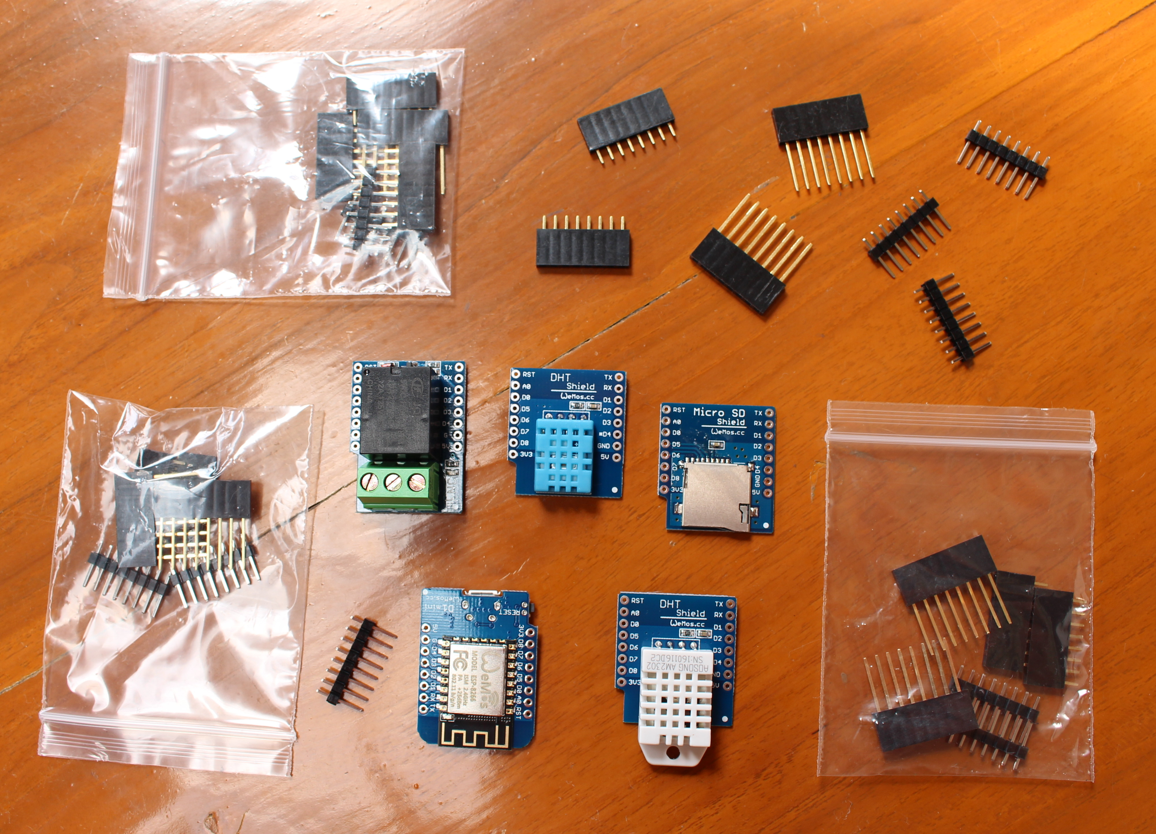
the board together with two temperature shields, a relay shield, and micro SD shield.
Click to Enlarge
I got all for $ 14.00 from Wemos Aliexpress shop, and it took about one month for delivery. I can also see
they’ve recently released a new OLED shield selling for about $5. All shields were shipped inside their
own anti-static bags.
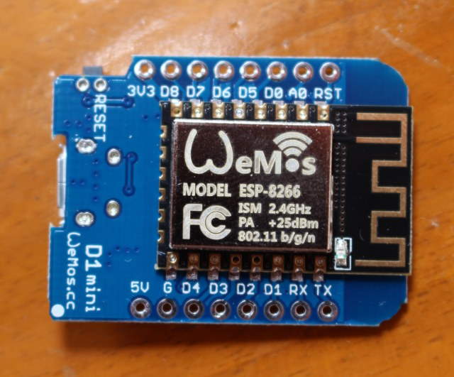
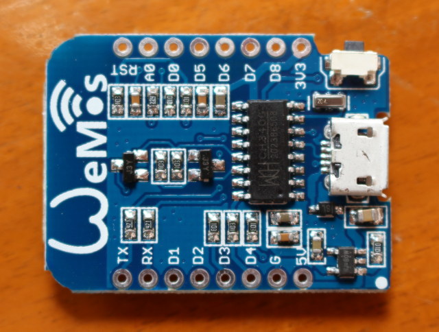
The pins are clearly marked on both side of the board and the shields. One side of the board features
ESP8266 module.


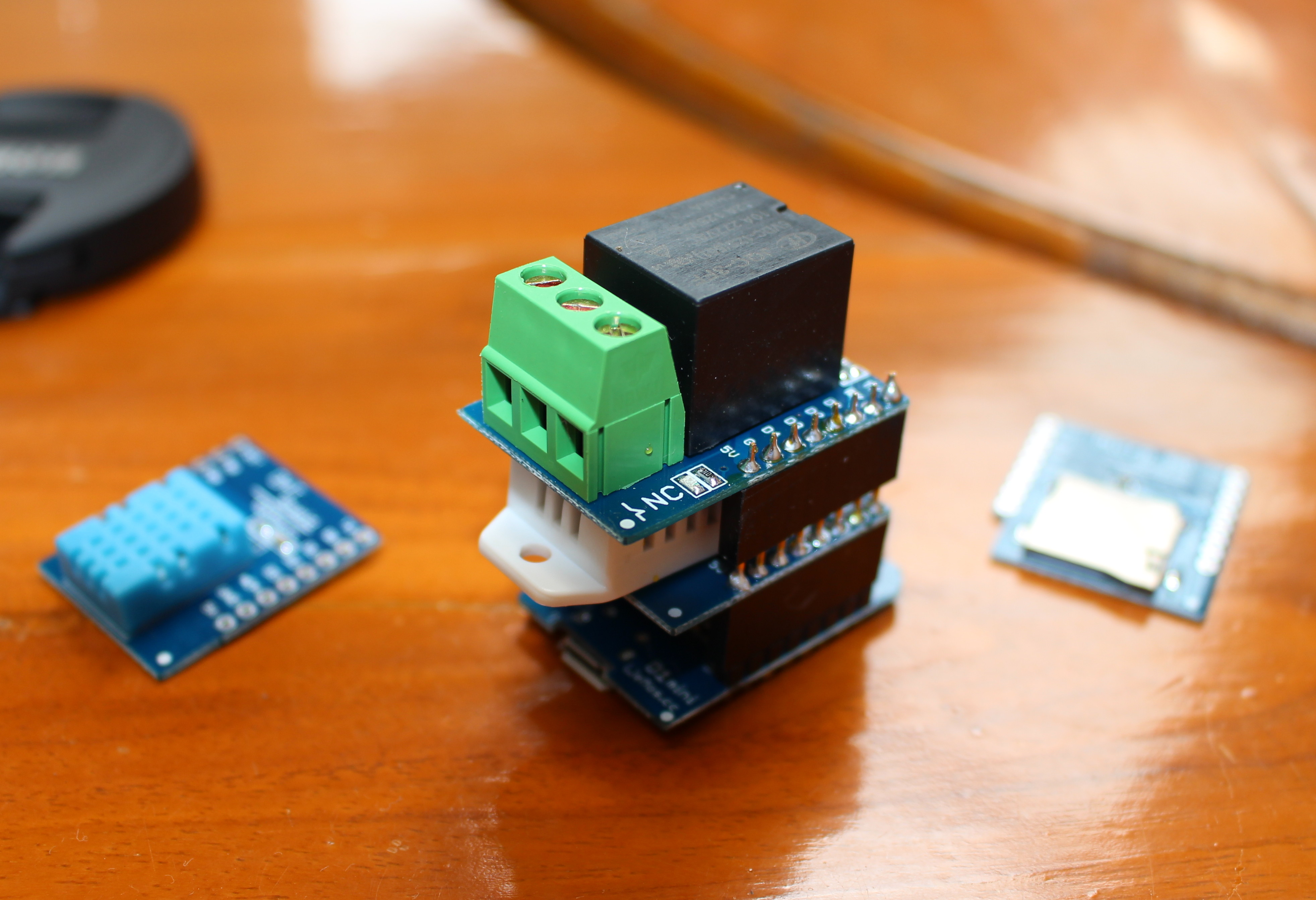
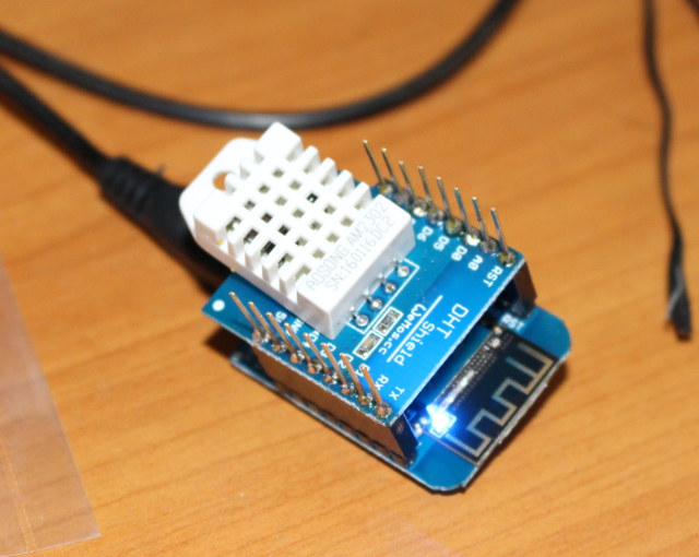
The provided headers make it easy to stack the board with several shields if you wish too. For example I
connect Wemos D1 mini to both the relay shield, and DHT Pro shield after soldering some of the headers.
The only potential pitfall would be to solder the header on the wrong side, so you just need to make sure
the pins (5V, RST,…) are properly aligned.

I’ve mostly followed the Getting Started in Arduino guide in Wemos.cc in this tutorial, and people who
prefer Lua/NodeMCU will want to check NodeMCU guide instead. There are various ways to configure the
Arduino IDE for WeMos D1 mini in the guide, but I’ve only used the recommended way: git.
The first step was to install and run Arduino 1.6.8. Since I’m using a computer running Ubuntu 14.04 64-
bit, I downloaded and installed Arduino 1.6.8 64-bit for Linux:
1
2
3
tar xvf arduino-1.6.8-linux64.tar.xz
cd arduino-1.6.8
./arduino
Now get the sketchbook folder by going to File->Preferences
Note this folder as this is where we’ll install the board support, tools and examples, and exit Arduino
before starting the installation:

1
2
3
4
5
6
cd
mkdir -p hardware
cd hardware
mkdir esp8266com
cd esp8266com
git clone https://github.com/esp8266/Arduino.git esp8266
download the binary tools:
1
2
cd esp8266/tools
python get.py
and finally install the examples:
1
2
cd
git clone https://github.com/wemos/D1_mini_Examples.git
Later on, you can update the board support files and the samples by running git pull in the two
directories where you ran git clone.
Now connect Wemos D1 mini to a USB port of your computer with a micro USB to USB cable. In Linux,
you should see a new device in the kernel log:
1
2
3
4
5
6
[ 8643.196931] usb 7-3: new full-speed USB device number 4 using ohci-pci
[ 8643.361709] usb 7-3: New USB device found, idVendor=1a86,
idProduct=7523
[ 8643.361717] usb 7-3: New USB device strings: Mfr=0, Product=2,
SerialNumber=0
[ 8643.361722] usb 7-3: Product: USB2.0-Serial
[ 8643.363826] ch341 7-3:1.0: ch341-uart converter detected
[ 8643.387870] usb 7-3: ch341-uart converter now attached to ttyUSB0
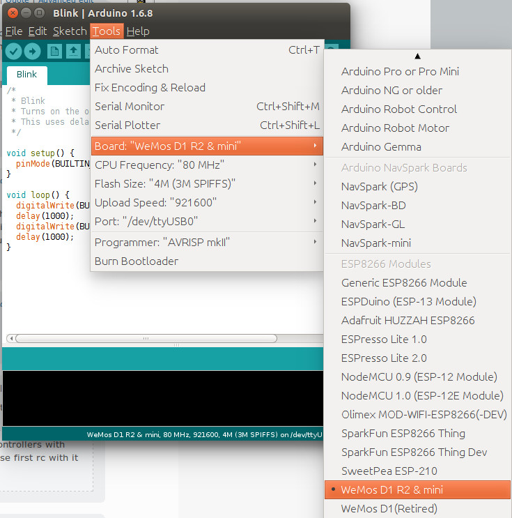
Let’s start Arduino 1.6.8 and select WeMos D1 R2 & mini in Tools->Board.


1
2
3
4
5
6
7
8
9
1
0
1
1
1
2
1
3
1
4
1
5
1
6
/*
* Blink
* Turns on the onboard LED on for one second, then off for one second,
repeatedly.
* This uses delay() to pause between LED toggles.
*/
void setup() {
pinMode(BUILTIN_LED, OUTPUT); // initialize onboard LED as output
}
void loop() {
digitalWrite(BUILTIN_LED, HIGH); // turn on LED with voltage HIGH
delay(1000); // wait one second
digitalWrite(BUILTIN_LED, LOW); // turn off LED with voltage LOW
delay(1000); // wait one second
}
Pressing the Upload button will build and upload to code to the board and once this is complete, the
build-in Blue LED (D4 / GPIO2) will blink every second. So my board is working.
As you can see I’ve already connected DHT Pro shield to the board, so let’s try the sample for the shield
to get the temperature and humidity in File->Sketchbooks->D1_mini_Examples->04. Shield-
>DHT_Pro_Shield->Simple:

/* DHT Pro Shield - Simple
*
* Example testing sketch for various DHT humidity/temperature sensors
* Written by ladyada, public domain
*
* Depends on Adafruit DHT Arduino library
* https://github.com/adafruit/DHT-sensor-library
*/
#include "DHT.h"
#define DHTPIN D4 // what pin we're connected to
// Uncomment whatever type you're using!
//#define DHTTYPE DHT11 // DHT 11
#define DHTTYPE DHT22 // DHT 22 (AM2302)
//#define DHTTYPE DHT21 // DHT 21 (AM2301)
// Connect pin 1 (on the left) of the sensor to +5V
// NOTE: If using a board with 3.3V logic like an Arduino Due connect pin 1
// to 3.3V instead of 5V!
// Connect pin 2 of the sensor to whatever your DHTPIN is
// Connect pin 4 (on the right) of the sensor to GROUND
// Connect a 10K resistor from pin 2 (data) to pin 1 (power) of the sensor
// Initialize DHT sensor.
// Note that older versions of this library took an optional third parameter to
// tweak the timings for faster processors. This parameter is no longer needed
// as the current DHT reading algorithm adjusts itself to work on faster procs.
DHT dht(DHTPIN, DHTTYPE);
void setup() {
Serial.begin(9600);

Serial.println("DHTxx test!");
dht.begin();
}
void loop() {
// Wait a few seconds between measurements.
delay(2000);
// Reading temperature or humidity takes about 250 milliseconds!
// Sensor readings may also be up to 2 seconds 'old' (its a very slow sensor)
float h = dht.readHumidity();
// Read temperature as Celsius (the default)
float t = dht.readTemperature();
// Read temperature as Fahrenheit (isFahrenheit = true)
float f = dht.readTemperature(true);
// Check if any reads failed and exit early (to try again).
if (isnan(h) || isnan(t) || isnan(f)) {
Serial.println("Failed to read from DHT sensor!");
return;
}
// Compute heat index in Fahrenheit (the default)
float hif = dht.computeHeatIndex(f, h);
// Compute heat index in Celsius (isFahreheit = false)
float hic = dht.computeHeatIndex(t, h, false);
Serial.print("Humidity: ");
Serial.print(h);
Serial.print(" %\t");
Serial.print("Temperature: ");
Serial.print(t);
Serial.print(" *C ");

Serial.print(f);
Serial.print(" *F\t");
Serial.print("Heat index: ");
Serial.print(hic);
Serial.print(" *C ");
Serial.print(hif);
Serial.println(" *F");
}
But this time I had an error during compilation, as DHT library is missing:
1
2
3
4
5
6
D1_mini_Examples/04.Shields/DHT_Pro_Shield/Simple/Simple.ino:10:17: fatal
error: DHT.h: No such file or directory
#include "DHT.h"
^
compilation terminated.
exit status 1
Error compiling for board WeMos D1 R2 & mini.
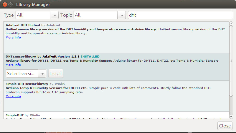
To fix that error, go to Sketch->Include Library->Manage Libraries, input dht to filter the library, and
install DHT sensor library by Adafruit.
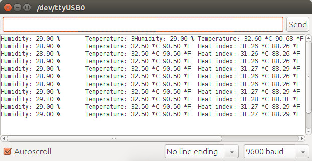
Now click on the Upload button again, the code will be compiled and uploaded to the board. Now open
the serial monitor with Ctrl+Shift M or Tools->Serial Monitor, and you should see the printed values for
the humidity in percent as well as the temperature & heat index in Celcius and Fahrenheit.

Th
e reported temperature matched the temperature reported by my IR thermometer (32.5 C). Pretty good.
If you’d like to get results displayed on a web page instead, you may want to modify DHT Shield-
>SimpleServer sample.
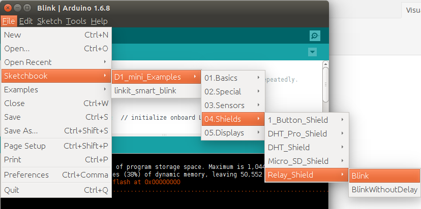
Now I’ll had the relay shield on top, and run another sample (File->Sketchbooks->D1_mini_Examples-
>04. Shield->Relay_Shield->Blink):
C

1
2
3
4
5
6
7
8
9
10
11
12
13
14
15
16
17
18
19
20
/*
* Relay Shield - Blink
* Turns on the relay for two seconds, then off for two seconds, repeatedly.
*
* Relay Shield transistor closes relay when D1 is HIGH
*/
const int relayPin = D1;
const long interval = 2000; // pause for two seconds
void setup() {
pinMode(relayPin, OUTPUT);
}
void loop() {
digitalWrite(relayPin, HIGH); // turn on relay with voltage HIGH
delay(interval); // pause
digitalWrite(relayPin, LOW); // turn off relay with voltage LOW
delay(interval); // pause
}
The relay blink sample will turn on and off the relay every two seconds. Since the DHT Pro shield uses D4
pin and the Relay shield uses D1 pin both can be used at the same time. I had no problem uploading the
sample to the board, and hearing the relay switch on and off every 2 second.
1/12


