Page is loading ...

Installation Instructions
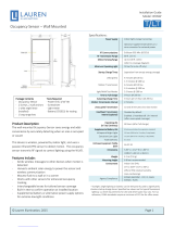
EOPC-100
Wireless Lighting Control System
Wireless Self-Powered PIR Ceiling Mount
Extended Range Occupancy Sensor
SPECIFICATIONS
Input Voltage: ............................. Self-Powered, Optional Battery
Operating Life at Full Charge: ............................................ 72 hrs
Time Delay: .............................................. 5-30 minute adjustable
ConnectiontoWirelessNetwork:.......... Transmits signal to Wall
SwitchReceiver(EOSW)viaRadioFrequency
Environment ................................................. For Indoor Use Only
Operating Temperature ....................32° to 131°F (0° to 55°C)
Storage Temperature ......................23° to 176°F (-5° to 80°C)
Relative Humidity ........................... 5 to 95% (non condensing)
Patent Pending
UNIT DESCRIPTION
WattStopper’s EOPC-100 Wireless Self-Powered Passive Infrared (PIR) Ceiling Mount Extended Range Occupancy Sensor
turns loads on and off based on occupancy and ambient light levels. It is self-powered using two built-in solar cells that
drawsonavailableambientlighttopoweritselfandcanoperateforupto72hours(3days)intotaldarkness.Itmustbe
fully charged prior to installation by exposing it to 20fc or 215lux for 4 hours to operate 24 hours. and charge for 12 hours to
operate72hours.Anoptionalbattery(CR2032,orequivalent)canbeusedforapplicationswithoutavailableambientlight,or
for instant operation at power up (not included with product).
Test Button
Pairing Button
Battery Tray
Sensitivity
Trimpot
EOPC100 BUTTON LOCATIONS
This device complies with part 15 of the FCC rules.
Operation is subject to the following two conditions:
1) this device may not cause harmful interference
and 2) this device must accept any interference
received, including interference that may cause
undesired operation.
SENSOR PLACEMENT 12’ MAX. HEIGHT
Sensor
28'
30'
COVERAGE PATTERN
The EOPC-100 provides a 360° coverage pattern. The
coverageshownrepresentsmaximumcoverageforwalking
motion at a mounting height of 8 feet.
Masking the PIR Lens: Opaqueadhesivetapeissuppliedsothat
sectionsofthePIRlenscanbemasked.Thisrestrictsthesensor’s
view and allows you to eliminate PIR coverage in unwanted areas
such as hallways outside of the desired coverage area. Since
maskingremovesbandsofcoverage,remembertotakethisinto
account when troubleshooting coverage problems.
Strong air
supply
6’
Sensor
Mount sensor at least 6’ away from air supply.
Avoid obstacles that block sensor’s line-of-sight.
Pendant
xture
44 ft
Extended Range
Lens (Standard)
EOPC-100
0'
30'
(9.1m)
20'
(6.1m)
10'
(3m)
5'
(1.5m)
0' 5'
(1.5m)
10'
(3m)
20'
(6.1m)
30'
(9.1m)
8' (2.4m)
12' (3.7m)
35'
(10.7m)
35'
(10.7m)
10' (3m)
TOP VIEW
44ft diameter @8ft
SIDE VIEW
Extended Range Lens (Standard)
Warning: Do Not Mount in a dark room (< 3 fc).
If necessary, please insert optional battery.
PLACEMENT GUIDELINES
OPERATION
The EOPC-100 depends on either the
EOSW-101/102 or EOSW-111/112
Wireless Receiver for operation. In order
to establish communication with one
another, all devices need to be Paired
together. Pairing refers to establishing
alinkbetweentwoormoredevicesfor
communication purposes. The EOPC can
only be Paired to other devices as it has
no direct connection to a load.
•The wireless receivers receive
signals from the Occupancy Sensor
(EOPC)viaradiofrequencyoncethey
are paired to the occupancy sensor.
•The EOPC-100 uses radio
frequenciestotransmitsignalstothe
wireless system.
Note: It is recommended that pairing
of devices be done prior to installing
ceiling sensor.

Visit our website for FAQs: www.wattstopper.com
TESTING THE OCCUPANCY SENSOR
“Test”modeallowsyoutoperformasensorwalktestto
define the coverage area, optimum sensitivity settings, and
product placement.
* WattStopper recommends you use a battery to perform
test mode otherwise the sensor may not have enough
power.ALithiumbatteryCR2032orequivalentare
recommended for use with the EOPC-100 sensor.
In “Test” mode, the sensor turns OFF all loads of receivers
within range after 5 seconds of no detection and begins a
10 minute test period.
Step 1: To Enter Test Mode
Tap the “Test” button on the
Occupancy Sensor
•The corresponding Time Delay
LED on the EOSW receiver(s)
blinkstoconfirmtimedelay
selection for reciever(s) paired
with the sensor that is in
“Test” mode. The LED at “15” over the Time Delay “T” is
to indicate the wall switches are in test mode with the
occupancy sensor EOPC-100.
•TheLEDstopsblinkingoncethesensorexitstestmode,
or by pressing and releasing the “Test” button on the
EOPC-100 at any time during the test mode.
•When the sensor doesn’t detect motion, all loads
controlled by the sensor will turn OFF after 5 seconds of
operation.
Step 2: Exit “Test” Mode
•The sensor will automatically exit test mode after 10
minutesandeachloadwilleithergobacktotheuser
definedsetvalueorback
to their selected time
delay default value (i.e.
Load 1 = 15 minutes, Load
2 = 30 minutes.)
Note: The 10 minute
windowismorethanlikely
torequirethatthesensor
be fully charged or use
the battery. To manually
exit “Test” mode to bypass the 10 minute window and reset
itbacktonormaloperation:
Tap the “Test” button on the Occupancy Sensor again
•The sensor exits test mode and the EOSW receiver LED
stopsblinking.
MAX
Test Button
TEST
MIN
PAIR
EOSW-102
“Load Status”
Blue LEDS
Time Delay
Button
Time
Delay
LEDs
MAX
Pairing Button
TEST
MIN
PAIR
EOPC100 BUTTON LOCATIONS
EOSW-102
“Load 1 Status”
Blue LED OFF
Pairing
Button
“Load 2 Status”
Blue LED On
PAIRING OF SENSOR TO RECEIVERS
*It is recommended that pairing of devices be done prior to
installing ceiling sensor.
Step 1: Enter Pairing Mode
Press and Hold “Pairing” Button “P” on
Receiver for 3 seconds then release:
•“Pairing”LEDblinks2times/
second to confirm pairing mode
For EOSW-101/EOSW-111
•Load 1 turns ON and is ready
to be paired
•Button 1 LED is Solid ON
For EOSW-102/EOSW-112
•Load1&2turnON and are
ready to be paired
•Button1&2LEDareSolidON
Step 2: Selecting a Specific Load to Pair
(EOSW-102/EOSW-112)
*By default, both loads turn On at the same time in Pairing
Mode. If both loads are to be controlled by Occupancy
Sensorthanskipthisstep.
Tap the “Pairing” Button “P” once while
in pairing mode:
•Load2turnsOFF and Load 1
remains ON
•Load 1 is now active and ready to be
paired to selected transmitters
•Load 1 LED is Solid ON
Tap the “Pairing” Button “P” once again
while in pairing mode:
•Load1turnsOFF and Load 2
turns ON
•Load 2 is now active and ready to be
paired to selected transmitters
•Load 2 LED is Solid ON
Tap the “Pairing” Button “P” a third time while in pairing
mode:
•Load1andLoad2turnON again, indicating both loads
are ready to be paired.
Step 3: Pair Occupancy Sensor to Receiver
* While the receiver is in pairing mode and the load you
want to pair the sensor with is ON:
Tap the “Pair”Button on the Occupancy Sensor
•Theselectedload(s)willflashOFF/ONforvisualpairing
confirmation
Step 4: Exit “Pairing” Mode on Receiver
Once a device is paired with the receiver the receiver will
automatically exit “pairing” mode.
•Thereceiverwillalsoexit“pairing”modeifnodeviceis
paired to it within 30 seconds.
•Pressingandholdingthe“Pairing”button“P”for 3
seconds also exits the pairing process.
Note: To pair additional devices to the same load, repeat
Step 1 to re-enter “Pairing” mode.
Step 5: Verify Occupancy Sensor is “Paired” with the
Receiver(s)
Tap the “Pairing” button “P” on the EOPC-100 while in
normal operating mode.
•The load(s) will turn OFF, and will turn ON immediately
(and remain On) if motion is detected.
TO “UNPAIR” ALL CONNECTED DEVICES
Press and hold the Pairing button “P” on the receiver
for about 10 seconds. The green LEDs will flash 3 times
indicating un-pairing has occurred.
“Load Status”
Blue LED
Pairing
Button
EOSW-101
EOSW-102
“Load Status”
Blue LED
Pairing
Button
EOSW-102
“Load 1 Status
”
Blue LED ON
Pairing
Button
IMPORTANT NOTE: THE MAXIMUM NUMBER OF OCCUPANCY SENSORS (EOPC-100)
AND WALL SWITCHES (EOSW-1XX) THAT CAN BE PAIRED TOGETHER IS TEN. WHEN
THE MAXIMUM NUMBER OF DEVICES HAVE REACHED THE LIMIT, THE GREEN PAIRING
“P” LED WILL FLASH RAPIDLY TO INDICATE THAT IT IS FULL.
IMPORTANT NOTE: YOU WILL HAVE
ONLY 30 SECONDS TO COMPLETE THE
PAIRING MODE OPERATION

Call 800.879.8585 for Technical Support
SENSOR MOUNTING
Mounting to junction box with mounting plate:
The EOPC-100 can be mounted to a pre-installed junction
box using the mounting plate that is provided. The
mountingplateworksonsingleordoublegangJ-boxes.
1. Attach mounting plate to junction box with the
provided screws.
2. Snap the sensor onto the mounting plate using the
threaded screw.
Mounting directly to junction box:
The EOPC-100 can also be mounted directly to a junction
box using the provided screws.
1. Usetwomachinescrews(includedwiththeJ-Box)to
attachthesensortothemountingtabsontheJ-Box.
2. AlignthesensorintheJ-Boxsothatthemounting
screwtabsontheJ-Boxmatchthekeyholesonthe
sensor’s rear housing.
4. Slide sensor onto the junction box.
WARNING:DoNotInstallToCoveraJunctionBoxHaving
Class 1, 3 or Power and Lighting Circuits.
Through ceiling tile:
The EOPC-100 can be mounted through the ceiling tile using
the mounting plate that is provided.
1. Attach mounting plate to ceiling tile as shown.
2. Drill hole in ceiling.
3. Line up threaded screw with hole in ceiling tile.
4. Snap the sensor onto the mounting plate through the
hole in ceiling tile using the threaded screw.
Mounting to solid wall:
The EOPC-100 can be mounted to a solid wall using the
paper template that is provided.
1. Usethepapertemplatetomarkthesurfaceofthewall
with appropriate hole spacings.
2. Drill holes in wall.
3. Use two machine screws (included) to mount the EOPC-
100tothesurface.Lineupscrewstomarkingson
surface.
4. Align the sensor so that the mounting screws on the
wallmatchthekeyholesonthesensor’srearhousing
and secure.
Junction box
Mounting plate
Screws
EOPC-100
Snap
Mounting plate
Ceiling tile
Line up threaded screw
with hole in ceiling tile
and screw in place
EOPC-100
Junction box
Screws
EOPC-100
Use Paper
Template to
mark surface
of wall.
Line up screws
to markings
on surface and
drill holes in wall.
EOPC-100 Sensor
Mounting to wood or non metal surfaces
The EOPC-100 can be mounted to any flat surface, or
placed directly on the surface using the reversable
mountingdiscprovided.Onesideofthediscisbackedwith
foam tape for mounting to non-metal surfaces; the reverse
side provides a super-magnet for
mounting to metal.
1. Use the pull tab to release
the mounting disc.
2. Snap the mounting disc into
insertonbackofsensor,tape
end face up.
3. Attach the sensor to the
desired location with the tape.
Mounting to metal surfaces
Use the super-magnet on the reversable mounting disc
(included) to mount to any metal surface such as fixtures or
metaldesks.
1. Use the pull tab to release the mounting disc.
2.Snapthemountingdiscontoinsertonbackof
sensor, magnet end face up.
3. Simply snap the sensor onto the surface.
Ceiling
Sensor Mount
Foam tape
(reversable
mounting
disc)
Adhere to
surface
Snap mounting disc
to mounting insert on
back of sensor, magnet
end face up. Snap magnet
to surface.
EOPC-100
Mounting
disc
Mounting
disc pull tab
Reversable mounting disc
One side is a super-
magnet for mounting
to metal, reverse side
acts as foam tape for
mounting to non-metal
surfaces
Pull tab to release mounting disc

11/2013
16585r1
Please
Recycle
2800 De La Cruz Blvd.
Santa Clara, CA 95050
Phone: 800.879.8585
www.wattstopper.com
TROUBLESHOOTING
Does the system work more reliably at close range
(without obstructions)?
Consider Factors Affecting the Environment:
In an indoor environment, the wireless controls have a
typical range of 30-150 feet. If there are obstructions
and/or noise interference the range will be less than the
typical range.
Obstructions:
The range can be reduced by metal objects (metal
decreases the effectiveness of RF transmission).
• Identifynearbymetal,concreteandotherobjects
possibly affecting signal strength
• Ifpossible,tryrelocatingthedevice(evenslightly)away
from obstructions to improve the system performance.
Does the system work better at certain times of the day?
• Lookforpiecesofequipmentthatmayaffectwireless
performance when they are ON
• Noiseinterferencecanbeeitherlinenoise(from
motors)orRadioFrequency(RF)
Sensor does not learn:
•Pleasechargefor10minutesinindoorlightorsunlight
before attempting to use, or insert optional battery
Sensor does not communicate to receiver:
• Checkpairingofthesensorafterinstalland
commissioning, press test button to test the range
(WITH A CHARGED SENSOR) if the load toggles, the
range is good. If the load does not toggle, pull the
sensor off the ceiling, verify charge by seeing the LED
on the SENSOR flash, then press test button to test with
the device close to the receiver, if still no load toggle,
the device is either not charged or has not been paired
properly (or may have even been unlearned) (see pairing
section above)
If device still doesn’t respond:
• Makesurethesensorispairedtothereceiverby
placing the receiver into pairing mode then tapping
once on the sensor’s pairing button.
• Iftheabovestepsdonotresolvetheproblemcall
technical support at: 800.879.8585.
WARRANTY INFORMATION
WattStopperwarrantiesitsproductstobefreeofdefectsinmaterialsandworkmanshipforaperiodof
five(5)years.TherearenoobligationsorliabilitiesonthepartofWattStopperforconsequentialdamages
arising out of or in connection with the use or performance of this product or other indirect damages with
respect to loss of property, revenue, or profit, or cost of removal, installation or reinstallation.
/