Operation Manual
I-Tech HD DriveCore Series Power Ampliers
page 4
I-Tech HD DriveCore Series Power Ampliers
Operation Manual
page 5
Table of Contents
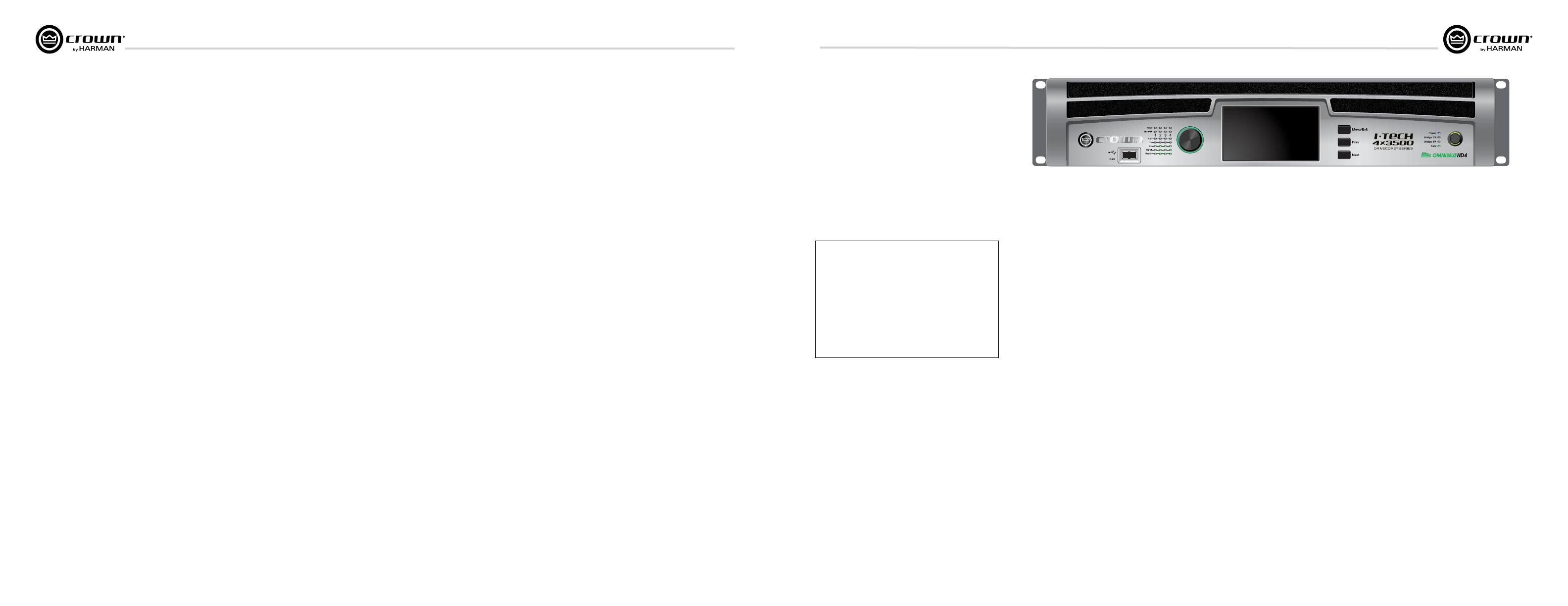
1 Welcome
The Crown
®
I-Tech
HD DriveCore Series offers
amazing power, light weight and ease of use for
touring sound applications. Unlike other
ampliers, it includes onboard high-denition
DSP, a 4.3” LCD screen, and a built-in network
connection.
Modern power ampliers are sophisticated
pieces of engineering capable of producing
extremely high power levels. They must be
treated with respect and correctly installed if
they are to provide the many years of reliable
service for which they were designed.
In addition, I-Tech Series ampliers include a
number of features which require some
expla nation before they can be used to their
maxi mum advantage.
Please take the time to study this manual so that
you can obtain the best possible service from
your amplier.
1.1 Features
• Global Power Supply with PFC (Power Fac tor
Correction) works anywhere in the world.
• High power density, up to 12,000 watts in a
2U chassis.
• Output voltage of 185Vpk provides clean
transient peaks.
• 6th-generation patented Class I (BCA
®
with
Drivecore Technology) cir cuitry couples power
efciently to the load and provides low AC
current draw.
• Onboard high-denition analog devices
Sharc
®
processor DSP with 24-bit, 192 kHz
SHARC A/D and D/A converters. Advanced IIR
lters and linear-phase FIR lters.
• Pushbutton presets simplify setup. Custom
presets for various loudspeakers can be
down loaded.
• AES3 digital audio input with V-Drive.
• EtherCon
®
Ethernet con nector for HiQnet™
control or CobraNet digital audio transport.
This “Single Plug” connection allows HiQnet
protocol and CobraNet digital audio, and
VDrive through the same CAT 5 cable.
• LCD Control Screen is used to adjust the
amplier’s attenuation and muting, congure
the amp, set up and view error monitoring, and
recall DSP presets to recongure the amp for
various applications.
• Comprehensive array of indicators provide
accurate diagnostics: Power, Data, along with
Ready, Signal, Clip, Thermal and Fault for each
channel.
• AC mains indicator in power switch glows
green when AC power is present.
• Front-panel USB connector accepts a USB
drive to transfer presets from the drive to the
amplier DSP, and vice versa. This feature also
allows you to update the amplier’s rmware.
• Light weight due to aluminum chassis,
spe cial internal construction, switching power
supply and patented class-I output stage with
DriveCore Technology.
• Thermal management controller and two
dis crete thermal zones with variable-speed fans,
forced-air cooling.
• Advanced protection circuitry guards against:
shorted outputs, DC, mismatched loads,
general overheating, under/over volt age,
high-frequency overloads and internal faults.
• Five-Year, No-Fault, Fully Transferable
Warranty completely protects your investment
and guarantees its specications.
1.2 How to Use This Manual
This manual provides you with the necessary
information to safely and correctly setup and
operate your amplier. It does not cover every
aspect of installation, setup or operation that
might occur under every condition. For
addi tional information, please consult the
online help in System Architect software,
Crown’s Amplifier Application Guide, I-Tech
Application Guide (available online at www.
crownaudio.com), Crown Technical Sup port,
your system installer or retailer.
We strongly recommend you read all
instruc tions, warnings and cautions contained
in this manual. Also, for your protection, please
send in your warranty registration card today.
And save your bill of sale — it’s your ofcial
proof of purchase.
I-T4x3500HD
2-ohm
2.7-ohm
4-ohm
8-ohm
4-ohm Bridge
8-ohm Bridge
70Vrms Direct
100Vrms Direct
20 Hz - 20 kHz
Minimum power in watts with 0.35% THD, all channels driven.
1,900W
2,100W
2,400W
1 kHz 20ms Burst
7,000W
6,000W
1,900W
3,500W
2,200W 3,800W
4,000W
4,200W
4,800W
2,100W
2,300W
Important Safety Instructions ............................................................ 2
Declaration of Conformity ..................................................................3
Table of Contents ..............................................................................4
1 Welcome ........................................................5
1.1 Features ................................................................................. 5
1.2 How to Use This Manual .........................................................5
2 Setup .............................................................6
2.1 Unpack and Install Your Amplier .......................................... 6
2.2 Connecting to AC Mains ........................................................7
2.3 Wire Inputs and Outputs .........................................................7
3 HARMAN GreenEdge - Going ‘Green’ ........................11
3.1 Going ‘Green’ .......................................................................... 11
3.2 The Sound of Efciency ..........................................................11
3.3 Green Savings ........................................................................11
4 Integraded DriveCore
TM
Technology ..........................12
5 Powered by Crown ..............................................13
6 Operation ........................................................14
6.1 Protecting Your Speakers .......................................................14
6.2 Startup Procedure .................................................................. 14
6.3 Precautions ............................................................................14
6.4 Front Panel Controls and Indicators ........................................ 15
6.5 Back Panel Controls, Indicators and Connectors ..................... 16
7 Advanced Operation ............................................17
7.1 Introduction ............................................................................ 17
7.2 Operation Example ..................................................................18
7.3 Presets ................................................................................... 27
7.4 List of Pop-Up and Descriptions ............................................. 28
7.5 Digital Audio Options (AES3 and VDrive) ................................ 29
7.6 Networking the Amplier ......................................................... 29
7.7 Software- Controllable Onboard DSI ....................................... 29
8 Troubleshooting ................................................44
9 Specications ...................................................46
10 AC Power Draw and Thermal Dissipation ..................50
11 Advanced Features ............................................ 51
11.1 Protection Systems ............................................................... 51
11.2 Global Switching Power Supply with PFC ............................. 51
11.3 6th Generation Class I Circuitry ............................................ 51
11.4 Color-Coded Rear Overlay .................................................... 51
12 Appendix A: Network and CobraNet Basics ................52
12.1 HiQnet Networks ................................................................... 52
12.2 A Closer Look at CobraNet .................................................... 52
13 LevelMAX
TM
Limiter Suite ....................................56
14 LevelMAX Limiters ............................................ 57
14.1 LevelMAX Peak Limiter ......................................................... 57
14.2 Peak Limiter Threshold (Vpk) ................................................ 57
14.3 Peak Limiter Attach (sec)....................................................... 57
14.4 Peak Limiter Release (sec) .................................................... 57
14.5 Peak Limiter Look Ahead....................................................... 57
14.6 Level MAX RMS Limiter ........................................................ 57
14.7 RMS Threshold (VRMS) ....................................................... 57
14.8 LevelMAX Tranducer Thermal Limiters ................................. 57
14.9 Thermal Voltage (VRMS) ...................................................... 57
14.10 Thermal Response Time (s)................................................. 57
15 Appendix B: Table of Parameters Modied by Each Mode
with LevelMAX ....................................................58
16 Application of FIR Filters to Loudspeakers Crossovers ..60
16.1 FIR Overview ......................................................................... 60
16.2 What are IIR Filters and FIR Filters? ....................................... 60
16.3 Pros and Cons of IIR and FIR Filters ...................................... 60
16.4 Desirable Attributes of FIR Filters .......................................... 60
16.5 High Rolloff and Steep Slopes ............................................... 61
16.6 Stop-band Attenuation .......................................................... 61
16.7 FIR Polar Lobing Eror............................................................ 61
16.8 Crown’s Implementation of FIR Filters ................................... 61
16.9 FFT Convolution ................................................................... 61
16.10 Filter Design ....................................................................... 61
16.11 Low Latency 96 kHz Studio Quality Filters ........................... 62
16.12 Measurements of Two-way Loudspeaker System ................ 62
16.13 FIR Measurements .............................................................. 64
16.14 Conclusions ....................................................................... 65
17 Service .......................................................... 66
17.1 International and Canada Service .......................................... 66
17.2 US Service ............................................................................ 66
18 Warranty ........................................................ 67