Robertshaw 6500 M Series Infinite Switch Kit User manual

Type
User manual

Robertshaw 6500 M Series Infinite Switch Kit is a voltage sensing, parallel circuit switch designed to replace VSI (INF) switches in Canada. With a heavy-duty dial shaft that can be broken off to the required length, this compact and lightweight control is suitable for various OEM applications. It features clockwise or counterclockwise shaft rotation, a controllable range of output power with detents, and easy installation with screw or palnut mounting options.

Robertshaw 6500 M Series Infinite Switch Kit is a voltage sensing, parallel circuit switch designed to replace VSI (INF) switches in Canada. With a heavy-duty dial shaft that can be broken off to the required length, this compact and lightweight control is suitable for various OEM applications. It features clockwise or counterclockwise shaft rotation, a controllable range of output power with detents, and easy installation with screw or palnut mounting options.

INSTALLATION DATA
6500 M SERIES INFINITE SWITCH KIT
The Robertshaw
®
6500 M Series is a voltage sensing (parallel circuit)
innite switch designed to replace the current VSI (INF) switch in Canada.
This patented control is the smallest physical dimension possible to meet
common applicaon specicaons.
The 6500 M Series has a heavy-duty dial sha that can be broken o to the
required length to adapt to numerous OEM applicaons.
Specicaons:
UL Approved #E112536
15 Amps @ 120/240 Volt 50/60 Hz for 200°F (93°C) ambient
13 Amp rang for all temperatures up to the maximum ambient
temperature of 257°F (125°C)
Key Features:
Clockwise or Counterclockwise sha rotaon from OFF
Controllable range of output power with LO and HI detents
Compact and lightweight design
PANEL
ì VENTSUPî
FLATHEAD
SCREWS
Figure 3
Figure 1
INSTALLATION INSTRUCTIONS
CAUTION: This device should be installed by a qualied service technician
with due regard for safety, as improper installaon could result in a
hazardous condion.
1. Unplug range or disconnect power.
2. Remove dial from switch.
3. Gain access to the inoperave switch. Refer to the original user manual
for the appliance for proper disassembly.
4. Label all wires with tags or make an exact drawing of wiring
conguraon before removing any wires.
5. Remove original switch.
6. Determine mounng type for the new switch: Screw Mount or Palnut.
Note: The 6500 M must be mounted with the sloed vents at the top.
Screw mount (Figure 1) is the most common. Aach the new switch to
the rear panel with the original screws or using the two athead screws
supplied in the kit.
Palnut mount (Figure 2) requires adding the bushing and the bracket
before inserng the sha through the rear panel. Use the two smaller
Phillips head screws to aach the bracket vercally or horizontally to
the new switch. Secure the switch (nger snug) to the rear panel with
the palnut.
7. Temporarily mount the switch and place the original dial on the new
switch sha. Make sure the sha goes in all the way.
8. Measure the distance from the back the of dial to the front of the panel
and subtract an 1/8”. This measurement is needed in the next step.
9. Remove the switch. Use the measurement from the previous step and
measuring from the end of the sha, mark the sha at the nearest
break-o point (or at the next break-o groove toward the end of the
sha to avoid breaking o too short).
PANEL
BUSHING
PALNUT
PHILLIPS
HEADSCREWS
BRACKET
(MOUNTVERTICALLY
ORHORIZONTALLY)
VENTSUP
Figure 2
10. To break o the sha, use two (2) pairs of pliers – one on each side
of the marked groove (Figure 3). Hold pliers rmly and break the
sha. DO NOT HOLD SWITCH BODY.
11. See Figure 4 and 5 for the locaon where the spring clip is required
and snap on as shown in the illustraon.
Figure 4
Figure 5
Figure 3
Figure 2
Figure 1
WIRING ROBERTSHAW INF TO ROBERTSHAW 6500 M SERIES
Connect wires from old switch to new switch as follows:
INF Switch 6500 M (MPA) Switch
Terminal # Terminal #
L1 connect to L1
L2 connect to L2
P connect to P
H1 connect to H1
H2 connect to HC
WIRING EGO TO ROBERTSHAW
Old (EGO) Switch 6500 M (MPA) Switch
Terminal # Terminal #
P1 connect to L2
P2 connect to L1
Pilot Pilot connect to P
4 4 connect to H1
2 2 connect to HC
(L2)
(P)
(L1)
(H1)
(HC)
(L2)
(P)
(L1)
(H1)
(HC)
0.75
0.75
1.10
MAX DISTANCE
0.614
1.50
0.8860.886
1.77
(4X) 8-32 MOUNTING NUTS
WIRING SCHEMATIC
WARNING: The rear housing has a ¼”
diameter hole which is an access point to
be used ONLY by qualied personnel for
insuring proper assembly and calibraon
of the switch. Any tampering with
internal components or altering factory
sengs of this switch will possibly
damage other electrical components on
the appliance and will immediately VOID
the WARRANTY of the switch.
MOUNTING DIMENSIONS
ORDERING INFORMATION
Customer Service Telephone 1.800.304.6563
Customer Service Facsimile 1.800.426.0804
Robertshaw® and Uni-Line® are trademarks of Robertshaw, its
subsidiaries and/or affiliated companies. All other brands mentioned
may be the trademarks of their respective owners.
For Technical Service
Telephone 1.800.445.8299
www.robertshaw.com
©2017 Robertshaw
09/17 –352-00268-001
UNI-LINE
®
PART NUMBER OEM PART NUMBER UNILINE PART
®
NUMBER OEM PART NUMBER VOLTAGE NOTES
6500-208M MPA-V652-ICM 6500-208 INF-240-1134 240 STEM FLAT DOWN
6500-209M MPA-V653-ICM 6500-209 INF-240-1135 240 STEM FLAT RIGHT
6500-25M MPA-V601-1-ICM 6500-25M INF-120-1133 120 STEM FLAT DOWN
6500 M SERIES
REPLACES
DONNÉES D’INSTALLATION
ENSEMBLE COMMUTATEUR
ÀRÉGLAGE INFINI SÉRIE 6500 M
Le commutateur Robertshaw
®
Série 6500 M est un commutateur à réglage
inni et détecon de tension (circuit parallèle) desné à remplacer le
commutateur VSI (INF) au Canada. Cee commande brevetée présente
la plus pete dimension physique possible conforme aux spécicaons
d’applicaon courantes.
La série 6500 M a une ge de cadran ultra-robuste qui peut être cassée
à la longueur requise pour l’adapter aux nombreuses applicaons OEM.
Spécicaons:
Homologué UL #E112536
15 A à 120/240 V, 50/60 Hz pour une température ambiante de 200 °F (93 °C)
Intensité nominale de 13 A pour toutes les températures jusqu’à
la température ambiante maximum de 257 °F (125 °C)
Caractérisques clés:
Rotaon de ge dans le sens horaire ou an-horaire à parr de
la posion ARRÊT
Plage de puissance de sore réglable avec détentes MIN. et MAX.
Concept compact et léger
PANNEAU
FENTES VERS LE HAUT
VIS À TÊTE
PLATE
Figure 1
INSTRUCTIONS D’INSTALLATION
ATTENTION: Ce disposif doit être installé par un agent technique qualié
qui respecte les consignes de sécurité, car une installaon impropre peut
se solder par des condions dangereuses.
1. Débrancher la cuisinière ou couper le courant.
2. Déposer le cadran du commutateur.
3. Accéder au commutateur inopérant. Se référer aux instrucons
de démontage dans le manuel de l’ulisateur d’origine de l’appareil.
4. Équeter tous les ls ou dessiner un croquis exact de la conguraon
des ls avant de les débrancher.
5. Déposer le commutateur d’origine.
6. Déterminer le type de montage pour le nouveau commutateur:
montage par vis ou par écrou autoleteur.
Remarque: Le 6500 M doit être monté avec les fentes d’aéraon sur
le dessus. Un montage par vis (Figure 1) est le plus courant. Aacher
le nouveau commutateur au panneau arrière avec les vis d’origine ou
à l’aide des deux vis à tête plate fournies dans l’ensemble.
Un montage par écrou autoleteur (Figure 2) exige l’ajout de la douille
et du support avant d’insérer la ge dans le panneau arrière. Uliser
les deux petes vis cruciformes pour aacher le support vercalement
ou horizontalement au nouveau commutateur. Serrer à la main
le commutateur sur le panneau arrière avec l’écrou autoleteur.
7. Monter temporairement le commutateur et placer le cadran
d’origine sur la nouvelle ge du commutateur. S’assurer que
la ge est complètement enfoncée.
8. Mesurer la distance de l’arrière du cadran à l’avant du panneau
et soustraire 1/8 po (3mm). Cee mesure est indispensable
pour l’étape suivante.
PANNEAU
DOUILLE
VIS CRUCIFORMES
SUPPORT
(MONTAGE VERTICAL
OU HORIZONTAL)
FENTES VERS LE HAUT
ÉCROU AUTOFILETEUR
Figure 2
9.  Déposer le commutateur.
Uliser la mesure de l’étape
précédente et, en mesurant
à parr de l’extrémité de la
ge, marquer la ge au point
de rupture le plus proche (ou
à la rainure de rupture suivante
vers l’extrémité de la ge pour
éviter de casser trop court).
10. Pour casser la ge, uliser deux
(2) pinces – une de chaque
côté de la rainure marquée (Figure 3). Tenir fermement les pinces et
casser la ge. NE PAS TENIR LE CORPS DU COMMUTATEUR.
11. Pour l’emplacement requis pour l’agrafe à ressort, se reporter
aux gures 4 et 5 et l’enclencher en posion, comme indiqué
sur l’illustraon.
RAINURE
MÉPLAT
À DROITE
REMPLACE LES ANCIENS TYPES DE TIGE, COMME ILLUSTRÉ
MÉPLAT
À GAUCHE
MÉPLAT
0,170 po (0,431 cm)
0,190 po
(0,482 cm)
0,190 po
(0,482 cm)
0,200 po
(0,508 cm)
MÉPLAT
À GAUCHE
INSTALLER
L'AGRAFE
CÔTÉ MÉPLAT
INSTALLER
L'AGRAFE
CÔTÉ RAINURE
INSTALLER
DEUX AGRAFES
CÔTÉ MÉPLAT
(DOS À DOS)
RAINURE
MÉPLAT VERS
LE BAS
INSTALLER
L'AGRAFE
CÔTÉ MÉPLAT
INSTALLER
L'AGRAFE
CÔTÉ RAINURE
INSTALLER
DEUX AGRAFES
CÔTÉ MÉPLAT
(DOS À DOS)
MÉPLAT VERS
LE HAUT
MÉPLAT VERS
LE HAUT
REMPLACE LES ANCIENS TYPES DE TIGE, COMME ILLUSTRÉ
MÉPLAT
0,170 po
(0,431 cm)
0,190 po
(0,482 cm)
0,190 po
(0,482 cm)
0,200 po
(0,508 cm)
Figure 4
Figure 5
Figure 3
Figure 3
Figure 2
Figure 1
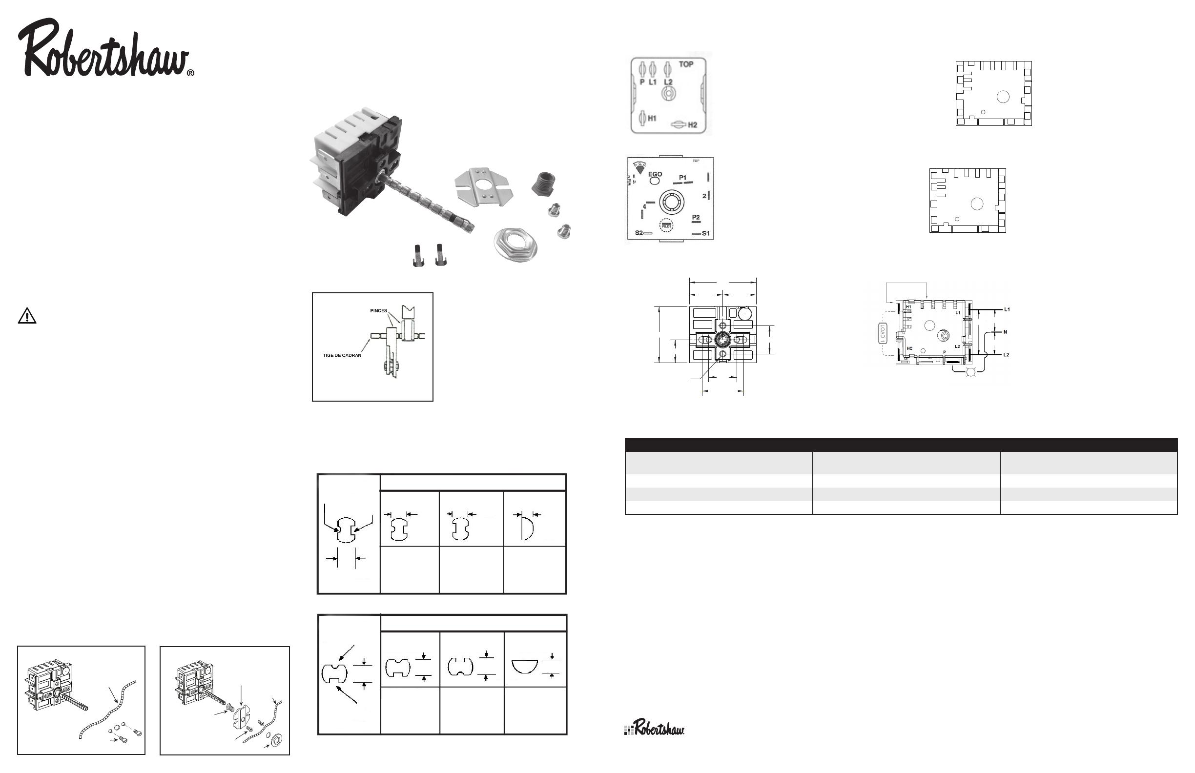
CÂBLAGE D’UN COMMUTATEUR INF ROBERTSHAW SUR UN COMMUTATEUR ROBERTSHAW SÉRIE 6500 M
Brancher comme suit les ls de l’ancien commutateur sur le nouveau:
N
o
de borne N
o
de borne du commutateur
du commutateur INF 6500 M (MPA)
L1 brancher sur L1
L2 brancher sur L2
P brancher sur P
H1 brancher sur H1
H2 brancher sur HC
CÂBLAGE D’EGO SUR ROBERTSHAW
N
o
de borne de l’ancien N
o
de borne du commutateur
commutateur (EGO) 6500 M (MPA)
P1 brancher sur L2
P2 brancher sur L1
Veilleuse brancher sur P
4 4 brancher sur H1
2 2 brancher sur HC
(L2)
(P)
(L1)
(H1)
(HC)
(L2)
(P)
(L1)
(H1)
(HC)
0.75
0.75
1.10
DISTANCE MAX.
0.614
1.50
0.8860.886
1.77
4 ÉCROUS DE MONTAGE 8-32
SCHÉMA DE CÂBLAGE
AVERTISSEMENT: Le boîer arrière a un
trou de ¼ po (6 mm) de diamètre qui est
un point d’accès RÉSERVÉ à un personnel
qualié pour garanr l’assemblage et
l’étalonnage corrects du commutateur.
Toute altéraon des composants internes
ou modicaon des réglages en usine de
ce commutateur risque d’endommager
d’autres composants électriques sur
l’appareil et ANNULERA immédiatement
la GARANTIE du commutateur.
DIMENSIONS DE MONTAGE
COMMANDES
Service à la clientèle Téléphone 1.800.304.6563
Service à la clientèle Télécopieur 1.800.426.0804
Robertshaw® et Uni-Line® sont des marques de commerce
de Robertshaw et/ou de ses filiales. Toutes les autres marques
mentionnées peuvent être les marques de commerce de leur
propriétaire respectif.
Service technique
Téléphone 1.800.445.8299
www.robertshaw.com
©2017 Robertshaw
09/17 –352-00268-001
NUMÉRO DE RÉFÉRENCE
UNI-LINE
®
NUMÉRO
DE RÉFÉRENCE OEM
NUMÉRO
DE RÉFÉRENCE UNILINE
®
NUMÉRO
DE RÉFÉRENCE OEM
TENSION NOTES
6500-208M MPA-V652-ICM 6500-208 INF-240-1134 240 MÉPLAT DE TIGE VERS LE BAS
6500-209M MPA-V653-ICM 6500-209 INF-240-1135 240 MÉPLAT DE TIGE À DROITE
6500-25M MPA-V601-1-ICM 6500-25M INF-120-1133 120 MÉPLAT DE TIGE VERS LE BAS
SÉRIE 6500 M
REMPLACE
POUR LES VEILLEUSES 240 V;
-- CONNECTER LES CONDUCTEURS
DE VEILLEUSE SUR « P » ET « L2 »
Veilleuse 120 V
120 V
120 V
240 V
À MONTER DE L’UN OU L’AUTRE
CÔTÉ DE CES DEUX (2) CÔTÉS
À FENTES DE VENTILATION
VERS LE HAUT
  • Page 1 1
  • Page 2 2

Robertshaw 6500 M Series Infinite Switch Kit User manual

Type
User manual

Robertshaw 6500 M Series Infinite Switch Kit is a voltage sensing, parallel circuit switch designed to replace VSI (INF) switches in Canada. With a heavy-duty dial shaft that can be broken off to the required length, this compact and lightweight control is suitable for various OEM applications. It features clockwise or counterclockwise shaft rotation, a controllable range of output power with detents, and easy installation with screw or palnut mounting options.

Ask a question and I''ll find the answer in the document

Finding information in a document is now easier with AI