Page is loading ...

General Required Tools
* Pencil or water soluble felt pen
* Hacksaw with 24 tooth blade
* Metal file (smooth sharp edges)
* Tape measure
* Drill, electric or battery
* #2 Phillips Screw driver
* 3/16" drill bit carbide for tile
* 5/16” drill bit carbide for tile
* Caulking gun
* Clear 100% Silicone
(recommended)
* 4 ft. Level
* Rubber mallet
* Razor knife
* Blue painters tape
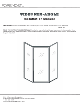
ECSE180
Shower Slider & 180° Panel
ECTE180
Tub Slider & 180° Panel
Pick a unit below that best represents your configuration.
IMPORTANT: Warnings and General Shower Door Information
Page 2
Thank you for purchasing this outstanding product!
This booklet will help you install your units safely and successfully.
SAFETY
WARNINGS:
GLASS FRAGILESHARPCAUTIONHEAVY
Scan this Barcode for Parts Bag BP.5004.NTL
Installation Instructions
Models: ECTE180 / ECSE180
3/8" Frameless Slider & 180° Panel
MM.5004_Rev. 05.8.2018
P/N MM.5004
rev061818

CAUTION - READ THOROUGHLY BEFORE INSTALLATION
Follow instructions: Instructions must be read and followed carefully to reduce the risk of
serious injury during and after installation. Any deviation from these instructions can create
safety hazards.
Tempered Glass: Agalite enclosures glass panels are safety tempered to conform to general
building codes. The intent of tempering is to reduce the risk of injury. Be careful handling
tempered glass. Pay special attention to protect all edges of the glass from contact with hard
surfaces.
General Notes:
- Exposed ends of aluminum and other hard components can be rough, sharp or jagged due to
the processes of cutting, drilling, notching, etc. Sharp ends must be deburred, smoothed or rounded
by the installer before installation. Failure to do so could result in serious injury to installer and user of
the enclosure.
- Sliding and swinging glass doors hitting any unprotected bathroom obstruction or metal or
glass component of the shower door itself, may indicate improper installation and could lead to glass
breakage or serious injury. The installer must correct the deficiencies before allowing the door to be
used.
- Towel Bars, handles and other accessories are in no way considered to be grab bars or other
bracing or fall prevention mechanisms. The intent of these accessories is to facilitate proper
operations and esthetics of the unit.
Drilling holes in horizontal surfaces: Drilling holes to anchor horizontal sills and curbs to
thresholds and tub decks is discouraged. Using masking tape or double-sided tapes to secure non-
load bearing components during installation (permanently secured later with silicone/caulking) is one
technique to help minimize potential of water leaking underneath flooring. These instructions do not
recommend drilling holes on horizontal surfaces for this reason.
Shower Doors are Not Watertight: Depending on the type of shower door selected, a properly
designed and installed shower enclosures will protect areas outside of the enclosure from water
damage under normal shower conditions to varying degrees. Excessive water pressure or directing
the shower head or hand held sprays directly at doors or joints is not a normal shower conditions and
can result a leak. The amount of water that can escape your shower varies by the type of shower as
well. Heavy glass units with no or limited vinyl seals will allow water to escape under normal
conditions. In general, the more metal and seals in the unit, the more water protection will be
achieved.
Metal Colors:
- Anodized Aluminum: The color of anodized Silver, Brushed Nickel, Satin Silver, Dark Bronze,
and Gold anodized aluminum will vary between adjacent components because of variblities within
polishing, anodizing process and alloy composition. We make every effort to limit the variation; but, it
is allowable and must be accepted.
- Electro Plated Brass and Stainless Steel: The color of Silver, Brushed Nickel, Satin Silver, Oil
Rubbed Bronze, Dark Bronze, and Gold electro plated components will also vary. This is allowable.
Most of these finishes are also “living finishes”, meaning, they may change, wear, weather, show
patina, oxidize, etc. over the life of the product. This is allowable.
- Powder Coat: This is a painting process and therefore can achieve the best color matching.
Power coat paint, however, is less durable at joints of moving components and at edges that have
been cut after the powder coat has cured. Some flaking or chipping in these areas are allowable.
- All Metal: Any metal component (and glass components as well) will have limited scratches and
pits. We make every effort to limit them; but, they are allowable and must be accepted.
Cleaning and Care: refer to your owners manual for cleaning and care instructions.
SAFETY
WARNINGS:
Shower Door Facts
GLASS FRAGILESHARPCAUTIONHEAVY
Page 2

Installation Instructions
Models: ECTE180 / ECSE180
3/8" Frameless Slider & 180° Panel
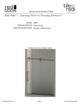
Figure 1 - Exploded View
Parts List
HA.3101 Part Box
1. HA.3001 - Roller Wheels ------------- 2
2. HA.3002 - Anti Jump Knobs --------- 2
3. HA.3003 - Bumper Stops ------------- 2
4. HA.3004 - Wall Collars / Pucks ----- 2
5. HA.3005 - Center Guide -------------- 1
6. HA.3007 - Panel Connectors ------- 2
7. BP.5001 - Part Bag --------------------- 1
7a - M6 - 1.75 X 60mm Screw ------ 2
7b - #10 X 1-1/8" 16tpi Screw ------- 1
7c - #10 X 1- 3/8" Wall Anchors ---- 1
7d - 6mm Allen Wrench --------------- 1
7e - 4mm Allen Wrench --------------- 1
7f - 3mm Allen Wrench ---------------- 2
Extra screws may
be provided for
your convenience
Page 3
1
2
4
4
14
15
13
11
7a
7a
6
6
5
3
3
16
12
9
8b
10
BP.5004.NTL - Part Bag
8a - BP.3027.SIL (Parts Kit) -------- 1 Bag
8b - BP.3028.NTL Setting Blocks- 1 Bag
8c - SP.2221.CLR Centering Clips ----- 3
8d - MM.5004 Inst. sheet ------------------ 1
7c
7b
For Wet Seal
For Dry Seal
Other Major Components
9. EX.1018 - Panel Sill -------------------- 1
10. VN.4031 - Snap Vinyl ------------------ 2
11. HA.30XX - Header Tube -------------- 1
12. VN.4304 - Soft Sill ---------------------- 1
13. VN.4083 - Vertical edge seal ---------1
14. Sliding Panel ----------------------------- 1
15. Fixed Panel ------------------------------- 1
16. HA.270X - 8” Handle ------------------- 1
8b
8c
OR
Full Size Drawings:
7a.
7b.
7c.

STEP 1 - Calculation:
* Measure height of sliding glass panels (14): ___________
* Subtract 3 1/16" from this measurement: ___________
* New measurement is the height from the threshold to the
center of the first Wall Puck Step 3.
STEP 4 - Mount First Wall Puck on “High Side” wall:
* Measure up from the threshold, the distance determined in
Step 1. Center Puck on the Centerline with the slot in the
vertical position and mark the hole location. See Detail B.
* Drill with a 3/16" drill bit. Enlarge hole through tile with
5/16” carbide bit to ensure screw will not crack tile.
* Install the Wall Puck (4 inside) with one M6 X 50mm screw,
(7a).
* Attach Wall Collar onto puck and tighten set screws to
secure Wall Collar, (4) in place.
* Sequence tightening of set screws as shown for best results.
Slider panel height - 3 1/16 = ______
B
Orient the
slot in Puck
vertically
when
securing.
High Side
Measurement
in Step 1
A
STEP 2 - Evaluate Threshold:
* Maximum recommended vertical threshold outage from
side to side is 1/4".
* If needed, mark high-side and low-side of threshold.
* First puck will be installed on high-side wall, or stationary
panel side if threshold is level.
* NOTE: Set sliding panel (14) inside shower before
proceeding.
Low (1/4” max)
High Side
Threshold
STEP 3 - Determine Centerline on Threshold and Walls:
* Mark Center Guide (5) location on threshold.
* To determine Centerline location, center the guide at center
of threshold width and depth.
Do not install! Location will shift during final adjustments.
* Wall pucks will be centered on the centerline of unit.
* Laser or plumb-bob is handy to determine and mark the
overall centerline of the unit. See Detail A
STEP 5 A - Check Header Tube Length:
* The header may already be cut to length from the factory
* To check measure wall to wall just below the Wall Pucks
and subtract 1 1/2". If your tube is this length, procede
to STEP 6. If not, procede to STEP 5B.
STEP 5 B - Cut Header Tube Length (figure C):
* Measure wall to wall just below the Wall Pucks
and subtract 1 3/4". This dimension will be the final length to
cut the header tube (11).
* IMPORTANT: The tube must be cut off from the end of the tube
that is furthest AWAY from the holes in the tube.
* Cut the tube to length with a hack saw.
Use 2” long
1/4” screw
C
Measure Wall to Wall just
below wall pucks subtract 1 3/4"
Wall Collar (4)
(orient cone
tipped set
screws into
puck)
Installation Instructions
Models: ECTE180 / ECSE180
3/8" Frameless Slider & 180° Panel
Page 4
Center
Guide (5)
set slider
panel (14)
Inside
shower
before
proceding
Cut from end that is opposite from the
holes in the tube
For STEP 5 B only

STEP 8 - Mount Second Puck on Opposite Wall:
* THIS STEP REQUIRES ASSISTANCE
- Carefully lift wall tube assembly and insert the open
tube end into the puck/collar already mounted on the wall
(high side).
- Take the second puck and hold it butted to the loose to
end of the header tube and against wall on the centerline.
- Level the tube with a level and mark the outline of the puck.
- Remove tube assembly and mark puck slot on the center-
line (keep slot vertical)
* Drill your mark with a 3/16" bit.
* Enlarge hole through tile with 5/16” carbide bit (to ensure
screw will not crack tile).
* Secure the Wall Puck (4) with one M6 X 50mm screw, (7a).
STEP 6 - Install Panel Connectors on Header Tube:
* Orient Header Tube (11) so that the two holes are facing up.
* Insert a screwdriver into the center hole of the tube.
* Slide a Plug into tube stopping it with the screwdriver.
* Manipulate the plug so that the hole in the plug lines up
with the hole in the tube.
* Put the screw through connector plate and into plug.
* Snug screws with the supplied Allen wrench.
* Repeat this procedure with the second hole closest to
the end of the tube. See Detail D.
D
Slide and manipulate plugs so
you can secure with connector
plates and screws.
Panel
Connector
Panel Connector (exploded)
Plug goes inside header tube.
Align threaded plug holes with holes in header
STEP 7 - Install Stoppers and Wall Collar on Header Tube:
* Carefully slide stopper to initial locations about 3” onto
the tube.
* Take care not to scratch the tube.
* Lightly tighten stopper set screw or secure with painter’s
tape so stoppers do not slide and scratch the tube.
* Final position will be determined during later steps.
* Opposite Side Wall Collar:
- Slide other wall collar onto the opposite side of tube.
See Detail E.
E
Stopper
Wall Collar
(orient cone
tipped set
screws into
puck)
Carefully slide stopper to initial locations about 3” onto the tube.
Take care not to scratch the tube.
Lightly tighten stopper set screw so they do not inadvertently slide.
Slide collar onto
tube and so
end is slightly
exposed
Orient the
slot in Puck
vertically
when
securing.
AlreadySecured
to wall
(High Side)
Position until level
and centered
Unit Centerline
Installation Instructions
Models: ECTE180 / ECSE180
3/8" Frameless Slider & 180° Panel
Page 5

STEP 9 - Mount Header Tube:
* Slide the Header Tube into wall collar with stoppers pointed
up.
* Slide the loose Wall Collar off the Header Tube and onto
the opposite Wall Puck taking care the tube does not fall.
* Center the Header tube within both Wall Collars and align
the Panel Fixers so they are facing to the outside.
* Secure tube by tightening the set screws on each collar in
the order shown (for best results).
Slide wall collar to right and
tighten set screws
Set Screw
Tightening Order
#1
#2
W
A
L
L
#4
#3
Cone Point
on Puck side
Cone Point
on Puck side
#1
#2
W
A
L
L
#4
#3
Cone Point
on Puck side
STEP 10 - Preparing and Positioning Bottom Channel:
* Prepare Bottom Channel (9):
- The Bottom Channel (9), may already be cut to size.
- If not, measure the width of the Fixed Glass Panel (15)
and subtract 3/4".
- Cut the EX.1018 Panel Sill, (9) to this length.
- Insert two 1/8" Clear Setting Blocks (8b).
* NOTE: Choose the Bottom Channel glazing method:
- DRY SEAL: Will use two pieces of Snap Vinyl after Glass
Panel is in final position.
OR
- WET SEAL: In addition to the Setting Blocks, also insert
three Centering Clips (8c) into the sill between setting blocks.
You will have to silicone glaze both sides of the panel to the
Bottom Channel after Panel is in final position.
* Position Bottom Channel:
- Butt bottom channel to wall in front of Centerline.
- Securely tape into position with blue painter’s tape on the
inside and outside to ensure it channel does not slip when
you put the panel in.
- NOTE: You will have to adjust the position of the channel
forward or backward during installation.
Cut the EX.1018 Panel Sill
Fixed Panel Width - 3/4”
Silicone
Bead
Centering
Clip (8c)
SP.2221
Wet Glazing
Parts Detail
Dry Glaze
Glazing Vinyl Detail
Snap Vinyl
Clip (10)
VN.4031
Setting
Blocks
(8b)
Choose Glazing Method
Bottom
Channel
Location:
butted to wall
in front of
Centerline
Installation Instructions
Models: ECTE180 / ECSE180
3/8" Frameless Slider & 180° Panel
Page 6

Page 5
STEP 11 - Mounting the Fixed Glass Panel:
* Set the Fixed Panel into the Panel Sill:
- Spaced panel 1/8" off of the wall.
- NOTE: 1/8” gap will be filled with silicone during final
steps of installation.
- The Fixed Panel will protrude out of the end of the
channel.
* Holes in the glass should line up with the two Panel
Connectors on the Header Tube.
* If they don't, you may have to raise or lower the Panel
by adjusting the Setting Blocks
* And / Or, adjust puck slot on the wall to raise or lower
Tube to adjust up and down and possibly rotate the Header
Tube to square it up to the panel.
* After the panel is adjusted, secure the Panel to the Header
Tube with Panel Connector Cap. Tighten securely using
Allen wrenches supplied.
* With the top of the Panel secured:
- Loosen blue tape
- Use a rubber mallet and tap the Panel Sill and the
panel at the bottom to the plumb position using a level.
* Securely tape bottom channel to floor with painter’s tape.
STEP 13 - Mounting the Sliding Panels:
* Take the Inside Sliding Panel (14), mount 2 Wheel
assemblies (1) as shown.
* NOTE:
The Wheel will face to the outside of the shower.
* By rotating plate between roller and glass, adjust the
roller so you have equal up and down adjustment.
* NOTE:
Once roller is adjusted to desired height, ensure
inner plate is not rotated.
*
Tighten the roller securely as shown by rotating back cap.
* Repeat for second roller (1). Tighten the rollers securely
using the two 3mm
Allen Wrenches (7f).
STEP 12 - Center Guide:
* Set the Center Guide (5) in place on the threshold and over
the edge of the Fixed Panel.
* NOTE: The Center Guide is reversible by loosening the
set screw and rotating the receiver.
- Open “C” without black insert cups over the exposed
edge of panel.
- Black insert side should point up and be positioned to the
inside of units as shown.
* Mark the hole location and drill with a 3/16” Drill bit. Insert
Wall Anchor (7c).
* Fill Wall Anchor and hole with silicone and put a bead on
the bottom of the Guide.
* Secure guide with one #8 X 1-1/8 FHPH Screw (7b).
1/8” Gap from wall will be
filled with silicone
Fixed Glass Panel
Adjust panel up or down
by adding or reducing
setting blocks in bottom
channel
Adjust panel forward
or backwards to make
panel plumb.
Blue
Painter's
Tape
Installation Instructions
Models: ECTE180 / ECSE180
3/8" Frameless Slider & 180° Panel
Page 7
3mm
Allen
Wrenches

STEP 14 - Hanging and Adjusting the Sliding Panel:
* From inside of the shower, carefully lift Sliding Panel (14)
onto the Header Tube (11) and into the Center Guide (5).
* Move each Bumper Stop (3) towards the walls.
* Shower Head Wall: bring the Sliding Panel to the closed
position, leaving an even 1/4”gap at the shower head wall.
* NOTE: you may have to individually adjust the rollers up
or down if wall and the edge of panel does not have equal
reveal from top to bottom.
* Secure bumper stop by tightening set screw located at the
top of the bumper stop. Tighten this well!
* Stationary Panel Wall: slide the sliding panel (14) to the
open position behind stationary panel (15).
* Slide the bumper stop to stop the roller:
- at least 1” from center of handle holes
OR
- so the back edge of sliding panel is 5/8” or more from
the wall.
- WHICHEVER HAPPENS FIRST
* Tighten second bumper stop well!
STEP 15 - Anti Jump Posts (2):
* Install Anti Jump Posts as shown.
* Adjust posts until they come within 1/16” of the bottom
of the bar.
* NOTE: Test to make sure the anti-jumps restrict the
rollers from coming off the tube.
* Tighten Anti-Jumb post securely, holding the back cap
in adjusted location.
STEP 17 - Final Glazing/Silicone: GE1200 Recommended
* Run a bead of Silicone vertically to seal the panel (15) to
the wall. Blue Painters tape is recommended to assist in
this step
* Install Snap Vinyl (10) or run a bead of Silicone along the
horizontial edge of the of bottom channel where it meets
the glass panel, and along the entire inside and outside of
threshold.
* Silicone gaps between center guide and glass.
* NOTE: Let silicone dry and tape cure for 24 hours
before use.
STEP 17 - Install Bumper Seal (13):
* Measure sliding panel top to bottem, deduct 1/8”
* Cut bumper seal (13) to this length and tap it
onto edge of sliding panel (14) on shower head side.
Installation Instructions
Models: ECTE180 / ECSE180
3/8" Frameless Slider & 180° Panel
Page 8
Rotate inside
plate on roller
to adjust up
or down
Tighten roller
by turning
back cap
Rotate
back cap to
adjust up
or down
Tighten
Anti-Jump
turning post.
STEP 16 - Install Handle (16):
* Install handle with instructions provided.
* Ensure handle does not hit stationary glass panel.
STEP 18 - Soft Sill (12):
* Measure from center guide to wall and deduct 1/16”
* Clean adhesion area under Soft Sill with alcohol
and dry.
* Cut Soft Sill to dimension. Peel the backing
off the tape on the sill and stick in place.
1/16”
gap
Outside
Bumper
Sea (13)
Handle
(16)
Soft Sill (12)
Fill 1/8” gap between stationary
panel and wall with silicone
Install Snap Vinyl
or silicone each side
of bottom channel
Silicone each side of bottom channel
and soft sill where it contacts threshold.
Silicone gaps
between center
guide and glass
/