Page is loading ...

Installation
Instructions
36” Vent Hood
ZV750, ZV755
Hotte Aspirante 36 po
Instructions d’installation
La section française commence à la page 19
Campana de ventilación de 36”
Instrucciones de instalación
La sección en español empieza en la página 37
31-10724-6
04-13 GE

2
Safety Information
BEFORE YOU BEGIN
Read these instructions completely and carefully.
•
IMPORTANT³ Save these instructions for
local inspector’s use.
•
IMPORTANT³Observe all governing codes
and ordinances.
• Note to Installer³ Be sure to leave these
instructions with the Consumer.
• Note to Consumer³ Keep these instructions
with your Owner’s Manual for future reference.
• Skill Level³ Installation of this appliance requires
basic mechanical and electrical skills.
• Completion Time³WR+RXUV
• Proper installation is the responsibility of the installer.
Product failure due to improper installation is not
covered under the warranty.
For Monogram local service in your area, call 1.800.444.1845.
For Monogram service in Canada, call 1.800.561.3344.
For Monogram Parts and Accessories, call 1.800.626.2002.
CAUTION:
Due to the weight and size of these vent hoods and
to reduce the risk of personal injury or damage to the
product, TWO PEOPLE ARE REQUIRED FOR PROPER
INSTALLATION.
WARNING:
To reduce the risk of fire or electrical shock, do not
use this range hood with any external solid-state speed
control device. Any such alteration from original factory
wiring could result in damage to the unit and/or create
an electrical safety hazard.
TO REDUCE THE RISK OF FIRE, USE ONLY METAL DUCTWORK.
WARNING: TO REDUCE THE RISK OF
FIRE, ELECTRICAL SHOCK OR INJURY TO PERSONS,
OBSERVE THE FOLLOWING:
A. Use this unit only in the manner intended by the
manufacturer. If you have any questions, contact the
manufacturer.
B. Before servicing or cleaning the unit, switch the
power off at the service panel and lock the service
disconnecting means to prevent the power from
being switched on accidentally. When the service
disconnecting means cannot be locked, securely
fasten a prominent warning device,such as a tag, to
the service panel.
CAUTION: FOR GENERAL VENTILATING
USE ONLY. DO NOT USE TO EXHAUST HAZARDOUS
MATERIALS, EXPLOSIVE MATERIALS OR VAPORS.
WARNING: TO REDUCE THE RISK OF
FIRE, ELECTRICAL SHOCK OR INJURY TO PERSONS,
OBSERVE THE FOLLOWING:
• Installation work and electrical wiring must be done
by qualified person(s) in accordance with all applicable
codes and standards, including fire-rated construction.
• Sufficient air is needed for proper combustion
and exhausting of gases through the flue (chimney)
of fuel burning equipment to prevent back-drafting.
Follow the heating equipment manufacturer’s
guidelines and safety standards, such as those
published by the National Fire Protection Association
(NFPA), the American Society for Heating, Refrigeration
and Air Conditioning Engineers (ASHRAE) and the local
code authorities. When applicable, install any makeup
(replacement) air system in accordance with local
building code requirements.
Visit GEAppliances.com for
available makeup air solutions.
• When cutting or drilling into walls or ceilings, do not
damage electrical wiring and other hidden utilities.
• Ducted systems must always be vented to the
outdoors.
• Local codes vary. Installation of electrical connections
and grounding must comply with applicable codes.
In the absence of local codes, the vent should be
installed in accordance with National Electrical Code
ANSI/NFPA 70-1990 or latest edition.
CAUTION: To reduce risk of fire and to
SURSHUO\H[KDXVWDLUEHVXUHWRGXFWDLURXWVLGH³GRQRW
vent exhaust air into spaces within walls or ceilings or
into attics, crawl spaces or garages.
READ AND SAVE THESE INSTRUCTIONS

3
Design Information
MODELS AVAILABLE
Model ZV750
Model ZV755
These hoods may be installed to vent to the outdoors,
or they may be installed for recirculating operation.
All necessary parts for recirculating operation are
supplied with the hood. No kits required.
• These vent hoods can be installed over any 30ļ or 36ļ
Monogram electric or gas cooktop except Monogram
Professional cooktops or ranges larger than 30ļ.
• Reversible duct covers accommodate recirculating
operation.
• The telescopic duct covers conceal the ductwork
running from the top of the hood to the ceiling.
• The supplied duct cover is sized to reach ceiling heights
up to 9’ or more, depending on the installation. See the
table on page 8.
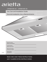
PRODUCT DIMENSIONS AND CLEARANCES
The vent hood must be installed 24ļ minimum, and
30ļ maximum above the cooking surface.
NOTE: Installation height should be measured from
the cooking surface to the lowest part of the hood.
=;6366'XFW&RYHU$FFHVVRU\
This accessory is available for installations with
ceiling heights above 9’ to 10’ and higher. See the table
on page 8.
The duct cover accessory must be on-site with the
hood at the time of installation.
*Height
to Ceiling
8-1/4"
27-1/2”
35-3/8″ (excluding utensil rods)
36-1/2″ (including utensil rods)
CONTENTS
Design Information
Models Available ................................................................................ 3
Product Dimensions ......................................................................... 3
Advance Planning
Ductwork Planning .......................................................................... 4
Wall Framing for Adequate Support ....................................... 4
Advance Planning ............................................................................ 4
Installation Preparation
Duct Fittings ......................................................................................... 5
Power Supply ...................................................................................... 6
Tools and Materials Required ...................................................... 6
Remove the Packaging ................................................................. 7
Check Installation Hardware ...................................................... 7
Determine Installation Height ..................................................... 8
Installation Instructions
Installation – Vented to the Outside ..................................9–13
Step 1, Install Framing for Hood Support .............................. 9
Step 2, Install Mounting Brackets ............................................10
Step 3, Install the Hood ................................................................10
Step 4, Install Duct Bracket ........................................................11
Step 5, Connect Ductwork ..........................................................12
Step 6, Connect Electrical ............................................................12
Step 7, Install Duct Cover and Utensil Rods .......................13
Step 8, Install Filters .......................................................................13
Step 9, Finalize Installation .........................................................13
Installation Instructions
Installation – Recirculating .................................................14–18
Step 1, Install Framing for Hood Support ............................14
Step 2, Install Mounting Brackets ............................................15
Step 3, Install the Hood ................................................................15
Step 4, Assemble Deflector and Connector ........................16
Step 5, Size Duct Piece ..................................................................16
Step 6, Install Air Deflector Assembly ....................................16
Step 7, Connect Electrical ............................................................17
Step 8, Install Duct Cover and Utensil Rods .......................17
Step 9, Install Filters .......................................................................18
Step 10, Finalize Installation.......................................................18
36ļ Minimum
24ļ Minimum
30ļ Maximum

Advance Planning
DUCTWORK PLANNING
• This hood is designed to be vented vertically
through the ceiling. Use locally supplied elbows
to vent horizontally through the rear wall.
• Determine the exact location of the vent hood.
• Plan the route for venting exhaust to the outdoors.
• Use the shortest and straightest duct route
possible. For satisfactory performance, duct run
should not exceed 10
Ļ equivalent length for any
duct configurations.
• Refer to “Duct Fittings” chart to compute the
maximum permissible length for duct runs to
the outdoors.
• Use rigid metal ductwork only.
• This vent hood must use a 6” round duct. The
6” round duct can transition to 3-1/4” x 10”
or 3-1/4” x 12”.
• Install the house duct to run horizontally between
ceiling joists or straight up through the roof.
• Install a wall or roof cap with damper at the
exterior opening. Order the wall or roof cap
and any transition and length of duct needed
in advance.
• When applicable, install any makeup (replacement)
air system in accordance with local building code
requirements.
Visit GEAppliances.com for available
makeup air solutions.
WARNING: TO REDUCE THE RISK OF
FIRE, USE ONLY RIGID METAL DUCTWORK.
WALL FRAMING FOR ADEQUATE
SUPPORT
• This vent hood is heavy. Adequate structural
support must be provided. The hood must be
secured to vertical studs in the wall. See page 9
or 14.
• We strongly recommend that the vent hood with
duct cover be on site before final framing and wall
finishing. This will also help to accurately locate the
ductwork and electrical service.
• Installation will be easier if the vent hood is
installed before the cooktop and countertop are
installed.
ADVANCE PLANNING
A duct cover accessory may be required for your
hood installation depending on ceiling height.
4

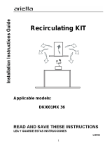
DUCT FITTINGS
This Hood Must Use an
6ļ Round Duct. It Can
7UDQVLWLRQWRļ[ļ
RUļ[ļ Duct.
Use this chart to compute
maximum permissible lengths
for duct runs to outdoors.
NOTE: Do not exceed maximum
permissible equivalent lengths!
Maximum duct length:
IRRWIRUUDQJHKRRGV
Flexible ducting:
If flexible metal ducting is used,
all the equivalent feet values in
the table should be doubled.
The flexible metal duct should
be straight and smooth and
extended as much as possible.
DO NOT use flexible plastic
ducting.
NOTE: Any home ventilation
system, such as a ventilation
hood, may interrupt the proper
flow of combustion air and
exhaust required by fireplaces, gas
furnaces, gas water heaters and
other naturally vented systems.
To minimize the chance of
interruption of such naturally
vented systems, follow the
heating equipment manufacturer’s
guidelines and safety standards
such as those published by NFPA
and ASHRAE. When applicable,
install any makeup (replacement)
air system in accordance with local
building code requirements.
Visit
GEAppliances.com for available
makeup air solutions.
5
Installation Preparation
Total Duct Run
* Actual length of straight duct plus duct fitting
equivalent. Equivalent length of duct pieces are
based on actual tests conducted by GE Evaluation
Engineering and reflect requirements for good
venting performance with any ventilation hood.
Total
Equivalent Quantity Equivalent
Duct Piece Dimensions Length* Used Length
Round, 1 ft. (per
straight foot length)
3-1/4ļ x 10ļ 1 ft. (per
straight foot length)
90° elbow 12 ft.
45° elbow 7 ft.
3-1/4ļ x 10ļ 14 ft.
3-1/4ļ x 12ļ 10 ft.
90° elbow
3-1/4ļ x 10ļ 8 ft.
3-1/4ļ x 12ļ 6 ft.
45° elbow
3-1/4ļ x 10ļ 33 ft.
3-1/4ļ x 12ļ 24 ft.
90° flat elbow
6ļ round to 2 ft.
rectangular
Rectangular to 8ļ 2 ft.
round
3-1/4ļ x 10ļ 4 ft.
3-1/4ļ x 12ļ 4 ft.
6ļ round to rectangular
transition 90° elbow
3-1/4ļ x 10ļ 4 ft.
3-1/4ļ x 12ļ 4 ft.
Rectangular to 6ļround
transition 90° elbow
Round wall cap 24 ft.
with damper
3-1/4ļ x 10ļ 24 ft.
3-1/4ļ x 12ļ 18 ft.
Rectangular wall cap
with damper
Round roof cap 33 ft.

Masking
tape
Gloves
Utility Knife
6
POWER SUPPLY
IMPORTANT – (Please read carefully)
WARNING:
FOR PERSONAL SAFETY, THIS APPLIANCE MUST
BE PROPERLY GROUNDED.
Remove house fuse or open circuit breaker before
beginning installation.
Do not use an extension cord or adapter plug with
this appliance. Follow National Electrical Code or
prevailing local codes and ordinances.
Electrical supply
This vent hood must be supplied with 120V, 60Hz,
and connected to an individual, properly grounded
branch circuit, and protected by a 15- or 20-amp
circuit breaker or time-delay fuse.
• Wiring must be 2-wire with ground.
• If the electrical supply does not meet the above
requirements, call a licensed electrician before
proceeding.
• Route house wiring as close to the installation
location as possible. Wiring can enter from the
ceiling or rear wall. Route additional length from
the ceiling or wall to reach the junction box.
• Connect the wiring to the house wiring in
accordance with local codes.
Grounding instructions
The grounding conductor must be connected to
a ground metal, permanent wiring system, or an
equipment-grounding terminal or lead on the hood.
WARNING: The improper connection
of the equipment-grounding conductor can result
in a risk of electric shock. Check with a qualified
electrician or service representative if you are in
doubt whether the appliance is properly grounded.
TOOLS AND MATERIALS REQUIRED
(NOT SUPPLIED)
Pliers
Wire cutter/stripper
Metal snips
Spirit level
Aluminized
duct tape
Safety glasses
120V 60Hz. 15- or 20-Amp,
2-wire with ground, properly
grounded branch circuit
Stepladder
Saber saw or Key Hole saw
Phillips screwdriver
Strain relief for
junction box
6ļ round metal
duct, length to
suit installation
Hammer
Electric drill with 1/8ļ bits,
#2 Phillips and flat head
Flashlight
UL-listed wire nuts
Pencil and tape measure
Installation Preparation

CHECK INSTALLATION HARDWARE
Locate the hardware accessory box packed with
the hood and check contents.
3 charcoal filters
Air deflector with
upper duct connector
• Drill 1/8" Pilot Holes For Mounting Brackets.
Align edge 25-1/2" above Cooking Surface.
17-5/16"
3-15/16"
13-9/16"
2-5/32"
C
L
• Drill 1/8" Pilot Holes.
• Drill 1/8" Pilot Holes.
5-7/8"
Wall-mount template
10 wood
screws
10 metal wall
fasteners
2 Large
flat washers
2 Mounting brackets
3 Stainless
steel grease
filters
Decorative
duct covers
Duct cover bracket (not
required for recirculating
operation)
2 Phillips-
head duct
cover screws
2 Utensil rods with 4 machine screws
Additional Parts for Recirculation Operation
7
Installation Preparation
REMOVE THE PACKAGING
CAUTION: Wear gloves to protect
against sharp edges.
The vent hood is shipped secured to a shipping
board with 4 screws.
• Remove the duct cover, parts box and foam
packaging.
• Lift the hood out of the box.
• Remove and properly discard the plastic wrapping.
• Remove metal grease filters and side bar packaging.
• To remove the shipping board, locate and remove
2 screws at the top of the assembly and 2 screws
inside the hood behind the filter guides on the left
and right sides. Discard the shipping board.
• Remove junction box cover.
• Remove knockout from junction box.
• Install strain relief onto junction box.
Mounting screw
Shipping board
Shipping board
Mounting screw
Mounting
screw
Knockout
Junction box
NOTE: Additional tools, materials and hardware are
required to construct your wall framing support.

=9=9,QVWDOODWLRQ+HLJKWV
Upper (Inner) Duct Cover (B) 24.25ļ
Lower (Outer) Duct Cover (A) 18.5ļ
Accessory Lower (Outer) Duct Cover (A) 31.5ļ
Actual *VENTED *RECIRCULATING
Ceiling Installation Installation
Height Height Height
7Ļ 24”to 28” 24”to 28”
8Ļ 0” 24” to 29” 24” to 29”
8Ļ 1” 24” to 30” 24” to 30”
8Ļ 2” 24” to 30” 24” to 30”
8Ļ3” 24” to 30” 24” to 30”
8Ļ 4” 24” to 30” 24” to 30”
8Ļ 5” 24” to 30” 24” to 30”
8Ļ 6” 24” to 30” 24” to 30”
8Ļ 7” 24ļ to 30” 24” to 30”
8Ļ 8” 24” to 30” 24” to 30”
8Ļ 9” 25” to 30” 24” to 30”
8Ļ 10” 26” to 30” 24” to 30”
8Ļ 11” 27” to 30” 24” to 30”
9Ļ 0” 28” to 30” 2” to 30”
9Ļ 1” 29”to30” 25” to 30”
9Ļ 2” 30” 26” to 30”
9Ļ 3” 27” to 30”
9Ļ 4” 28” to 30”
9Ļ 5” 29” to 30”
9Ļ 6” 30”
9Ļ 0ļ 24ļ to 30ļ 24ļ to 28ļ
9Ļ 1ļ 24ļ to 30ļ 24ļ to 29ļ
9Ļ 2ļ 24ļ to 30ļ 24ļ to 30ļ
9Ļ 3ļ 24ļ to 30ļ 24ļ to 30ļ
9Ļ 4ļ 24ļ to 30ļ 24ļ to 30ļ
9Ļ5ļ 24ļ to 30ļ 24ļ to 30ļ
9Ļ 6ļ 24ļ to 30ļ 24ļ to 30ļ
9Ļ 7ļ 24ļ to 30ļ 24ļ to 30ļ
9Ļ 8ļ 24ļ to 30ļ 24ļ to 30ļ
9Ļ 9ļ 24ļ to 30ļ 24ļ to 30ļ
9Ļ 10ļ 25ļ to 30ļ 24ļ to 30ļ
9Ļ 11ļ 26ļ to 30ļ 24ļ to 30ļ
10Ļ 0ļ 27ļ to 30ļ 24ļ to 30ļ
10Ļ 1ļ 28ļ to 30ļ 24ļ to 30ļ
10Ļ 2ļ 29ļ to 30ļ 24ļ to 30ļ
10Ļ 3ļ 30ļ 25ļ to 30ļ
10Ļ 4ļ 26ļ to 30ļ
10Ļ 5ļ 27ļ to 30ļ
10Ļ 6ļ 28ļ to 30ļ
10Ļ 7ļ 29ļ to 30ļ
10Ļ 8ļ 30ļ
*Based on 36ļ countertop height.
Installation Preparation
DETERMINE INSTALLATION HEIGHT
• Telescopic duct covers are provided to conceal
the ductwork running to the ceiling.
• This hood can be installed for vented or
recirculating operation. All necessary parts are
shipped with the hood.
NOTE: Installation height should be measured from
the cooking surface to the bottom of the hood.
The vent hood must be installed 24ļ min. and
30ļ max. above the cooking surface. The hood
installation height, from the cooking surface to the
bottom of the hood, depends upon ceiling height
and duct cover limitations.
24” Min.
30” Max.
36" Min.
DUCT COVER DIMENSIONS
=;6366'XFW&RYHU$FFHVVRU\
This accessory is available for installation with
ceiling heights above 9 feet to 10 feet and higher.
This accessory consists of one 31-1/2ļlower duct
cover.
ACCESSORY ZX90010 SUPPLIED
ZX7510SPSS (Need Accessory Lower Duct Cover 31.5ļ)
8
9-1/4ļ
11-7/8ļ

9
INSTALL FRAMING FOR HOOD
SUPPORT
IMPORTANT³The vent hood must be
secured to rear support framing or a wall stud.
)UDPLQJPXVWEHFDSDEOHRIVXSSRUWLQJOEV
If drywall is present, mark the screw hole locations
for the top mounting brackets. Remove the template.
• Cut away enough drywall to expose 2 vertical studs
at the bracket location indicated on the template.
• Install a horizontal support at least 1ļ x 12ļ
between two wall studs at the mounting screw
location. The horizontal support must be flush with
the room side of the studs. Use cleats behind both
sides of the support to secure to wall studs.
IMPORTANT: Reinstall drywall for an even mounting
surface.
Installation Instructions
View from
rear cleats
1ļ x 12ļ min.
mounting
support
DUCTWORK, WIRING LOCATIONS
Determine the exact location of the vent hood.
• Locate the template packed with the literature.
–Measure 36ļ from the floor to the top of the
cooking surface. Add hood installation height
determined on page 8. Mark that location.
–Use a level to draw a straight pencil line on the wall.
–Tape the template in position along the penciled
line. CHECK TO BE SURE THE TEMPLATE IS LEVEL.
Ceiling ducting:
If ductwork will vent straight up to the ceiling:
• Use a level to draw a line straight up, from the
centerline on the template to the ceiling.
• Measure 3-3/4ļ from the back wall to the centerline
of an 6-1/2ļ hole on the ceiling.
NOTE: If drywall is not present, add drywall thickness
to the 3-3/4ļ dimension.
Wall Ducting:
If ductwork will vent to the rear:
• Use a level to draw a line straight up from the
centerline on the template.
• Measure at least 6ļ above the bracket location shown
on the template to the centerline of a 6-1/2ļ-dia. duct
hole. (Hole may be elongated for duct elbow.)
HOUSE WIRING LOCATION:
• The junction box is located on the top left side of the
hood.
• Wiring can enter from the back wall or ceiling above
the top bracket location. Route additional wiring
length to reach the junction box.
INSTALLATION – VENTED TO THE OUTSIDE
6-1/2ļ min. opening for
ductwork
• Drill 1/8" Pilot Holes For Mounting Brackets.
Align edge 25-1/2" above Cooking Surface.
17-5/16"
3-15/16"
13-9/16"
2-5/32"
C
L
• Drill 1/8" Pilot Holes.
• Drill 1/8" Pilot Holes.
5-7/8"
FOR WALL
VENT DUCT
Centerline 6
ļ
min.
above bracket location
FOR CEILING VENT
DUCTING
3-3/4ļ c enterline to wall
Centerline of
installation
space
NOTE: 2 horizontal supports
will be needed if there is a
stud located between the
horizontal screw locations.

10
INSTALL MOUNTING BRACKETS
The vent hood must be secured to rear support framing
or a wall stud.
• With the template taped in place, use a punch to mark all
mounting screw locations.
• Drill 1/8ļ pilot holes at the 6 punched locations.
• Remove the template.
• Enlarge holes that did not enter studs to 3/8ļ and tap
anchors for wall fasteners into the holes.
– Drive screws into the fasteners to allow anchors to
expand against the wall material. Remove the screws
for final installation.
• Secure the mounting brackets to the wall studs with
wood screws provided.
Installation Instructions
INSTALLATION – VENTED TO THE OUTSIDE
NOTE: Screws “A” and “B” are preassembled onto the
brackets. Do not remove these screws.
3
INSTALL THE HOOD
Place the hood on the brackets and slide left to right to align
with rectangular slots at the top.
• Adjust the installation height by tightening or loosening the
screws “A” at the bottom of the brackets.
• Align the hood lower mounting holes with pilot holes in
the wall.
• Using two large washers (supplied), install wood screws or
wall-fastener screws, loosely, into lower mounting holes.
Do not tighten.
• Level the hood by tightening or loosening the screws “A”
located on the bottom mounting brackets.
• Tighten the lower mounting screws.
• Tighten screws “B” located at the top of the mounting
bracket against the hood to adjust position. Do not
overtighten screws.
Screws “B” to adjust
hood against wall
Level and
height
adjustment
screws “A”
Lower mounting
screws
Screws “B”
Screws “A”

11
Installation Instructions
INSTALLATION – VENTED TO THE OUTSIDE
INSTALL DUCT BRACKET
VENTING TO THE REAR (HORIZONTAL EXHAUST)
OR STRAIGHT UP TOP (VERTICAL EXHAUST)
• Temporarily install the 2 small screws into the sides
of the duct bracket. Remove the screws. This will
ensure ease of final installation.
• Position the upper duct bracket against the wall and
ceiling, aligned with CL pencil mark and CL on the
bracket.
• Mark the 4 screw locations of the bracket.
• Remove the bracket.
• Drill 1/8ļ pilot holes in marked bracket location.
• If pilot holes do not enter studs, enlarge the holes 3/8ļ
and install wall-fastener anchors. Drive screws into the
fasteners to allow anchors to expand against the wall
material. Remove the screws.
• Secure the bracket to the ceiling and wall with wood
screws and/or wall-fastener screws.
Top or
vertical
exhaust
Rear or
horizontal
exhaust
Duct bracket

12
Installation Instructions
INSTALLATION – VENTED TO THE OUTSIDE
5
CONNECT DUCTWORK
• Remove shipping tape from the damper.
• Install ductwork, making connections
in the direction of airflow as illustrated.
• Push duct over the exhaust outlet and damper.
CAUTION: Do not use sheet metal
screws at the exhaust outlet connection. Doing
so will prevent proper damper operation. Seal
connection with tape only.
• Secure joints in ductwork with sheet metal screws.
• Wrap all duct joints and the flange connections
with aluminized duct tape for an airtight seal.
Duct tape
over seam
and screw
Screw
Airflow
6 CONNECT ELECTRICAL
Verify that power is turned off at the source.
WARNING: If house wiring is not 2-wire
with a ground wire, a ground must be provided
by the installer. When house wiring is aluminum,
be sure to use U.L.-approved antioxidant compound
and aluminum-to-copper connectors.
• Remove the junction box cover and the selected
knockout.
• Secure the house wiring to the junction box with
a strain relief (not provided).
• Connect the white lead to the branch circuit white lead.
• Connect the black lead to the branch circuit black lead.
• Connect the green/yellow lead to the branch
circuit green lead or bare ground lead.
• Secure all the connections with wire nuts on each
electrical connector.
• Push the wires into the junction box and replace
the cover. Be sure the wires are not pinched.
• Secure the junction box cover with the 2 original
screws.
Junction
box cover
Knockout

13
Installation Instructions
INSTALLATION – VENTED TO THE OUTSIDE
7
INSTALL DUCT COVER AND
UTENSIL RODS
Assemble the duct covers
as shown.
For this vented installation,
place upper duct piece
inside the lower duct piece.
The inner duct cover venting
holes should be positioned
toward the bottom end and
should not be visible.
• Insert the assembled duct
covers into the impression
on the top of the hood.
• Extend the inner duct
cover upwards to meet
the ceiling and bracket.
(The vent holes should not
be visible in this installation.)
• Secure the duct cover to the bracket with the 2 small
duct cover screws provided.
• Install the side utensil rods as shown with screws
provided.
,QVWDOORSWLRQDODFFHVVRU\=;6366
(if needed to reach taller ceiling heights)
• Separate the supplied duct cover into pieces. Discard
the lower (outer) section.
•
Slide the new ZX7510SPSS duct cover onto the original
upper section. Be sure that the longer section is outside
the shorter original section. The notches will be at the
bottom and the screw holes at the top as illustrated.
• Secure the duct cover to the bracket with the 2 small
duct cover screws provided.
Mounting Screws
Bottom
Notche
s
8
INSTALL FILTERS
•
Remove protective film on filters.
• T
ip the filter into the lower channel at the rear of the
opening, push back, lift and pull the knob forward until
the filter rests on the channel.
•
Install all three metal grease filters.
•
Turn power on. If the filter light on the control
panel glows, adjust the right-side filter in the
channel to engage the switch arm.
Lower charcoal
filter channel
Lower
filter slots
9
FINALIZE INSTALLATION
•
Remove protective film covering the control panel
on the front face of the hood and any remaining
packaging materials.
•
Make sure the filters are seated properly when
installed and the filter light is not on.
•
Be sure fan and lights operate correctly. Refer to
the Owner’s Manual for operating instructions and
Problem Solver.

14
Installation Instructions
INSTALLATION – RECIRCULATING
DUCTWORK, WIRING LOCATIONS
• Determine the exact location of the vent hood.
• Locate the template packed with the literature.
• Measure 36ļ from the floor to the top of the cooking
surface. Add hood installation height determined on
page 8. Mark that location.
• Tape the template in position along the penciled line.
CHECK TO BE SURE THE TEMPLATE IS LEVEL.
• Use a level to draw a line straight up, from
the centerline on the template to the ceiling.
HOUSE WIRING LOCATION:
• The junction box is located on the top left side
of the hood.
• Wiring can enter from the back wall or ceiling above
the top bracket location. Route additional wiring
length to reach the junction box.
INSTALL FRAMING FOR
HOOD SUPPORT
IMPORTANT: The vent hood must be
secured to rear support framing or a wall stud.
)UDPLQJPXVWEHFDSDEOHRIVXSSRUWLQJOEV
If drywall is present, mark the screw hole locations
for the top mounting brackets. Remove the template.
• Cut away enough drywall to expose 2 vertical studs
at the bracket location indicated on the template.
• Install a horizontal support at least 1ļ x 12ļ
between two wall studs at the mounting screw
location. The horizontal support must be flush with
the room side of the studs. Use cleats behind both
sides of the support to secure to wall studs.
IMPORTANT: Reinstall drywall for an even mounting
surface.
View from
rear cleats
1ļ x 12ļ min.
mounting
support
Centerline of
installation
space
• Drill 1/8" Pilot Holes For Mounting Brackets.
Align edge 25-1/2" above Cooking Surface.
17-5/16"
3-15/16"
13-9/16"
2-5/32"
C
L
• Drill 1/8" Pilot Holes.
• Drill 1/8" Pilot Holes.
5-7/8"
NOTE: 2 horizontal supports
will be needed if there is a
stud located between the
horizontal screw locations.

15
Installation Instructions
INSTALLATION – RECIRCULATING
INSTALL MOUNTING BRACKETS
The vent hood must be secured to rear support framing
or a wall stud.
• With the template taped in place, use a punch to mark all
mounting screw locations.
• Drill 1/8ļ pilot holes at the 6 punched locations.
• Remove the template.
• Enlarge holes that did not enter studs to 3/8ļ and tap
anchors for wall fasteners into the holes.
– Drive screws into the fasteners to allow anchors to
expand against the wall material. Remove the screws
for final installation.
• Secure the mounting brackets to the wall studs with
wood screws provided.
NOTE: Screws “A” and “B” are preassembled onto the
brackets. Do not remove these screws.
3
INSTALL THE HOOD
Place the hood on the brackets and slide left to right to align
with rectangular slots at the top.
• Adjust the installation height by tightening or loosening the
screws “A” at the bottom of the brackets.
• Align the hood lower mounting holes with pilot holes in the
wall.
• Using two large washers (supplied), install wood screws or
wall-fastener screws, loosely, into lower mounting holes.
Do not tighten.
• Level the hood by tightening or loosening the screws “A”
located on the bottom mounting brackets.
• Tighten the lower mounting screws.
• Tighten screws “B” located at the top of the mounting
bracket against the hood to adjust position. Do not
overtighten screws.
Screws “B” to adjust
hood against wall
Level and
height
adjustment
screws “A”
Lower mounting
screws
Screws “B”
Screws “A”

16
Installation Instructions
INSTALLATION – RECIRCULATING
ASSEMBLE DEFLECTOR
AND CONNECTOR
A The duct connector is shipped
inside the deflector.
B Snap the plastic connector out
of the deflector and remove.
C Turn over the plastic
connector. From the bottom,
snap the connector over the
opening as shown.
6
INSTALL AIR DEFLECTOR ASSEMBLY
• Place the assembly
over the hood
outlet.
• Hold the assembly
against the ceiling.
The penciled
centerline should
show through
the slot on the
deflector. Mark
the two screw
holes on the back
of the assembly.
• Remove the
assembly and drill
1/8ļ pilot holes into
the wall studs.
• Enlarge holes that did not enter studs to 3/8ļ and
tap plastic or metal anchors into the holes, flush
with the wall.
• Mount the assembly onto the hood outlet, push
up against the ceiling and install the screws
provided.
• Use duct tape to seal the connection.
CAUTION: Do not use sheet metal
screws at the hood duct flange connection. Doing
so will prevent proper damper operation. Seal
connections with tape only.
A
Remove plastic connector
B
Snap into place
C
5
SIZE DUCT PIECE
• Hold air deflector
with duct
connector against
the ceiling. Align
window on the
back of the
deflector with the
marked centerline.
• Measure from
the bottom of
the deflector to
the top of the
hood as shown.
Reduce this dimension by
1ļ to facilitate installation.
The duct will cover/overlap
the duct connector and the
exhaust outlet.
• Cut the duct piece to size
and slip onto the bottom of
the duct connector.
• Use duct tape to secure the
duct piece to the connector.
• Temporarily install the
2 small duct cover screws
into the sides of the deflector. Remove the screws.
This will ensure ease of final installation.
Centerline
Duct
length
Measure
length
Screws
Air deflector assembly

17
Installation Instructions
INSTALLATION – RECIRCULATING
7 CONNECT ELECTRICAL
Verify that power is turned off at the source.
WARNING: If house wiring is not 2-wire
with a ground wire, a ground must be provided
by the installer. When house wiring is aluminum,
be sure to use U.L. approved antioxidant compound
and aluminum-to-copper connectors.
• Remove the junction box cover and the selected
knockout.
• Secure the house wiring to the junction box with
a strain relief.
• Connect the white lead to the branch circuit white lead.
• Connect the black lead to the branch circuit black lead.
• Connect the green/yellow lead to the branch
circuit green lead or bare ground lead.
• Secure all the connections with wire nuts on each
electrical connector.
• Push the wires into the junction box and replace
the cover. Be sure the wires are not pinched.
• Secure the junction box cover with the 2 original
screws.
8
INSTALL DUCT COVERS AND
UTENSIL RODS
• Assemble the duct covers as shown.
For this recirculating installation, the vent holes must
be positioned at the top. The vent holes must be fully
exposed to allow airflow into the room.
• Insert the duct cover assembly into the impressions
on the top of the hood.
• Extend the inner duct cover upwards to meet the
ceiling and support frame.
,QVWDOORSWLRQDODFFHVVRU\=;6366
(if needed to reach taller ceiling heights)
• Separate the supplied duct cover. Discard the lower
(outer) section.
• Slide the new ZX7510SPSS duct cover into the
original upper section. Be sure that the vent holes are
positioned toward the top.
• Insert the duct cover assembly into the impressions
on the top of the hood.
• Secure the duct cover at the top to the air deflector
with 2 screws provided.
• Install the side utensil rods as shown with screws
provided.
Junction
box cover
Knockout
Mounting screw holes

18
Installation Instructions
INSTALLATION – RECIRCULATING
9
INSTALL FILTERS
• There are two channels inside the back and front of the
hood. These channels will hold the charcoal filters and
stainless steel grease filters in place.
Install charcoal filters
• Remove protective film on the charcoal filters.
• Tip charcoal filters into the upper (top) channels at the
rear of the opening. Grasp the filter tab, lift and pull
forward until it rests in the front upper channel.
• Install all 3 charcoal filters.
Install grease filters
• Remove protective film from grease filters.
• Tip the grease filter into the lower channel at the
rear of the opening. Push back, lift and pull the knob
forward until the filter rests on the channel.
• Install all 3 grease filters.
• Turn power on. If the filter light on the control panel
glows, adjust the right-side filter in the channel to
engage the switch arm.
Upper charcoal
filter channel
Grasp tab,
lift and pull forward
Lower charcoal
filter channel
Upper charcoal
filter channel
Lower
filter slots
FINALIZE INSTALLATION
• Remove protective film covering the control panel
on the front face of the hood and any remaining
packaging materials.
• Make sure the filters are seated properly when
installed and the filter light is not on.
• Be sure fan and lights operate correctly. Refer to
the Owner’s Manual for operating instructions and
Problem Solver.

31-10724-6
04-13 GE
Printed in Italy
Imprimé en Italie
Impreso en Italia
NOTE: While performing installations described in this book,
safety glasses or goggles should be worn.
For Monogram
®
local service in your area,
call 1.800.444.1845.
NOTE: Product improvement is a continuing endeavor
at General Electric. Therefore, materials, appearance
and specifications are subject to change without notice.
NOTE : Il est recommandé de porter des lunettes de
sécurité ou des lunettes étanches lors de l’installation de cet
appareil.
Pour les services locaux Monogram
®
dans votre
secteur, appelez le 1.800.444.1845.
NOTE : Au sein de General Electrics, nous nous efforçons
toujours d’améliorer nos produits. Ainsi, les matériaux,
l’aspect et les spécifications peuvent être modifiés sans
préavis.
NOTA: Mientras efectúa las instalaciones descriptas
en este libro, deben utilizarse gafas o lentes de seguridad.
Para servicio técnico local Monogram
®
en su área,
llame al 1.800.444.1845.
NOTA: La mejora de los productos es un esfuerzo
continuo para General Electric. Por lo tanto, los materiales,
la apariencia y las especificaciones pueden sufrir
cambios sin previo aviso.
GE Appliances & Lighting
Appliances
General Electric Company
Louisville, KY 40225
GEAppliances.com
/