GE Stainless Steel Range Hood User manual

Category
Cooker hoods
Type
User manual

This manual is also suitable for

PUB # 31-9043 03/00
MODEL SERIES:
TECHNICAL SERVICE GUIDE
GE Consumer Service Training
Monogram® Wall-Mounted
and Island Hoods
ZV750
ZV850
IMPORTANT SAFETY NOTICE
The information in this service guide is intended for use by
individuals possessing adequate backgrounds of electrical,
electronic, and mechanical experience. Any attempt to repair a
major appliance may result in personal injury and property
damage. The manufacturer or seller cannot be responsible for the
interpretation of this information, nor can it assume any liability in
connection with its use.
CAUTION
To avoid personal injury, disconnect power before servicing this
product. If electrical power is required for diagnosis or test
purposes, disconnect the power immediately after performing the
necessary checks.
RECONNECT ALL GROUNDING DEVICES
If grounding wires, screws, straps, clips, nuts, or washers used
to complete a path to ground are removed for service, they must
be returned to their original position and properly fastened.
GE Consumer Service Training
Technical Service Guide
Copyright © 2000
All rights reserved. This service guide may not be reproduced in whole or in part
in any form without written permission from the General Electric Company.
!
– 1 –
Table of Contents
Hood Nomenclature ............................................................................................ 2
Features ...............................................................................................................3
Installation Highlights.........................................................................................3
Controls ...............................................................................................................5
Use and Care Information .................................................................................. 8
Halogen Lamp Assembly Replacement ............................................................ 9
Filter Replacement .............................................................................................. 9
Component Access/Duct Cover Removal......................................................... 9
Control PCB Replacement ................................................................................. 10
Entry/Display Assembly Replacement ..............................................................11
Filter Microswitch Replacement1 ...................................................................... 11
Fuse Replacement ..............................................................................................12
Glass Visor Replacement ...................................................................................12
Motor & Blower Assembly Replacement .......................................................... 13
Motor Capacitor Replacement ........................................................................... 14
Transformer Replacement.................................................................................. 15
Triac Replacement ..............................................................................................16
Troubleshooting .................................................................................................. 17
Schematic & Strip Circuits ................................................................................. 18
Model ZV750 Illustrated Parts Breakdown .......................................................22
Model ZV850 Illustrated Parts Breakdown .......................................................24
Warranty Information ..........................................................................................27
– 2 –
Hood Nomenclature
ZV850
ZV750
*Duct covers are available as necessary accessory kits to accomodate installations with 8-, 9-, or 10-foot ceilings.
GEA00028
25-1/2" Recommended
36" Reference
Height
to Ceiling
*
8-1/4"
35-3/8" 27-1/2"
Nomenclature
Mini Manual
Locator Label
Nomenclature
25-1/2" Recommended
36" Min.
GEA0002
7
Mini Manual
Locator Label
Height to Ceiling*
ZV750Y1: Early model wall-mounted hood.
ZV750Y2: Later model wall-mounted hood with motor
mount similar to Island-mounted hood.
– 3 –
Installation Highlights
Mount Dimensions and Clearances
(See Hood Nomenclature)
The vent hood must be installed at least 24 inches and not more than 30 inches above the cooking surface.
25-1/2 inches is recommended to ensure that the duct cover meets the ceiling. The cooking surface should
be at least 36 inches above the floor.
Electrical Wiring
WARNING: Remove house fuse or open circuit breaker before beginning installation. Do not use an
extension cord or adapter plug with this appliance. Follow national electrical codes or prevailing local codes
and ordinances.
Electrical Supply
The vent hood must be supplied with 120V, 60Hz electrical power, and connected to an individual, properly
grounded branch circuit, protected by a 15- or 20-ampere circuit breaker or time delay fuse.
• Wiring must be 2-wire with ground.
• If electrical supply does not meet the above requirements, call a licensed electrician before proceeding.
• Route wiring as close to the installation location as possible, in the ceiling or soffit.
• Connect the wiring to the house wiring in accordance with local codes.
Features
Stainless Steel Finish
36-Inch Width
350 CFM Vertical Exhaust Blower Rating
Electronic Touchpad Controls
4 Halogen Lamps
3 Removable Filters with 30-Hour Filter Cleaning Reminder
6-Inch Round Duct
Model ZV750 Wall Mount
Model ZV850 Island Mount
– 4 –
Grounding Instruction
WARNING: The improper connection of the equipment-grounding conductor can result in a risk of electric
shock. Check with a qualified electrician if you are in doubt whether the appliance is properly grounded.
The grounding conductor must be connected to a metal ground, permanent wiring system, or an
equipment-grounding terminal or lead on the hood.
Exhaust Ducting
The hood uses 6-inch metal ducting to exhaust fumes. Refer to the vent hood installation instructions for
details of the maximum permissable lengths to be used for duct runs to outdoors. Do not exceed the
maximum permissable equivalent length total of 100 feet for a range hood.
Flexible 6-inch metal ducting may be used. When flexible ducting is used, all equivalent feet values of
components must be doubled. The flexible metal duct should be straight and smooth and extended as
much as possible. Do not use flexible plastic ducting.
Note: Any home ventilation system, such as a ventilation hood, may interrupt the proper flow of combus-
tion air and exhaust required by fireplaces, gas furnaces, gas water heaters, and other naturally vented
systems. To minimize the chance of interruption of such naturally vented systems, follow the heating
equipment manufacturer’s guidelines and safety standards such as those published by NFPA and ASHRAE.
Install all ductwork by making joint connections
in the direction of the air flow as illustrated.
Secure the joints with sheetmetal screws. Wrap
the joints with duct tape for an airtight seal.
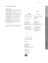
Model ZV 850
This model is installed using 1 of 3 installation
kits (for 8-, 9-, or 10-foot ceilings). The upper
support frame (shown at right) is secured to the
ceiling joists and/or cross framing with 4 screws.
The support frame must be level and square.
The lower support frame slips into the upper
frame and can be adjusted up or down to the
desired height. It is secured with 8 screws and
washers.
Support
Frame
Opening
Upper
Support
Frame
Lower
Support
Frame
Check Level
in
Both Directio
n
Front
Of
Hood
GEA00116
– 5 –
Controls
CONTROLS CONFIGURATION
Fan Keypad Operation
1. ON/OFF Switch - Turns electrical power to motor on and off. Remembers the last fan speed used.
2. Decrease Speed - Decreases current fan speed (4 speeds).
3. Increase Speed - Increases current fan speed (4 speeds).
4. High Speed - Maximum fan speed (350 cfm).
5. Delayed Shut-off - Choose 5-, 10-, or 20-minute shutdown time by pushing this button. Time is
indicated by illumination of Delay Shut-off Indicators (10).
Hood Lights Keypad Operation
6. Light ON/OFF - Turns electrical power to light on and off. Remembers the last light level used.
7. Decrease Brightness - Dims lights in 6 light levels.
8. Increase Brightness - Brightens lights in 6 light levels.
Display LEDs
9. Filter Cleaning Reminder Indicator - Lights after 30 hours of “on” time to remind you to clean the
metal grease filters. The light blinks until the filters are replaced. The timer resets automatically.
10. Delayed Shut-off Indicators - Indicates delayed time setting. The fan will shut off automatically at the
end of the delayed time setting.
11. Fan Operating Symbol - When illuminated, indicates that the fan is in operation even if the noise of
the fan cannot be heard.
1234910
11
5678
05
10
20
10
11
9
GEA0001
4
– 6 –
ELECTRONIC HOOD CONTROL DESCRIPTION
The electronic hood control system consists of the following parts: Entry/Display Assembly; Control PCB;
Triac; Fuse Holder; Motor Capacitor; Transformer; Halogen Lamps; Filter Microswitch; and Induc-
tion Fan Motor.
CAUTION: Components are electrically HOT on the electronic control when voltage is connected to the
hood even though the ON/OFF switch is in the OFF position.
1. ENTRY/DISPLAY ASSEMBLY
The replacement assembly WB27X10345 has 3 Printed Circuit Boards (PCB) mounted in a plastic enclo-
sure with 8 push buttons and a ribbon cable. The three PCBs are Fan Touch Control PCB, Lamp Touch
Control PCB, and Display PCB.
Note: Before replacing the assembly, check the operation of the other hood components by plugging the
new Entry/Display Assembly cable into connector CN5 on the Control PCB. If the unit does not work,
replace the control board first and then recheck whether the existing Entry/Display assembly is OK. The
harness in the hood can be used instead of the one supplied with the assembly by carefully removing the
five screws from the enclosure assembly and unplugging the cable.
2. CONTROL PCB
This PCB has an AC to DC power supply, microprocessor, and fan relays and is located in the black box in
the hood chimney area.
Note: The 5 green connectors are locking type. Use a small flat blade screwdriver to unlock as follows:
Insert screwdriver in the center of the space between the plug and connector receptacle on the PCB. Push
down on the screwdriver handle to pivot blade about 5 degrees and pull out the plug at the same time.
TO CHECK OPERATION OF CONTROL PCB:
Check that all 6 connectors are locked in place, no leads are broken, and connector solder joints are not
broken on PCB copper tracks.
Note: Mini Manual
on Control PCB
Cover.
Note: Mini Manual
on Control PCB
Cover.
Triac
Motor
Capacitor
Black Box
Fuse Holder
Control PCB
Brown
Orange Black
3/16"
Terminal 1/4"
Terminals
GEA0001
6
ZV750 ZV850
Triac
Motor Capacitor
Black Box
Fuse Holder
C
ontrol PCB
T
ransformer
Brown
Orange
Black
3/16"
Terminal
1/4"
Terminals
GEA0001
5
Entry
Control
Enclosure
– 7 –
3. TRIAC
The triac controls the four hood lamps and is mounted in a box in the chimney area. Triac has an isolated
case, which is mounted to the chimney with two screws.
Note: Triac wire connection must be correct or lamp flickering could occur. Triac can be checked for electri-
cal short by removing the black lead and measuring the resistance between the two 1/4" terminals (termi-
nals with black and brown wires). Resistance should be greater than 1M ohm.
4. FUSE HOLDER
The fuse holder is an in-line type, which is in series with 12V AC from the transformer and is located in the
blackbox. An open fuse may be caused by a lamp failing or a wrong wattage lamp.
Note: The fuse is 5 x 20 mm and rated at (8) A, 250V AC (GE part number WB02X10584).
5. MOTOR CAPACITOR
The start/run capacitor is mounted in the black box and plugs into the Control PCB connector CN3.
6. TRANSFORMER
The transformer provides 12V AC to the hood lamps and the Control PCB power supply. It is attached by
four screws from the top of the chassis. The transformer is located next to the black box in Model ZV750
and above the grease filter in Model ZV850.
7. HALOGEN LAMPS
The 4 halogen lamps are the push-in type and rated at 12V AC/20W. The equivalent GE lamp is a
Q20MR16/C/CG40 - BAB.
8. FILTER MICROSWITCH
The microswitch is mounted in the filter area. When filters are removed, the microswitch causes the red
display light to blink continously. The red display light will also turn “on” after 30 hours of fan operation to
remind the user to clean the filters. Make sure the filter is seated properly when installed, or the filter light
will blink. NOTE: If electrical power is lost, the timer automatically resets to 0.
9. INDUCTION FAN MOTOR ASSEMBLY
The motor is a 4-speed, start/run capacitor, induction type rated at 120V AC/1.7A. Motor stator winding
resistances:
Orange-Red = 17 ohms Blue-White = 8.5 ohms
Blue-Black = 17 ohms Black-White = 8.5 ohms
Transformer
4 Lamps
Fan Motor
Motor mtg.-4 Hex Screws
(Use 9/32" Socket With Extension)
Entry/Display Assembly Filter
Microswitch
Lamps (4)
Fan Motor
E
ntry/Display Assembly Filter Microswitch
AA
GEA0001
7
ZV750 ZV850
AA
– 8 –
Use and Care Information
If the consumer has any questions that the service person cannot answer, refer them to the GE Answer
Center (800.626.2000).
Care and Cleaning Stainless Steel Hood
WARNING: Before servicing or cleaning the unit, switch power off at the service panel and lock the
service panel to prevent power from being switched on accidentally. If the service panel cannot be
locked, fasten a tag or prominent warning label to the panel.
Metal Grease Filter
Note: To remove filters, push them back and down
using the knob.
Clean the grease filter after 30 hours of “on” time. A
signal light will alert you when 30 hours have passed.
Remove the grease filters and wash them either by
hand or in the dishwasher using
nonabrasive soap.
Note: If electrical power is lost, the timer automati-
cally resets to 0.
For proper operation, be sure to use the lower set of
filter channels to assure that the microswitch is set.
Hood Surface
To clean the hood surface, use hot soapy water, then rinse and dry. For greasy soil, use an all-purpose
cleaning spray such as Fantastik® brand or Formula 409® brand. For hard to clean soil, use a stainless
steel cleaner such as Bon-Ami®, Cameo®, or Barkeepers Friend®. Always scrub lightly and with the grain.
Do not use steel wool pads or other abrasive cleaners; they will scratch the surface.
GEA0001
9
N
ote:
To remove
f
ilters push them
b
ack and down
u
sing the knob.
– 9 –
Halogen Lamp Assembly Replacement
1. Remove the ring nut by turning it counter-
clockwise.
2. Grasp the bulb on the edges and pull it
straight out.
3. Remove 3 filters from the fan housing.
4. Remove 2 screws and lamp protection
from the hood.
5. Disconnect wires from lamp socket.
CAUTION: Replace the lamp with the same
size bulb. These 12-volt, 20-watt halogen bulbs
are available at specialty lighting stores. Ask for
GE bulb or equivalent: Q20 MR16/FL 40°–BAB.
Note: When reinstalling, ensure that all electrical
connections are securely fastened.
Filter Replacement
(Access to lighting and wiring)
1. Grasp knob and push filter back into rear
recess to release front edge of filter from track.
2. Pull front edge of filter down.
3. Pull filter toward you to remove.
GEA0000
7
Component Access/Duct Cover Removal
Model ZV750, Wall-Mounted Hood
Note: A ladder or step stool is needed for the
following procedure.
1. Remove 2 screws from the top duct cover at
the ceiling and slide the top cover down (see
illustration).
2. Lift and remove both duct covers. Set covers
aside.
GEA0000
Service
Manual
Envelope
Triac
Junction
Box
Transformer
Black Box
(Control PCB)
ZV750 GEA00006
– 10 –
Component Access/Duct Cover Removal
Model ZV850, Island Hood
WARNING: Stop screw must be installed in one
of the support frame holes. Failure to do so may
cause personal injury or damage to duct cover.
1. Lift the lower duct cover up into the upper duct
cover (see illustration).
2. Remove the stop screw from the service
manual envelope.
3. Install stop screw in 1 of the holes provided in
the support frame to secure the lower duct
cover.
Note: Return the stop screw to the service manual
envelope when service is complete.
Control PCB Replacement
1. Access black box (refer to Component Access/Duct Cover Removal).
2. Disconnect motor capacitor connection from terminal CN3.
3. Disconnect entry/display assembly cable from terminal CN5.
4. Disconnect filter microswitch and triac connector from terminal CN4A.
5. Disconnect transformer and fuse connector from terminal CN4B.
6. Replace control PCB with new control PCB.
Note: When reinstalling, ensure that all electrical connections are securely fastened.
Install Stop
Screw In One
of 3 Holes
Provided Service
Manual
Envelope
Bottom
Duct
Cover
Triac
AC Pow
er
Junction
Box
Black Box (Control PCB)
GEA00002
GEA0011
7
Motor Capacitor
B
lack Box
Control PCB
Motor
Capacitor
Black Box
Control PCB
ZV850ZV750
– 11 –
Entry/Display Assembly Replacement
1. Remove 3 filters from hood.
2. Remove 2 screws (A) from hood and entry/display assembly.
3. Remove entry/display assembly from hood.
4. Remove the pusher bracket holding the display in place on
the face of the hood.
5. Remove the entire display.
Note: When reinstalling, ensure that all electrical connections are securely fastened, and the pusher
bracket and 2 screws are installed correctly. Check to be sure that the push buttons move freely through
the front surface of the control panel.
Filter Microswitch Replacement
Note: Model ZV750Y1 is shown; Model ZV750Y2 and later, and Model ZV850 have only one filter
microswitch.
1. Disconnect electrical power to hood assembly.
2. Remove 2 screws (A) and filter microswitch bracket (B) from fan.
3. Remove 2 screws (C) and microswitch box from bracket.
4. Remove microswitch (D) from microswitch box and cover.
5. Disconnect wires from microswitch.
6. Replace microswitch with new microswitch.
Note: When reinstalling, ensure that all electrical connections are securely fastened.
Transformer
4 Lamps
Fan Motor
Motor mtg.-4 Hex Screws
(Use 9/32" Socket With Extension)
Entry/Display Assembly Filter
Microswitch
Lamps (4)
Fan Motor
E
ntry/Display Assembly Filter Microswitch
AA
GEA0001
7
ZV750 ZV850
AA
GEA0002
9
Filter Microswitch
A
B
D
C
GEA0001
5
Entry
Control
Enclosure
– 12 –
1. Access black box (refer to Component Access/
Duct Cover Removal).
2. Remove 4 screws and cover from black box.
3. Remove cap and fuse from fuse holder.
4. Replace fuse with new fuse.
Glass Visor Replacement
Note: Model ZV750 hood has 1 glass visor and the
ZV850 has 2 glass visors.
1. Remove the plastic screws from the range hood.
2. Remove glass visor(s) from hood.
GEA00032
Fuse Replacement
WARNING: The fuse is a 5 x 20 mm and is rated
at 8 amps, 250V AC. Replace with fuse of the
same rating only (GE part number WB02X10584).
GEA0011
9
B
lack Box Fuse Holder
Fuse Holder
ZV850ZV750
Black Box
– 13 –
Motor & Blower Assembly Replacement
Model ZV750
Note: This procedure requires that the unit be
removed from the wall.
1. Remove duct cover (refer to Component
Access/Duct Cover Removal).
2. Disconnect power supply and exhaust ducting.
Note: Two people are required to perform the
next step.
3. While an assistant supports the hood, remove
2 lower mounting screws and the hood from
the wall.
4. Remove 4 screws (A) from the exhaust
opening.
5. Remove the black box cover ( 4 screws).
6. From the black box, remove the following:
a. 2 wire restraints (2 screws each)
b. wires from motor to Control PCB
(unplug terminal CN1)
c. ground wire
7. Remove green ground wires from ground
post.
8. Remove the blower assembly from the
hood (4 screws).
9. Remove the split ring from around the motor
wires and turn the plug sideways to remove.
Note: Test motor before reinstallation.
Note: When reinstalling, ensure that all
electrical connections, including ground
connections, are securely fastened.
ZV750
Lamps (4)
F
an
M
otor A
A A
A
Entry/Display Assembly Filter Microswitch
Wire Shield/Wire Guide
Change
Lamps
GEA0001
1
GEA00117
Motor Capacitor
B
lack Box Groun
d
Wire
s
Control PCB
ZV750
Mounting Screw GEA00121
– 14 –
Motor & Blower Assembly Replacement
Model ZV850
1. Raise duct cover (refer to Component
Access/Duct Cover Removal).
2. Remove filters (refer to Filter Replacement).
3. Remove the black box cover (4 screws).
4. From the black box, remove the following:
a. 2 wire restraints (2 screws each)
b. wires from motor to Control PCB
(unplug terminal)
c. ground wire
5. Remove green ground wires from ground
post.
6. Remove retaining bracket and wire guide
(3 screws and split ring).
7. Remove the blower assembly from the
hood (4 screws).
ZV850
Transformer
4
Lamps
Fan Motor
Motor mtg.-4 Hex Screws
(Use 9/32" Socket With Extension)
Entry/Display Assembly Filter
Microswitch
Change
Lamps
GEA0000
4
Motor Capacitor Replacement
1. Access black box (refer to Component Access/Duct Cover Removal).
2. Remove 4 screws and cover from black box.
3. Unplug connector from control PCB connector CN3 and remove motor capacitor from black box.
4. Replace motor capacitor with new motor capacitor.
Note: When reinstalling, ensure that all electrical connections are securely fastened.
Note: When reinstalling, ensure that all electrical connections, including ground
connections, are securely fastened.
GEA0011
7
Motor Capacitor
B
lack Box
Control PCB
Motor
Capacitor
Black Box
Control PCB
ZV850ZV750
– 15 –
GEA0003
1
ZV750
Transformer
Replacement
Note: Model ZV750 transformer is located above
the hood; Model ZV850 transformer is located
inside the hood.
1. Access transformer (refer to Component
Access/Duct Cover Removal).
2. Remove 2 screws and cover from transformer.
3. Loosen 4 screws and remove 5 wires from
transformer.
Note: Model ZV750 transformer does not have
an external ground wire; Model ZV850 trans-
former has an internal green ground wire
attached to the lower ground screw.
4. Remove the 2 screws, nuts, and the
transformer from the hood assembly.
5. Replace the transformer with a new transformer.
Note: When reinstalling, ensure that all electrical
connections are securely fastened.
GEA0011
8
ZV750 ZV850
Transformer
Service
Manual
Envelope
Triac
Junction
Box
T
ransformer
B
lack Box
(
Control PCB)
– 16 –
1. Access triac (refer to Component Access/
Duct Cover Removal).
Note: The triac is located on the right side of
Model ZV750 and on the front of Model ZV850.
See Electronic Hood Control Description for
ZV850 diagram.
2. Remove 2 screws and the triac cover from
the hood.
3. Unplug 3 connectors from the triac.
4. Remove 2 screws and the triac from the hood.
5. Replace the triac with a new triac.
Note: When reinstalling, ensure that all electrical
connections are securely fastened and in the
correct location (ref. – mini manual).
Triac
Motor
Capacitor
Black Box
Fuse Holder
Control PCB
Brown
Orange Black
3/16"
Terminal 1/4"
Terminals
GEA0001
6
ZV750 ZV850
Triac
Motor Capacitor
Black Box
Fuse Holder
C
ontrol PCB
T
ransformer
Brown
Orange
Black
3/16"
Terminal
1/4"
Terminals
Triac Replacement
– 17 –
Troubleshooting
WARNING
POWER MUST BE DISCONNECTED
BEFORE SERVICING THE APPLIANCE
Check parts in the black box as follows:
All six connectors are locked in place and no leads are broken.
Connector solder joints are not broken on PCB copper side.
Fuse is OK.
Capacitor (12.5uf 250VAC); Check that cap, is not open or shorted by using VOM.
N
ote #1 — Loosen and re-position entry/display assembly as follows:
Loosen (2) screws on under surface of hood
Loosen (2) screws on assembly pusher plate
Check for button protrusion through the hood
holes and that buttons have movement
Note #2 —
PUSH BUTTONS STUCK?
PUSH BUTTONS STUCK?
UNSTICK/ADJUST
NOTE #2
CHECK/ADJUST
MICROSWITCH
INSPECT
PCB IN
BLACKBOX
NOTE #1
INSPECT
PCB IN
BLACKBOX
NOTE #1
REMOVE
TRIAC
ORANGE
LEAD
REMOVE/
RE-SEAT
RIGHT
FILTER
ORDER/
INSTALL
TRIAC
ORDER/
INSTALL
TRANSFORMER
ORDER/INSTALL
ENTRY/DISPLAY
ASSEMBLY
& CONTROL
PCBs
CHECK/MODIFY
TRIAC
CONNECTIONS
ORDER/INSTALL
CONTROL
PCBs
FIX/
ORDER
MOTOR
FIX
WIRING
FIX
WIRING
REMOVE
RIGHT
FILTER
ORDER/INSTALL
ENTRY/DISPLAY
SUBASSEMBLY
NO
NO
NO
NO
NO
NO
NO
YES
NO
NO
NO
NO
NO
NO
YES
YES
YES
YES
YES
YES
YES
NO
YES
YES
YES
YES
NO
NO
YES
YES
YES
HOOD CONTROL
DEAD?
FAN
OK? FAN BLADES
BLOCKED?
RED DISPLAY
LIGHT
BLINKING?
RED DISPLAY
LIGHT
BLINKING?
RED DISPLAY
LIGHT
BLINKING?
12V AC
AT CONNECTOR
(CN4B) IN
BLACKBOX?
120V AC
AT
TRANSFORMER
• CHECK FM CAP (CN3)
• UNPLUG CN1, CHECK
FM RESISTANCE
• FM OK?
PRIMARY?
FUSE IN
BLACKBOX
OK?
REPLACE
UNIT NOW
OK?
120V AC
AT HOOD?
HOOD
OK?
LIGHTS
OK?
LIGHTS
ON?
LIGHTS
ALWAYS
ON?
HOOD
LIGHTS
FLICKERING?
YES
HOOD
LIGHTS
FLICKERING?
YES
YES
NO
NO
NO
DONE
YES YES
NO
DONE
DONE
ORDER/INSTALL
ENTRY/DISPLAY
ASSEMBLY
& CONTROL
PCBs
HOOD
OK? NO
YES
DONE
DONE
DONE =
~
=
~
=
~
GEA00012
SERVICE DIAGNOSTIC FLOWCHART
– 18 –
Schematic & Strip Circuits
WARNING
POWER MUST BE DISCONNECTED
BEFORE SERVICING THE APPLIANCE
ZV850 AND ZV750Y2
A1 A2
G
ORANGE
BROWN
12VAC
BLACK TRANSFORMER
CONTROL PCB 8A250V - 5X20MM ISOLATED
TRIAC
BLACK
GREEN
GREEN
ORANGE
FM WIRING
WHITE
NEUT.
GND
CN1
CN1
CN2 CN3 CN5
CN4BCN4A
CN3
WHITE
FAN TOUCH PCB DISPLAY
PCB
LIGHT TOUCH PCB
GEA0001
3
FILTER
MICRO-
SWITCHES
(ZV750)*
4 LAMPS
12V AC
20W
12.5 F
250V AC
MOTOR
MOTOR
CAPACITOR
CN5
CN4A
LINE
120V
AC
WHITE 120V
FUSE BROWN
(2) BLUE
RED
GREY
CN4B
CN2
GREY
MICROPROCESSOR
CIRCUIT
MOTOR
RELAYS
LOW VOLTAGE
POWER SUPPLY
VIOLET
WHITE
BLACK
BLUE
WHITE
BLACK
ORANGE
BLUE
RED
EMI
FILTER
M
RED
BLUE
WHITE
17 OHMS
8.5 OHMS
8.5 OHMS
BLACK
GEA0006
4
FILTER
MICRO-
SWITCH
CN4A
G TO TRIAC GAT
E
MICROPROCESSOR
CIRCUIT VIOLET
WHITE
  • Page 1 1
  • Page 2 2
  • Page 3 3
  • Page 4 4
  • Page 5 5
  • Page 6 6
  • Page 7 7
  • Page 8 8
  • Page 9 9
  • Page 10 10
  • Page 11 11
  • Page 12 12
  • Page 13 13
  • Page 14 14
  • Page 15 15
  • Page 16 16
  • Page 17 17
  • Page 18 18
  • Page 19 19
  • Page 20 20
  • Page 21 21
  • Page 22 22
  • Page 23 23
  • Page 24 24
  • Page 25 25
  • Page 26 26
  • Page 27 27
  • Page 28 28
  • Page 29 29
  • Page 30 30

GE Stainless Steel Range Hood User manual

Category
Cooker hoods
Type
User manual
This manual is also suitable for

Ask a question and I''ll find the answer in the document

Finding information in a document is now easier with AI