Page is loading ...

RPB+
Remote Power Boot Switch
Preliminary Draft
May, 1996
User's Guide


1. Introduction
Network equipment sometimes "locks-up", making it impossible
to communicate. The RPB+ Remote Power Boot Switch can
switch AC power on 5 individually controlled plugs, allowing
attached equipment to reset (re-boot).
ASCII commands are sent to the RS-232 Control Port to select
plugs, and specify On, Off, or Boot operations. A convenient
Status Screen shows On/Off conditions at each plug. RPB+
features include a security password, Location I.D. field, and
plug labels to identify the device connected to each plug.
Features:
·
Remotely Toggles AC Power to Five Separate Outlets.
·
Serial RS232 Control Port Interfaces Directly with a PC or
External Modem, Allowing Local or Remote Control.
·
Status Display Shows Plug Labels and On/Off Conditions.
·
Simple ASCII Commands for On, Off, or Boot (Off/On).
·
User-Selectable Re-Boot Cycle Duration (Off Time).
·
User-Programmable Password Feature.
·
User-Programmable Location I.D.
·
User-Selectable Echo Mode.
·
User-Programmable Plug Labels.
·
User-Programmable Power-Up Defaults.
·
Requires Only One Rack Space.
·
Available in 115 VAC or 230 VAC Configurations
Typographic Conventions
Throughout this manual, typefaces and characters have been used
to denote the following:
COURIER FONT Indicates characters typed on the keyboard.
For example, /S or /3 ON.
[Bold Font] Text set in bold face and enclosed in
square brackets indicates a specific key.
For example, [Enter] or [Esc].

2. Unit Description
2.1. Front Panel
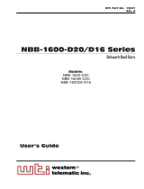
As shown in Figure 1, the RPB+ front panel includes a series of
LED indicators which function as follows:
À
POWER ON: Lights when AC Power is applied to the
RPB+.
Á
DATA INPUT: Flashes when ASCII commands are
received at the Control Port.
Â
PLUG ON (Plugs1-5): Lights when the corresponding
plug is switched On.

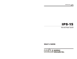
2.2. Back Panel
As shown in Figure 2, the RPB+ back panel includes the
following items:
À
Switched AC Outlets (Plugs1-5): For connection to up
to five AC devices. Each outlet is capable of switching up
to 15 Amps. The total for all five outlets must not exceed
15 Amps.
Á
SetUp Switches (RATE): A bank of four DIP Switches
which set the Control Port baud rate, select the Off Time
duration, enable/disable the Password Option, and
enable/disable the Read Only Mode.
Â
RS232 (Control) Port: For connection to an external
modem or local PC. The RPB+ accepts ASCII commands
via the Control Port.
Ã
DEFAULT Button: Reads Rate Switch settings and sets
parameters accordingly. This allows the user to change
Rate Switch settings without re-booting the RPB+ and
connected devices. The Default Button can also be used to
bypass the Password Prompt.
Ä
Power Cable (115 VAC Units)
Power Cable Receptacle (230 VAC Units)
Å
Circuit Breaker: 15 Amps
Æ
Power Switch

3. Installation
3.1. SetUp Switches
The SetUp Switches select the baud rate and Off Time, and
enable/disable the Password feature and Read Only Mode. If
switch settings are changed while the unit is powered On, press
the Default Button to re-read switches. The Default Button
allows the user to change switch settings while power is on,
without re-booting the RPB+ and connected devices.
Note: If Rate Switch settings are changed while the
unit is powered on, new parameters will not take
effect until the Default Button is pressed, or the
RPB+ is powered Off and On.
Off Time: When a boot cycle is initiated, the "Off Time"
determines the length of time the device will remain off until
power is restored.
Password: When enabled, a password is required in order to
access the RPB+ Command Mode (Default = [Enter]). To re-
define the Password, refer to Section 4.
Read Only Mode: When enabled, the /P command (Define
Parameters) is suppressed. This allows the user to invoke
On/Off/Boot commands, but prevents redefinition of
parameters such as the Password and Power-Up Default.
Switch Function Up Down
* = Factory Setting
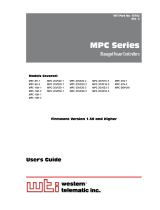
3.2. Control Port Connection
The male, DB9 connector (labeled "RS232") is used for
connection to an external modem or local PC. The RS232 Port
uses a DTE configuration, similar to an AT computer. Figure 3
describes the Control Port interface.

3.2.1. Connecting to a Modem
When connecting directly to an external modem, use a standard
AT to Modem cable. Make certain the modem is initialized at
the same baud rate as the RPB+ (SetUp Switch 1). The modem
must be placed in Auto-Answer mode, and set to answer in one
ring. Please refer to the user’s guide for your external modem in
order to determine the appropriate AT command string.
3.3. Power Connection
The Power Switch located on the back panel must be “On” in
order for the RPB+ to operate. Each time the unit is powered
On, the five AC outlets will be switched On or Off, as dictated
by the Power-Up Default String (see Section 4.1). Each outlet is
capable of switching up to 15 Amps of AC power. The total for
all 5 outlets cannot exceed 15 Amps.

4. Start-Up / Configuration
1. Access the RPB+ Command Mode: The RPB+ is
transparent to parity and will accept 7 or 8 bit characters,
but will always answer back at 8 bits, no parity. Make
certain your communications program (e.g. ProComm) is
set for the appropriate baud rate, bits, and parity. It is also
recommended to set the communications program for TTY
mode.
a) Via Modem: Start your communications program.
Dial the external modem connected to the RPB+. Wait
for the Connect message and proceed to Step 2.
b) Via Local PC: Start your communications program.
2. Password: If the Password function is enabled, the unit
will display a prompt. Key in the Password and press
[Enter]. If the password has not yet been defined, just
press [Enter].
Notes:
· The Password feature is case sensitive.
·
If you forget your password, press the Default
Button when the Password Prompt appears, then
invoke the /P command to display the Password.
3. The RPB+ will display the Status Screen (Figure 5).
4. When the "RPB+>" prompt appears, type /P [Enter] to
define system parameters. The unit will display a series of
prompts.
Notes:
·
RPB+ commands are not case sensitive.
·
To skip a prompt without changing its current
definition, press [Enter].
·
To exit from the Define Parameters function, press
[Esc] at any time. Parameters defined up to that
point will be saved.
a) Location: Key in a text string that describes the RPB+
location (up to 23 characters).

b) Password: To re-define the password (Default =
[Enter]), key in the new password (up to 8 characters)
and press [Enter]. The password can include blank
spaces and higher order ASCII characters. Note that
the Backspace key will not function during password
definition.
c) Default (Power-Up Default): Allows the user to
define default On/Off conditions for each switched
plug as described in Section 4.1. Key in the desired
Power-Up Defaults and press [Enter].
d) Echo Mode: When Echo Mode is enabled, commands
sent to the RPB+ will be echoed back to your PC or
terminal, allowing keyboard entries to be displayed by
your communications program. To enable or disable
the Echo Mode, type Y or N, press [Enter], then
continue with the parameter definition routine. When
the “RPB+>” prompt returns, type /D [Enter].
Notes:
·
The Echo Mode will not be enabled / disabled until
the /D command is invoked.
·
If the Default String includes invalid or missing
characters, the /D command will not function.
e) Plug Labels: Allows the user to identify the device
connected to each plug (e.g. "SERVER"). Key in the
desired name (up to 16 characters) and press [Enter].

4.1. The Power-Up Default String
The Power-Up Default String allows the user to select default
On/Off conditions for each switched AC outlet. When the RPB+
is powered up, or when the /D command (Set Defaults) is
invoked, each outlet will be set according to the Default String.
Note:
·
The Power-Up Default String includes five
characters; each character determines the default
On/Off condition for the corresponding plug. The
first character applies to Plug 1, the second
character applies to Plug 2, and etc..
·
To set a plug to default "ON" enter a one (1); to set
a plug to default "OFF", enter a zero (0).
·
If the Default String includes invalid or missing
characters, plugs will be switched “Off” when the
unit is powered up, regardless of the conditions
shown by the Status Screen. In addition, the /D
command will not function.
Example 1: To set default On/Off conditions as follows:
ON: Plugs 1 and 5
OFF: Plugs 2, 3, and 4
The Power-Up Default String would be defined as "10001".
Example 2: To set default plug conditions as follows:
ON: Plugs 3, 4, and 5
OFF: Plugs 1 and 2
The Power-Up Default String would be defined as "00111".

5. Operation
The device connected to the Control Port must send ASCII
characters at the same data rate as the RPB+. The unit accepts 8
bits no parity, or 7 bits even or odd parity, but will always
answer back at 8 bits, no parity.
Access the RPB+ Command Mode as described in Section 4,
Step 1. When the "RPB+>" prompt appears, the user may invoke
the following commands.
Notes:
·
Commands are not case sensitive.
·
Wait for the "RPB+>" prompt to appear before
entering commands. The prompt will not re-appear
until the previous command is complete.
·
If an invalid command or parameter is entered, the
RPB+ will respond with the "?" message.
1. Switch Plug(s) On: To power-on one or all of the five
switched plugs, type /n ON [Enter]. Where "n" is a plug
number from 1 to 5 and an asterisk (*) indicates the
command should be applied to all plugs.
2. Switch Plug(s) Off: To power-off one or all of the five
switched plugs, type /n OFF [Enter]. Where "n"isa
plug number from 1 to 5 and an asterisk (*) indicates the
command should be applied to all plugs. Note that "OFF"
can also be entered as "OF".
3. Boot Plug(s): To initiate a Boot cycle at one or all of the
switched plugs, type /n BOOT [Enter]. Where "n"isa
plug number from 1 to 5 and an asterisk (*) indicates the
command should be applied to all plugs. Note that
"BOOT" can also be entered as "B". The RPB+ will display
a series of periods (dots) while the Boot cycle is in
progress.
4. Status: To display the Status Screen, type /S [Enter].
5. Enter Parameters: To define parameters, such as the
Location I.D., Power-Up Default, and Plug Labels, type
/P [Enter] and refer to Section 4, Step 4.

6. Set Plugs to Default: To set all plugs to the Power-Up
Defaults, type /D [Enter]. Note that if the Default String
includes missing or invalid characters, the /D command
will not function.
7. Exit: To exit from command mode, type /X [Enter].
Note:
When the /n ON/OFF/BOOT command is invoked,
the port (n) must be specified by number. The Port
Label cannot be used to specify the desired port.
ON / OFF / BOOT Examples:
·
To Switch Plug 3 ON, type /3 ON [Enter].
·
To switch all plugs ON, type /* ON [Enter].
·
To switch plug 5 OFF, type /5 OFF [Enter].
·
To switch all plugs OFF, type /* OFF [Enter].
·
To initiate a boot cycle at Plug 2, type /2 BOOT [Enter].
·
To initiate a boot cycle at all plugs,
type /* BOOT [Enter].

Appendix A: Specifications
Switched Power Plugs: 5 code-selectable AC plugs rated 15 amps
max. Each. Total switched power for all plugs not to exceed 15
amps. Unit initially powers up to ON condition.
RS232 Port:
DB9 Connector: A 9 Pin Male connector wired in a DTE
configuration.
Pin Signal I/O
Coding: Asynchronous. 7-8 bits, any parity
Data Rate: 2400, 9600 bps (Switch Selectable)
LEDs: Power ON, Control Input, Plug On (5)
Temperature: 0°Cto30° C operating
Power:
115 VAC Model: Internal 115 VAC 60 Hz
(15 Amps Maximum Load).
230 VAC Model: Internal 230 VAC 60 Hz
(15 Amps Maximum Load).
Size: 1.75" x 17.00" x 6.5" (HxWxD).
Requires one rack space.
Mounting: 19" Rack Mount Bracket Included.
24" Rack Mount Bracket Optional.
Weight: 5 pounds shipping weight

Customer Service
Customer Service hours are from 8:00 AM to 5:00 PM, PST,
Monday through Friday. When calling, please be prepared to
give the name and make of the unit, its serial number and a
description of its symptoms. If the unit should need to be
returned for factory repair it must be accompanied by a Return
Authorization number from Customer Service.
WTI Customer Service
5 Sterling
Irvine, California 92618
949-586-9950
Toll Free: 1-800-854-7226
Fax: 949-583-9514
E-Mail: [email protected]
FCC Statement
This device complies with part 15 of the FCC rules. Operation is
subject to the following two conditions:
1. This device may not cause harmful interference, and
2. This device must accept any interference received,
including interference that may cause undesired operation.
Trademark and Copyright Information
WTI and Western Telematic are trademarks of Western Telematic
Incorporated. All other product names mentioned in this
publication are trademarks of their respective companies.
Information and descriptions contained herein are the property of
Western Telematic, Inc.. Such information and descriptions may
not be copied, disseminated or distributed without the express
written consent of Western Telematic, Incorporated.
©Copyright Western Telematic, Inc., 1998. All right reserved.
Printed in the United States of America.
October 1998
WTI Part Number: 12651 Rev. B


· ·
·
·
/