Page is loading ...

Model 8552/8554
Q-TRAKTM Plus
IAQ Monitor
TRAKPROTM Data Analysis Software enclosed
Operation and Service Manual
1980417, Revision I
June 2006
Indoor Air Quality


June 2006
P/N 1980417, Rev I
SHIP/MAIL TO:
TSI Incorporated
500 Cardigan Road
Shoreview, MN 55126-3996
USA
U.S.
Customer Service:
(800) 874-2811/(651) 490-2811
Fax:
(651) 490-3824
E-mail address:
Website:
http://www.tsi.com
INTERNATIONAL
Customer Service:
(001 651) 490-2811
Fax:
(001 651) 490-3824
Model 8552/8554
Q-TRAKTM Plus
IAQ Monitor
Operation and Service
Manual

ii
Copyright ©
TSI Incorporated / 2000–2006 / All rights reserved.
Address
TSI Incorporated / 500 Cardigan Road / Shoreview, MN 55126 / USA
Fax No.
(651) 490-3824
Limitation of Warranty and Liability (effective July 2000)
Seller warrants the goods sold hereunder, under normal use and service as described in the
operator's manual, shall be free from defects in workmanship and material for twenty-four (24)
months, or the length of time specified in the operator's manual, from the date of shipment to the
customer. This warranty period is inclusive of any statutory warranty. This limited warranty is
subject to the following exclusions:
a. Hot-wire or hot-film sensors used with research anemometers, and certain other components
when indicated in specifications, are warranted for 90 days from the date of shipment.
b. Parts repaired or replaced as a result of repair services are warranted to be free from defects
in workmanship and material, under normal use, for 90 days from the date of shipment.
c. Seller does not provide any warranty on finished goods manufactured by others or on any
fuses, batteries or other consumable materials. Only the original manufacturer's warranty
applies.
d. Unless specifically authorized in a separate writing by Seller, Seller makes no warranty with
respect to, and shall have no liability in connection with, goods which are incorporated into
other products or equipment, or which are modified by any person other than Seller.
The foregoing is IN LIEU OF all other warranties and is subject to the LIMITATIONS stated
herein. NO OTHER EXPRESS OR IMPLIED WARRANTY OF FITNESS FOR
PARTICULAR PURPOSE OR MERCHANTABILITY IS MADE.
TO THE EXTENT PERMITTED BY LAW, THE EXCLUSIVE REMEDY OF THE USER OR
BUYER, AND THE LIMIT OF SELLER'S LIABILITY FOR ANY AND ALL LOSSES,
INJURIES, OR DAMAGES CONCERNING THE GOODS (INCLUDING CLAIMS BASED
ON CONTRACT, NEGLIGENCE, TORT, STRICT LIABILITY OR OTHERWISE) SHALL
BE THE RETURN OF GOODS TO SELLER AND THE REFUND OF THE PURCHASE
PRICE, OR, AT THE OPTION OF SELLER, THE REPAIR OR REPLACEMENT OF THE
GOODS. IN NO EVENT SHALL SELLER BE LIABLE FOR ANY SPECIAL,
CONSEQUENTIAL OR INCIDENTAL DAMAGES. SELLER SHALL NOT BE
RESPONSIBLE FOR INSTALLATION, DISMANTLING OR REINSTALLATION COSTS
OR CHARGES. No Action, regardless of form, may be brought against Seller more than 12
months after a cause of action has accrued. The goods returned under warranty to Seller's
factory shall be at Buyer's risk of loss, and will be returned, if at all, at Seller's risk of loss.
Buyer and all users are deemed to have accepted this LIMITATION OF WARRANTY AND
LIABILITY, which contains the complete and exclusive limited warranty of Seller. This
LIMITATION OF WARRANTY AND LIABILITY may not be amended, modified or its terms
waived, except by writing signed by an Officer of Seller.
Service Policy
Knowing that inoperative or defective instruments are as detrimental to TSI as they are to our
customers, our service policy is designed to give prompt attention to any problems. If any
malfunction is discovered, please contact your nearest sales office or representative, or call TSI's
Customer Service department at (800) 874-2811 (USA) or (001 651) 490-2811 (International).

iii
CONTENTS
1. UNPACKING AND PARTS IDENTIFICATION..................................1
Unpacking the Q-TRAKTM Plus IAQ Monitor..........................................1
Optional Accessories ...............................................................................3
2. SETTING UP...........................................................................................5
Supplying Power to the Q-TRAKTM Plus IAQ Monitor............................5
Installing the Batteries..........................................................................5
Using the AC Adapter..........................................................................5
Instrument Software and Communications Setup....................................5
Setting up TRAKPROTM Data Analysis Software..................................6
Connecting the Q-TRAK Plus IAQ Monitor to the Computer ..............6
Setting up the Communications Port....................................................6
Using the Optional Instrument Stand.......................................................7
Using the Optional Probe Stand...............................................................7
Connecting the Optional Portable Printer................................................8
3. OPERATION...........................................................................................9
Overview..................................................................................................9
Q-TRAK Plus IAQ Monitor Keypad.........................................................9
Turning the Instrument On.......................................................................9
Survey Mode..........................................................................................10
Units.......................................................................................................11
Sample Mode.........................................................................................11
Recording and Saving a Single Data Point ........................................12
Printing Saved Single Data Points ................................................12
Main Menu.............................................................................................12
Time Constant....................................................................................13
Log Mode...........................................................................................13
Log Mode: Display of Real-Time Data........................................13
Log Mode 1: Log Interval............................................................14
Log Mode 2 and 3.........................................................................16
Programming Log Mode 2 or 3 Using TRAKPRO Data
Analysis Software......................................................................16
Sample Protocol for Log Mode 2 or 3 ..........................................19
Memory Considerations................................................................22
Auxiliary Sensor ...........................................................................22
Keypad Lockout Switch................................................................23
Setup Menu ........................................................................................24
Time/Date......................................................................................24
Backlight.......................................................................................26
Clear Memory...............................................................................27
Calibration.....................................................................................28
Printer............................................................................................28

iv
Ventilation Rates................................................................................28
% Outside Air...............................................................................29
Statistics.............................................................................................31
Single Point Statistics ...................................................................31
Logged Test Statistics...................................................................31
4. CALIBRATION AND MAINTENANCE ............................................33
Calibrating the CO2 Sensor....................................................................33
Calibrating the CO Sensor.....................................................................37
Calibrating the Temperature or Relative Humidity Measurement.........41
Restore Factory Calibration...................................................................42
Storage Precautions ...............................................................................43
5. AUXILIARY SENSORS ......................................................................45
Model 8590 Auxiliary Temperature Sensor Accessory.........................45
Model 8592 Air Velocity Probe (AVP) Accessory...............................46
Basic Applications.............................................................................46
Upgrading Your Q-TRAKTM Plus IAQ Monitor and
TRAKPROTM Data Analysis Software .............................................47
Using the Telescoping Probe.............................................................49
Measuring Air Velocity .....................................................................49
Measuring Air Flow Rate or Average Velocity.................................50
Q-TRAK Plus LCD Display During AVP Operation..........................51
Measuring Average Velocity.............................................................52
Measuring Volumetric Flow Rate......................................................53
Maintenance.......................................................................................57
Calibration .........................................................................................57
Special Display Messages..................................................................57
Storage...............................................................................................57
6. TROUBLESHOOTING ........................................................................59
A. SPECIFICATIONS ...............................................................................61
B. STANDARD VELOCITY VS. ACTUAL VELOCITY
MEASUREMENTS...............................................................................65
To obtain any of the listed Application Notes, contact TSI at:
U.S. (800) 874-2811/(651) 490-2811, Fax: (651) 490-3824
International (001 651) 490-2811, Fax: (001 651) 490-3824
These Application Notes can also be found under TSI’s web site:
http://www.tsi.com.

1
Chapter 1
Unpacking and Parts Identification
Unpacking the Q-TRAKTM Plus IAQ Monitor
Carefully unpack the Q-TRAKTM Plus IAQ Monitor from the shipping
container. Use the tables and illustrations below to make certain that there
are no missing components. Contact TSI immediately if anything is missing
or damaged.
Figure 1-1: Models 8552/8554 Q-TRAK Plus IAQ Monitor
with Calibration Collar and Batteries
Ref Qty Item Description Part/Model
1 1 Q-TRAK Plus IAQ Monitor 8552 or
8554
2 1 Calibration Collar 801679
3 4 Batteries (AA alkaline) N/A
4 1 Computer Interface Cable (RS-232) 800563
5 1 AC Adapter
115 V, NEMA-5
230 V, Eur., CEE 7/16
230 V, Great Britain
240 V, Australian
2613033
2613078
800169
2613105
6 1 Probe Stand (not shown) 800679
12
3
45

Chapter 1
2
Figure 1-2: Calibration Certificate, Operation and
Service Manual, TRAKPROTM Data Analysis Software
Ref Qty. Item Description Part/Model
1 1 Calibration Certificate N/A
2 1 Operation and Service Manual 1980417
3 1 TRAKPROTM Data Analysis Software N/A
2
3
1

Unpacking and Parts Identification 3
Optional Accessories
The following pages contain component identification information for
optional accessories available for the Q-TRAKTM Plus IAQ Monitor.
Figure 1-3: Auxiliary Sensor, Probe Stand, Air Velocity Probe
Ref Item Description Part/Model
1 Probe Stand 800679
2 Auxiliary Temperature Sensor 8590
3 Air Velocity Probe 8592
1
2
3

Chapter 1
4
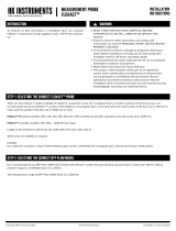
Figure 1-4: Portable Printer Kit
Qty Item Description Part/Model
1 Portable printer 8930

5
Chapter 2
Setting Up
Supplying Power to the Q-TRAKTM Plus IAQ Monitor
The Model 8552/8554 Q-TRAKTM Plus IAQ Monitor may be powered with
four AA alkaline batteries or the optional AC adapter.
Installing the Batteries
Insert four AA-size batteries, as indicated by the diagram located on the
inside of the battery compartment. TSI ships the Q-TRAK Plus monitor
with alkaline batteries. Rechargeable batteries may also be used (battery
charger and batteries are not included and are not available from TSI).
Using the AC Adapter
The AC adapter allows you to power the Q-TRAK Plus monitor from an
AC wall outlet. When using the AC adapter, the batteries (if installed)
will be bypassed. The AC adapter is not a battery charger and will not
charge rechargeable batteries.
The Q-TRAK Plus monitor has an internal, non-user accessible battery
that is used to keep memory intact when power is turned off. Changing
the AA-size batteries or disconnecting the AC adapter will not cause
data to be lost. This battery is designed to last for years. TSI will install
a new battery, if necessary, when the unit is returned to the factory for
service.
Caution
! The use of an improper AC adapter will cause severe damage
to the instrument.
Instrument Software and Communications Setup
The Q-TRAK Plus IAQ Monitor comes with special software called
TRAKPROTM Data Analysis Software, which is designed to provide you with
maximum flexibility and power when using the Q-TRAK Plus monitor. The
following sections describe how to install the software and set up the
computer.

Chapter 2
6
Setting up TRAKPROTM Data Analysis Software
Follow the instructions on the label of the TRAKPRO software to install
the software on your computer. TRAKPRO software contains a very
comprehensive Help Function. This utility provides all the necessary
information to guide you in all aspects of software operation. The
software is shipped on a CD-ROM. It is available on diskette format,
upon special request. Updates are available from the TSI website.
Connecting the Q-TRAK Plus IAQ Monitor to the Computer
Each Q-TRAK Plus monitor comes equipped with an RS-232, 9-pin
serial cable. One end of the cable is a 9-pin D subminiature connector
labeled COMPUTER; the other end is an RJ-45 modular connector that
connects with the Q-TRAK Plus communications port. Serial port
connectors always have pins (male) on the computer side.
1. Locate an available RS-232 serial port on your computer: for
example, COM1 or COM2.
2. Connect the RS-232 cable to the available serial port on your
computer.
3. Connect the RJ-45 connector to the Q-TRAK Plus monitor
communications port.
Setting up the Communications Port
To communicate with the Q-TRAK Plus monitor, the software must be
configured for the proper COM port. The TRAKPRO software can be
manually set to operate on a specific COM port, or it can automatically
find a Q-TRAK Plus monitor that is attached to any COM port. To set up
the COM port, do the following:
1. Turn on the Q-TRAK Plus monitor.
2. Start the TRAKPRO software.
3. Select Instrument Setup, Communications in the TRAKPRO
software. The following dialog is displayed:

Setting Up 7
Figure 2-1: Instrument Setup, Communications Dialog Box
4. Select the correct serial port (such as, COM2); then select Test. The
software will verify that you have set up the communications port
correctly and that it is communicating with the Q-TRAK Plus
monitor. The system displays an information message indicating
whether it was able to establish communications.
5. As an alternative, select Find Port, to have the monitor search the
available COM ports, looking for an attached Q-TRAK Plus
monitor.
6. Select OK to accept the setup, or Cancel to discard the changes.
Using the Optional Instrument Stand
The Q-TRAK Plus IAQ Monitor can be used with an instrument stand
(available as an accessory). When placed on a level surface, the instrument
stand is designed to hold the instrument and the probe at a convenient
viewing angle. The instrument stand may also be used to hang the monitor
on a wall.
To use the stand, simply detach the battery door from the monitor and
replace it with the instrument stand (see Figure 2-2).
Using the Optional Probe Stand
A separate probe stand is available as an accessory. Use the bracket that is
located on the probe and slide it on the probe stand as shown in Figure 2-2.

Chapter 2
8
Figure 2-2: Optional Probe and Instrument Stands
Connecting the Optional Portable Printer
To connect the portable printer to the Q-TRAK Plus monitor, do the
following:
1. Ensure that the Q-TRAK Plus monitor and printer are off.
2. Locate the printer interface cable and connect the 9-pin end labeled
PRINTER to the printer and the other end to the communications port
on the Q-TRAK Plus monitor.
3. Turn on the Q-TRAK Plus monitor; then turn on the printer.
Note: Always turn on the Q-TRAK Plus monitor before turning on the
printer. If the printer prints question marks (??????), asterisks
(******), or random characters, reset it by turning it off and
then on again. If necessary, refer to the Portable Printer
Manual.

9
Chapter 3
Operation
Overview
The Model 8552/8554 Q-TRAKTM Plus IAQ Monitor measures CO2,
temperature, relative humidity, calculates dew point, wet bulb, and %
outside air, and measures one (1) additional parameter. The Model 8554 will
also measure CO. The instruments have three main modes of operation:
Survey, Sample, and Data Log.
Survey mode: When the Q-TRAK Plus monitor is first turned on, it will
be in the Survey mode. This mode is used to display the real-time
readings of the sensors. The instrument will update the displayed
readings once each second.
Sample mode: The Sample mode is used to capture a 10-second,
averaged reading of all the parameters. These “single sample points”
may be stored in memory and can be displayed later, or downloaded to a
computer using the TRAKPRO software.
Data Log mode: The Data Log mode is used to record readings over a
period of time, and store these readings in the instrument memory. Data
files may be downloaded to a computer for later analysis using the
TRAKPRO software. Q-TRAK Plus has three different data log modes.
Q-TRAK Plus IAQ Monitor Keypad
The Model 8552/8554 Q-TRAK Plus IAQ Monitor is controlled through a
series of menus that are navigated using the arrow keys (S,T,W, X) (see
Figure 3-1). The Enter key () is used to select the desired option, while the
Escape key ( ) is used to go back to the previous menu. Each screen
contains prompting words and symbols. When pressing the keys on the front
panel, the monitor beeps to confirm each key press. The key allows access
to the Main Menu from the Survey mode.
Turning the Instrument On
Use the ON/OFF key to turn the Q-TRAK Plus monitor on and off. The
instrument's power-up sequence consists of a startup screen that displays the
instrument’s model number, serial number, firmware version, available
memory, date and current time. The display will also show various status
messages. The startup sequence lasts for 20 seconds before entering Survey
mode. A reminder may appear when the instrument is due for servicing.

Chapter 3
10
Figure 3-1: Q-TRAK Plus IAQ Monitor Keypad and Display
Survey Mode
After the instrument has completed its power-up sequence, the Q-TRAK Plus
monitor will automatically go into the Survey mode.
Note: It is not unusual for gas sensors to take some time to become
stable. If readings appear unusual at start-up, please allow
about one-half minute for the sensors to stabilize.
In the Survey mode, the Q-TRAK Plus monitor displays all parameters
simultaneously. The values are updated once per second. You may select
any of the parameters to be shown in large font at the top of the display. This
is called the primary parameter. Select the primary parameter by using the S
or T keys to highlight the parameter of interest, then press the key to
display that parameter in large font at the top of the screen. In addition, the
units of some parameters may also be changed. For example, temperature
may be shown in either °F or °C. To adjust the units, scroll to the desired
parameter using the S or T keys, then adjust the units using the W or Xkey
(refer to the units section in this chapter, see Figure 3-2).
Enter key
Arrow keys
Escape key
Power on/off key

Operation 11
Figure 3-2: Survey Mode Screen (sample)
Ref Description
1 Primary Parameter (CO2 concentration is shown).
2 Sample mode. Used for capturing single data points.
3 Remaining parameters.
4 Status message area.
5 Battery status.
Units
To change units displayed in the Survey mode use the S or T key to select
the parameter. Press either the W or Xkey and the units of the selected
parameter will change accordingly. The units displayed on the instrument
will be the same units that are stored during the log mode.
Sample Mode
The Sample mode is the default selection in the Survey Mode (the reverse
highlight indicates that it is selected). The Sample mode is used to capture a
single, 10-second averaged data point of all measured parameters.
1
2
4
3
805
2.0 PPM CO
75.1 °F TEMP
35.1 % RH
70.1 °F TEMP 2
PPM
CO2
SAMPLE
5

Chapter 3
12
Recording and Saving a Single Data Point
With SAMPLE selected and the key pressed, the Q-TRAK Plus
monitor begins a countdown. During these 10 seconds, it is taking an
average reading of each parameter. At the end of the averaging period,
the following sample screen is displayed:
SAMPLE # 1
75.1 °F TEMP 2
805 PPM CO2
2.0 PPM CO
75.1 °F TEMP
35.1 % RH
SAVE SAMPLE? YES NO
Figure 3-3: Record Single Data Point
The YES selection is highlighted by default. If you press the ↵ key, the
single data point will be stored in memory. Press the X key to highlight
NO to discard the data point.
Note that the first sample is given the name/number “Sample 1.” The
sample number will automatically increment for each subsequent
sample.
Printing Saved Single Data Points
A hardcopy of the results of the saved test sample can be generated
if the portable printer is attached to the Q-TRAK Plus monitor and
the Printer Output feature is enabled.
Main Menu
The Main Menu can be accessed through the SURVEY MODE by pressing
the key. The Main Menu Mode is the highest level in the menu structure.
It provides a central point where you can select alternate modes of operation.
-MAIN MENU-
TIME CONSTANT
LOG MODE 1
SETUP
VENTILATION RATES
STATISTICS
Figure 3-4: Main Menu

Operation 13
Time Constant
Highlighting and selecting TIME CONSTANT displays the Time
Constant Menu. This allows you to adjust the dampening time-constant
that will affect the real-time display of parameters, in the Survey mode
only. The values shown in the Survey Mode are updated once per
second; however, the readings shown are averaged over the time-
constant period.
Log Mode
To select a Log Mode, scroll to LOG MODE 1 using the S or T key.
Adjust the mode using theW or X key to select LOG MODE 1, 2, or 3.
Press the key to start logging data. Log Mode 1 is programmed and
initiated by the keypad. Log Mode 2 and Log Mode 3 are programmed
using the TRAKPRO software. Log Mode will only record data that is
visible on the display.
Log Mode: Display of Real-Time Data
To begin a data logging session, select a log mode from the Main
Menu and press the ↵ key. The Q-TRAK Plus monitor will begin
recording logged data into the instrument memory and display the
real-time values (see Figure 3-5).
LOG MODE 1 TEST 1
75.1 °F TEMP 2
805 PPM CO2
0.0 PPM CO
75.1 °F TEMP
35.1 % RH
NEXTWX ↵ TO STOP
Figure 3-5: Log Mode: Statistical Data
Ref Description
1 The Q-TRAK Plus monitor is in Log Mode 1.
2 The Test ID number is 1. This number is automatically incremented
for each new test.
3 The real-time values for each parameter are displayed.
4 Use the W or X key to view the statistics for the current test.
5 Pressing the key will terminate the current test.
3
1
4 5
2

Chapter 3
14
While logging, you are able to view statistical summary data of the
current test. Pressing the W or Xkey will display the statistics for
each parameter. The CO2 summary screen is shown in Figure 3-6.
TEST 1
820 PPM CO2
MIN: 800 PPM CO2
06:51 02/04/05
MAX: 950 PPM CO2
10:20 02/04/05
NEXTWX ↵ TO STOP
Figure 3-6: Log Mode: CO2 Summary Screen
Ref Description
1 Test ID
2 Current CO2 reading.
3 Minimum CO2 reading during the test.
4 Time and date at which the minimum CO2 reading occurred.
5 Maximum CO2 reading, with time and date.
Log Mode 1: Log Interval
The log interval is both a frequency and an averaging period. For
example, when the log interval is set to 5 minutes, readings will be
recorded at 5-minute intervals. Each reading will be the average
value measured over that 5-minute interval.
The Select Log Interval menu allows you to view the current
logging interval used during LOG MODE 1 (see “Log Mode 2 and
3” section, later in this chapter, for more information about data
logging). The menu screen is shown below in Figure 3-7.
-SELECT LOG INTERVAL-
LOG INTERVAL 00:01
MM:SS
↵ TO ACCEPT LOG
INTERVAL AND BEGIN
LOGGING
Figure 3-7: Log Mode 1: Select Log Interval
3 4
5
2
1
/