IDEC HS5D Series Operating instructions

Type
Operating instructions

IDEC HS5D Series Safety Switches are a reliable choice for monitoring the position of movable guards and interlocking devices. They feature a unique head removal detection function that opens the NC contact of the main circuit when the head is removed, while keeping the other NC contacts closed. This allows for easy maintenance and troubleshooting. The switches are also highly durable, with a mechanical durability of 1,000,000 operations and an electrical durability of 100,000 operations.

IDEC HS5D Series Safety Switches are a reliable choice for monitoring the position of movable guards and interlocking devices. They feature a unique head removal detection function that opens the NC contact of the main circuit when the head is removed, while keeping the other NC contacts closed. This allows for easy maintenance and troubleshooting. The switches are also highly durable, with a mechanical durability of 1,000,000 operations and an electrical durability of 100,000 operations.

B-1902-1(0)
INSTRUCTION SHEET - HS5D Series Safety Switch
( 1 / 5 )
2016.08
1Type
HS5D-11ZRNM
Contact configration
11 : 1NO-1NC
02 : 2NC
12 : 1NO-2NC
03 : 3NC
Gland Port Size
Blank : G1 /2
M : M20
P : PG13.5
Material of Head
Blank : Plastic
Z : Metal
Ratings approved by safety agencies
(1) TÜV rating / CCC rating / KOSHA rating
AC-15 250V, 3A
DC-13 30V, 4A
(2)UL, c-UL rating
A300 3A, 250V ac, Pilot Duty
4A, 30V dc
EN ISO / ISO14119
IEC60947-5-1, EN60947-5-1, GS-ET-15
UL508, CSA C22.2 No.14, GB14048.5
IEC60204-1, EN60204-1
Low Voltage Directive, Machinery Directive
10A
900 operations / hour
0.05 to 1.0 m/s
10 mm minimum (HS9Z-A51)
50 N minimum (HS9Z-A51)
50mΩ maximum (Initial value)
IP67 (IEC60529)
250V AC, 10A fast acting type fuse
30V
10A
10A
8A
4A
125V
10A
5A
2.2A
1.1A
250V
6A
3A
1.1A
0.6A
Resistive load (AC12)
Induc ive load (AC15)
Resistive load (DC12)
Induc ive load (DC13)
Applicable Standards
Standards for Use
Applicable Directives
Thermal Current ‹Ith›
Contact Ra ings
‹Ue, Ie›
Operating Frequency
Operating Speed
Direct Opening Travel
Direct Opening Force
Contact Resistance
Degree of Protection
Short-Circuit Protective Device
AC
DC
Operating Condition Operating Temperature
Operating Humidity
Pullution Degree
-30 to +70°C (no freezing)
45 to 85%RH (no condensation)
3 (Inside 2)
Al itude 2000m maximum
Impulse with voltage ‹Uimp› 4kV
Rated Insula ion voltage ‹Ui› 300V
Mechanical Durability
1,000,000 operations minimum (GS-ET-15)
B10d
Electrical Durability
Conditional short circuit current
2,000,000 (EN ISO 13849-1 Annex C Table C.1)
100A(250V)
100,000 operations min. (AC-12 250V•6A)
1,000,000 operations min. (AC/DC 24V 100mA)
(900 operations / hour)
HS5D
Safety Switch
HS9Z-SH5
Actuator
Hinged
Door
HS9Z-A52
Actuator
Door Stop
HS5D
Safety Switch
Door
HS9Z-A51
Actuator
(Examples of Mounting on Sliding Doors)
(Examples of Mounting on Hinged Doors)
2Specifications and Ratings
3Mounting Examples
Class of Protection Class II (IEC61140)
Confirm that the delivered product is what you have ordered.
Read his instruction sheet to make sure of correct operation.
In this operation instruction sheet, safety precautions are categorized in order of
importance to Warning and Caution :
Warning notices are used to emphasize that improper operation may cause severe
personal injury or death.
Caution notices are used where inattention might cause personal injury or damage to
equipment.
INSTRUCTION SHEET
Original Instructions
Safety Switch
HS5D Series
SAFETY PRECAUTIONS
CAUTION
WARNING
* In order to verify if the product
you are interested in is certified
with the S mark, please check
the following section on our
website: "List of type numbers
certified with the S mark"
Install the interlock switch on the immovable machine or guard, and install the
actuator on the movable door. Do not install both interlock switch and actuator on
the movable door, otherwise the angle of insertion of the actuator to the safety switch
may become inappropriate, and failure will occur.
Changing the Mounting Directions of
the HS5D Head
The head of HS5D can be mounted in four
directions by removing the four screws on
the corners of the HS5D head.
WARNING
Mounting Directions of the HS5D Head
When replacing the HS5D head, make sure that no foreign object enters into the
safety switch.
Tighten the screws tightly, o herwise he safety switch may malfunction.
Don't remove the screws of head expect when the mouting directions of head is
changed.
• When tightening the screw in the head section with an electric screwdriver or
similar tool, temporarily tighten the first part of the screw by hand first, and then
tighten with the electric screwdriver.
Mounting the HS5D Head
Do not use the metal head for the HS5L with lock type. Be sure to use the plastic
head or metal head for the HS5D. Be sure to use the correct head.
When
Shipped Alternative Moun ing
Directions
Color:
Red
HS5D
Metal HeadPlastic Head Metal Head
HS5L
Metal,
Color:Silver
Metal,
Color:Silver
Plastic,
Color Red
Color:Black
Shock Resistance
Vibration Resistance
Damage Limits: 1000m/s2
Operating Extremes:10 to 55 Hz, half amplitude 0.5mm
Damage Limits: 30 Hz, half amplitude 1.5mm
10 operations min.
100MΩ(Initial value)
1,000V 1minute(Initial value)
Mechanical durability
Insulation resistance
Dielectric strength
HS5D Head Removal Detection Function (Screw Terminal No.11-12)
Interlocking device Type
/ the level of coded Type 2 Interlocking device
/ low level coded actuator (EN ISO / ISO14119)
B-1902-1(0)
INSTRUCTION SHEET - HS5D Series Safety Switch
( 2 / 5 )
2016.08
When the center of the hinged door is
on the extension line of
the actuator mounting surfade.
When the center of the hinged door is
on the extension line of the contact
surface of actuator and safety switch.
HS9Z-A52
HS9Z-A52A Mounting centers:12mm
Mounting centers:20mm
HS9Z-A55
R1
230 mm
230 mm
310 mm
70 mm
(Horizontal Swing)
R2
260 mm
260 mm
70 mm
(Vertical Swing)
R3
170 mm
120 mm
170 mm
50 mm
(Horizontal Swing)
R4
190 mm
140 mm
50 mm
(Vertical Swing)
Minimum Radius
(Actuator deviation) (Door movement)
≤ 1.7 mm
≤ 3.0 mm
≤ 2.5 mm
HS9Z-A51
HS9Z-A52
HS9Z-A51A
HS9Z-A52A
HS9Z-A55
Minimum Radius of Hinged Door
When using the safety switch for a hinged door, the minimum radius of the applica-
ble door is shown in the following figures.
Actuator Mounting Tolerance
Mounting tolerance of the actuator is 1.0mm in the four lateral directions.
Make sure he actuator can be inserted into the entry slot without any issue.
When closing the door, the actuator is inserted within a certain distance from the
reference position. The contact operation is not affected by the actuator movement.
The above example are based on the condi ion that the actuator enters and exits
the actuator entry slot smoothly when the door is closed or opened.
Since there may be deviation or dislocation of the hinged door, make sure of
correct operation in the actual application before installation.
CAUTION
Door Hinge Door Hinge Door Hinge Door Hinge
Minimum Radius
Minimum Radius
Minimum Radius
Minimum Radius
R1
R2
R4
R3
Actuator Stop
Safety Switch
Door Stop
HS9Z-A51
Actuator
Actuator Stop
Safety Switch Door Stop Safety Switch
HS9Z-A52
Actuator
HS9Z-A55
Actuator
Actuator Cover
Actuator Stop
Center Safety Switch
1.7mm 3.0mm
±1.0mm ±1.0mm HS9Z-A51 HS9Z-A52
HS5D Head Removal Detection Function
The the NC contacts of the two main circuits (11-12, 21-22) are operated similarly by
the actuator. But, when the HS5D head is removed, the NC contact of the main
circuit (11-12) is opened, and other NC contact (21-22) remains closed.
:Contact Closed :Contact Open
Main Circuit: 1211
21 22
Main Circuit:
Main Circuit (11-12)
Main Circuit (21-22)
Monitor Circuit (33-34)
Actuator inserted When the HS5D
head is removed
Actuator pulled
(31-32)
When the HS5D head is removed, the NC contact of the main circuit (11-12) is
opened, and other NC contact(s) remain closed. Use the NC contact of the main
circuit (11-12) for the safety circuit.
Turn off he power when using this function.
CAUTION
HS9Z-A51A/HS9Z-A52A
When there is a displacement of safety switch and actuateor, the actuator may hit the
entry slot of safety switch hardly, thus damaging the entry slot and acutuator. The
rubber cushions on the HS9Z actuator prevent the actuator from damaging the entry
slit by absorbing the shock with movement flexibility. Do not, however, exert exces-
sive shocks, otherwise the failure of safety switch may be caused.
The rubber cushions may deteriorate depending on the operating enviroment and
conditions. Immediately replace the deformed or cracked rubber cushions with new
ones.
*1 When the torque is not enough to recommended
screw tightening torque, make sure hat the
screw do not become loose by using adhesive
sealants etc. to keep right operation and
mounting positioning.
*2 In the case of HS9Z-A51A and HS9Z-A52A,
using two M4 screws and two attached washers,
fasten the actuator securely on the door.
CAUTION
Recommended Screw Tightening Torque
Screw Tightening
Torque
1.8 to 2.2N m
0.2 to 0.4 N m
0.6 to 0.8 N m
2.7 to 3.3 N m
0.9 to 1.1 N m
For moun ing the safety switch
(M4 screw) *1
1.8 to 2.2 N m
0.8 to 1.2 N m
1.0 to 1.5 N m
For moun ing the actuator
(HS9Z-A51: M4 screw) *1
(HS9Z-A52: M4 Phillips screw)
*1, 2
(HS9Z-A51A/A52A/A55: two M4 screws)
For moun ing the HS5D lid (M3)
Terminal screw (M3)
Cable gland
For moun ing the HS5D head (M3)
Name or Use
M4 Screw
Washer
Rubber Cushion
Door
M4 mounting hole
Adjusting the Angle Adjustable (vertical/horizontal) Actuator
(Type HS9Z-A53/A55)
Using the angle adjustment screw (M3 hexagon socket set screw), the actuator angle
can be adjusted up to 20°(refer to dimensions).
The larger the actuator angle, the smaller the applicable radius of the door swing.
After installing the actuator, open the door. Then adjust the actuator angle so that the
actuator enters the entry slot of the safety switch properly.
After adjusting the actuator angle, apply loctite or the like on the adjustment screw to
prevent loosening.
(Type HS9Z-A53)
Tightening torque of angle adjustment screw : 0.8 N•m.
(Type HS9Z-A55)
Use screw locking agent that is compatible with the base material.
Base : PA66 (66 nylon) of glass reinforced grade
Angle adjustment screws : stainless steel
Actuator Mounting Reference Position
As shown below, the mounting reference position of the actuator inserted into the
safety switch is:
(Type HS9Z-A53)
The actuator stop film placed on the actuator touches the safety switch lightly.
(Except Type HS9Z-A53)
The actuator and actuator cover touches the actuator stop placed on the safety
switch lightly.
(After mounting the actuator, remove the actuator stop from the safety switch.)
B-1902-1(0)
INSTRUCTION SHEET - HS5D Series Safety Switch
( 3 / 5 )
2016.08
4Precautions for Operation
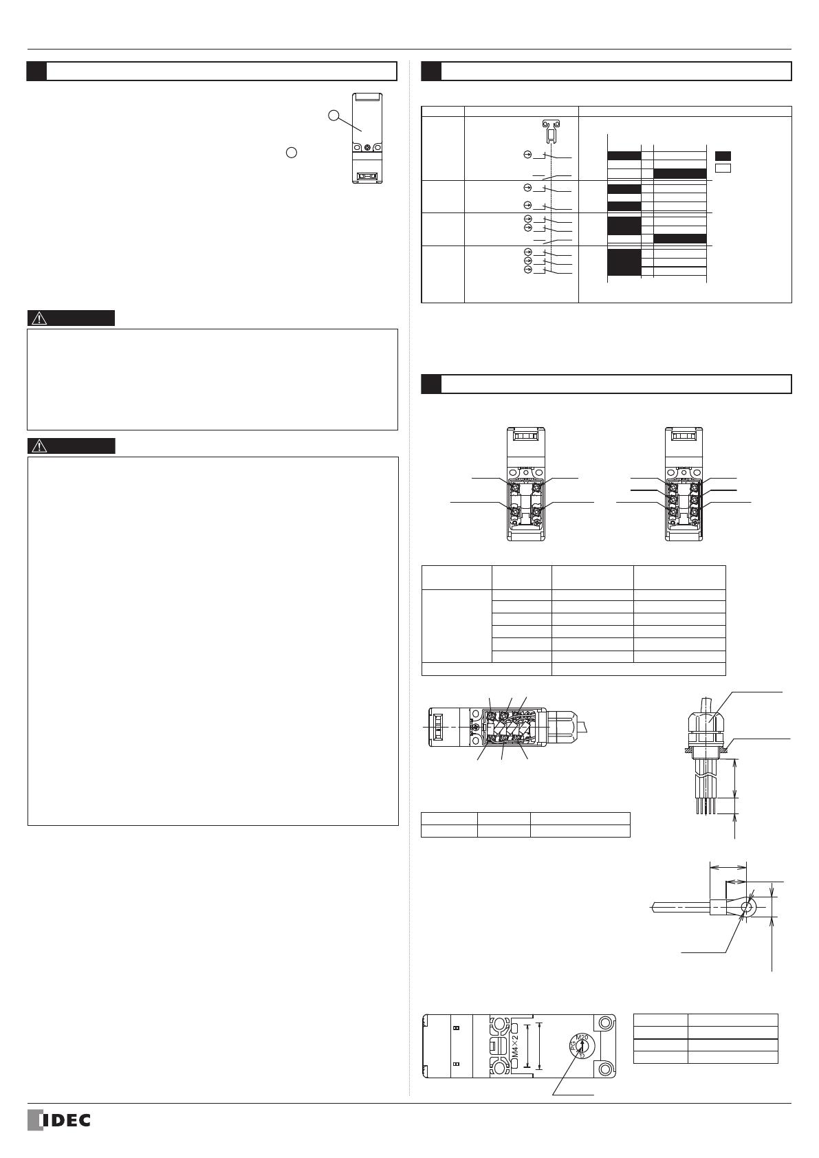
Wire Length inside the Safety Switch
F
E
D
C
B
A
Screw
Terminal No.
50±2
50±2
40±2
40±2
25±2
25±2
55±2
55±2
45±2
45±2
30±2
30±2
Wire Length:
L1 (mm)
Wire Stripping Length:L2(mm)
7±1
When using
crimping terminal When using without
crimping terminal
Recommended Wire Core Size: 0.5 to 1.5 mm2
Gland Port Size Identification
Gland port size is identified by the arrow on the back of the HS5D safety switch. The
following example shows he identification of the M20 gland port size.
Mark
G
PG
M20
Gland port size
G1/2
PG13.5
M20
Applicable Crimping Terminal
Manufacture Type
Recommended Wire Core Size
N0.5-3 0 2 to 0.5mm2
JST
Use an insulation tube on the crimping terminal.
• When using crimping terminals, be sure to install
insulation tubes on the crimping terminals to
prevent electric shocks.
No.31(33) No.32(34)
No.22
No.21
No.11 No.12
No.12
No.22(24)No.21(23)
No.11
E C A
BDF
L1L2
Safety Switch
Cable Gland
6.4mm max.
17.4mmmax.
4.2 to
5.8mm
Φ3.2mm
Arrow
22
20
Do not apply an excessive shock to the safety switch when open-
ing or closing the door. A shock to the safety switch exceeding
1000 m/s2 may cause failure.
Provide a door guide, and ensure that force is applied on the
safety switch only in the actuator insertion direction.
• When opening the safety switch lid to wire, open the lid 1 only.
(See the figure on the right.) Never remove other screws, other-
wise the safety switch may be damaged.
Entry of foreign objects in the actuator entry slot may affect the
mechanism of the switch and cause a breakdown. If the operating
atmosphere is contaminated, use a protective cover to prevent the entry of foreign
objects into he switch through the actuator entry slots.
When wiring or installing a gland, make sure that no foreign objects, dust, and water
enter into the safety switch.
Make sure to install the product in a place where it cannot be damaged. Make sure
to conduct a proper risk assessment evaluation before using the product, and use a
shield or a cover to protect the product if need be.
Use only the designaged actuator for the HS5D. Other actuators will cause a break-
down of the switch.
1
HS5D Series Safety Switches are Type 2 low-level coded interlocking devices (EN
ISO / ISO14119). The following system installation & mounting instructions are EN
ISO / ISO14119 requirements to prevent function failure from the interlock switch.
1. Using permanent fixing methods (e.g. welding, rivets, special screws...etc) to
prevent dismantling or de-positioning of the interlock device. However, perma-
nent fixing methods are not an adequate solution if you expect the interlock
device to fail during the machinery lifetime, or if you need to replace the prod-
uct in quick manner. In these situations, other measures (see 2.) should be put
in place to reduce the risks of function failure.
2. At least one of the following measures should be applied to prevent function
failure.
(1) Mounting the interlock device in a place out of reach from workers
(2) Using shielding protection to prevent physical obstruc ion of the device
(3) Mounting the interlock device in a hidden position
(4) Integrate status monitoring & cycling testing of the device to the control
system to prevent product failure.
Do not use the safety switch as a door stop on any type of doors. Install
mechanical door stops on the door ends to protect the safety switch from
excessive force.
Mount the actuator so that it will not hit the operator when the door is open,
otherwise injury may be caused.
Pay attention to the management of spare actuator. Safety function of door safety
switch will be lost in case the spare actuator is inserted into the safety switch.
Ensure that the actuator is firmly fastened to the door (welding, rivet, special
screw) in the appropriate loca ion, so that the actuator cannot be removed easily.
Do not cut or remodel the actuator, otherwise failure will occur.
If multiple safety components are wired in series, the Performance Level to EN
ISO 13849-1 will be reduced due to the restricted error detection under certain
circumstance.
The entire concept of the control system, in which the safety component is
integrated, must be validated to EN ISO 13849-2.
CAUTION
WARNING
Turn off the power to the safety switch before starting installation, removal, wiring,
maintenance, and inspection on the safety switch. Failure to turn power off may
cause electrical shocks or fire hazard.
Do not disassemble or modify the switch. Also do not attempt to disable the safety
switch function, otherwise a breakdown or an accident will result.
Use wires of a proper size to meet voltage and current requirements. Tighten the
terminal screws to a recommended tightening torque of 1.0N m. Loose terminal
screws will cause unexpected heating and fire hazard during operation.
5Contact Operation
6Wiring
Contact Configuration and Operation
Main Circuit:
Main Circuit:
Monitor Circuit:
HS5D-03
HS5D-12
HS5D-02
HS5D-11
Main Circuit:
Main Circuit:
Monitor Circuit:
Main Circuit:
Monitor Circuit:
Main Circuit:
Monitor Circuit:
11
21
11
23
12
22
12
24
11
21
31
12
22
32
11
21
33
12
22
34
11-12
21-22
31-32
11-12
21-22
33-34
11-12
21-22
11-12
23-24
Contact Closed
Contact Open
0 (Actuator Mounting Reference Position)
Approx. 26.4 (Travel: mm)
Approx.4 6 Approx.6.7
(Actuator Pulled Out)(Actuator Completely Inserted)
Type Contact Congifiguration Contact Operation(reference)
These are the image of locking
position with actuator inserted.
• Contact operation is based on the condition that the actuator is inserted into the
center of the safety switch slot.
Contact operation shows the HS9Z-A51 actuator.
(For other actuators, add 1.3mm to contact operation.)
Terminal wiring method
Terminal NO.
B-1902-1(0)
INSTRUCTION SHEET - HS5D Series Safety Switch
( 4 / 5 )
2016.08
Applicable Cable Glands
Use a cable gland with a degree of
protection IP67.
Applicable cable gland dimensions
When using plastic cable gland, metal cable gland and multi-core cable
Plastic cable gland
SCS-10
(made by Seiwa Electric)
ST13.5
(made by K-MECS)
ST-M20X1.5
(made by K-MECS)
Gland port size
G1/2
PG13.5
M20
Metal cable gland
ALS-16□□
(made by Nihon Flex)
ABS-□□PG13.5
(made by Nihon Flex)
ALS-□□EC20
(made by Nihon Flex)
When using flexible conduit and metal cable gland
Applicable Flexible Conduit Example: Type VF-03 (made by Nihon Flex)
Plastic cable gland
G1/2
PG13.5
M20
Metal cable gland
RLC-103
(made by Nihon Flex)
RBC-103PG13.5
(made by Nihon Flex)
RLC-103EC20
(made by Nihon Flex)
Gland port size
When using a 1/2-14NPT cable gland, use HS5D safety switch with M20 gland port
size (Type: HS5D-□□□BM) together with adaptor (Type: MA-M/NPT 20X1.5
5402-0110, made by K-MECS) and gasket (Type: GP M20, made by K-MECS)
which are sold separately. Install the gasket between the safety switch and the adap-
tor. Apply a sealing tape between the cable gland and the adaptor so that the enclo-
sure will conform to IP67.
Confirm the outside diameter of the multi-core cable because the cable gland type
depends on the outside diameter of the multi-core cable.
CAUTION
30mm
maximum
9mm
maximum
G1/2, PG13.5, M20
7
Example of wiring Diagram realizing Safety Category
L1(+)
DC24V
F1
K4
K3
HS5D-12
Safety Switch
N(
-
)
L1(+)
N(
-
)
DC0V
S1 S1
12
11
HR1S-AF Safety relay module
13
14
ESC
K4
K3 S2
S33 S34 13 23A1
S11 S22
14 24
A2
S12 S21
34
33
DC24V
F1
K4
K3
DC0V
13
14
ESC
K4
K3 S2
S3
1
2
HS5D-12
Safety Switch
HR1S-AF Safety relay module
S33 S34 13 23A1
S11 S22
14 24
A2
S12 S21
22
21
12
11
34
33
22
21
S1: HS5D-12 Safety Switch
S2: Starting Switch (HW Series Momentary)
S3: Safety limit Switch
ESC: Outside start condition
K3, 4: Safety Contactor
F1: Outside fuse of safety relay module at power supply line
Note: Use the monitoring device(Safety relay module) provided the capavility to
detect a cross short circuit. The insulation of the cable has to withstand
environmental influences. If a control device other than the one shown in the
draft is used, the used control device has to be equipped with a cross short
circuit monitor.
Example of a circuit diagram for Safety Category 4
(attainable PL = e)
Example of a circuit diagram for Safety Category 3
(attainable PL = d)
(Condition 1: To apply he fault exclusion of mechanical structural parts including he actuator
Make sure to use the product within the product specification range described in this
manual and the version of the manual provided with the product.)
(Condition 2: Documentation of he reason for the machine/equipment manufacturer to have
applied the fault exclusion based on ISO13849-1, ISO13849-2 or IEC62061.)
One of the example of
the circuit ; Safety
relay module, HR1S-AF
series manufactured
by IDEC CORPORATION
One of the example of
the circuit ; Safety
relay module, HR1S-AF
series manufactured
by IDEC CORPORATION
Output Circuit Output Circuit
Used as open/close
monitor of guard Used as open/close
monitor of guard
Guard Open Guard Open
HS9Z-A51 Actuator HS9Z-A51 Actuator
B-1902-1(0)
INSTRUCTION SHEET - HS5D Series Safety Switch
( 5 / 5 )
2016.08
8Dimensions(mm)
2-M4
(4.3 or M4 tapped)
Plastic,
Color:Black
Plas ic,
Color:Red
Gland port
Mounting Reference
Position
Actuator stop
(supplied with actuator)
Rubber Cushions
when installed on
the door(5)
* Make sure to use the product with the mount-
ing pitch at either 12 mm or 20 mm.
* Mounting pitch is set to 12 mm in factory.
When setting the mounting pitch to 20mm,
widen the pitch of rubber cushions to 20mm.
* The actuator has movement flexibility to the
directions shown in B .
when installed on
the door(39.7)
* Make sure to use the prod-
uct with the mounting pitch
at either 12 mm or 20 mm.
* When the mounting pitch is
12 mm (factory setting),
the actuator has move-
ment flexibility to the direc-
tions shown in A and B .
* When the mounting pitch is
20 mm, the actuator has
movement flexibility to the
directions shown in B .
Side the rubber cushions
together with the screws.
Joint
(horizontal adjustment)
(M4 holes)
Base
Angle adjusting screw
(M3 hexagon socket set screw)
Actuator stop
(supplied with
actuator)
(Φ 4 3 or M4 tapped)
(Φ 4.3 or M4 tapped)
(vertical adjustment)
Angle adjusting screw
(M3 hexagon socket set screw)
<<factory default>>
* The actuator stop is used when adjusting
the actuator position. Remove after the
actuator position is determined.
* The direction of adjustable angle can be
changed (vertical or horizontal) by
changing the insertion direction of the
joint (white plastic part). Do not lose the
joints. Actuators do not operate normally
without a joint.
http://www.idec.com
Manufacturer: IDEC CORP.
2-6-64 Nishimiyahara Yodogawa-ku, Osaka 532-0004, Japan
EU Authorized Representative:IDEC Elektrotechnik GmbH
Heselstuecken 8, D-22453 Hamburg, Germany
DECLARATION OF CONFORMITY
We, IDEC CORPORATION 2-6-64, Nishimiyahara Yodogawa-ku,Osaka 532-0004, Japan declare
under our sole responsibility that the product:
Description: Safety Switch
Model No: HS5D
to which this declaration relates is in conformity with the EC Directive on the following standard(s)
or other normative document(s). In case of alteration of the product, not agreed upon by us, this
declaration will lose its validity.
Applicable EC Directive : Low Voltage Directive (2014/35/EU)
Machinery Directive (2006/42/EC)
Applicable Standard(s) : EN 60947-5-1,GS-ET-15
8Precaution for Disposal
Dispose of the HS5D safety switch as an industrial waste.
Actuator stop
(supplied wi h
actuator)
Base
Joint
(horizontal adjustment) (vertical adjustment)
Joint
28
20
26.436
6.25.2
R2.2
30
1201
4
8
17
30
24
15
6±1
31
91
36.2
6±1
30
24
15
28
20
26.4 36
6.2 5 2
R2 2
91
36.2
31
29.2
4
30
1
20
1
17
1.6
7.2 7.22
4.5 0 8
15
28
29.6
33
20
2-Φ4.4
2
2
6.4
6 2
(6)
5 2 0.8
10
4-R 2.2
20
28
32.4
15
26
2-M4
(Φ4.3 or M4 tapped)
20
43.8
0.815.3
7 3
2-Φ10
2-Φ4.3
30
(20)
12
2-Φ9
0 8
215
Type : HS9Z-A51A Actuator with Rubber Cushions
Main Body
Mounting HoleLayout
20 to 22
• HS5D-□□RN(Plastic Head)
• HS5D-□□ZRN (Metal Head)
HS9Z-A51
Actuator
Slot-plug (Supplied)
Plastic,
Color:Red
Mounting
Reference Position
Metal,
Color:Silver
Plastic,
Color:Black
Gland port
HS9Z-A51
Actuator
Note: Use he slot-plug attached
to the safety switch to
close the un-use actuator
entry slot.
Accessories dimensions
Type : HS9Z-A51 Type : HS9Z-A52
Actuator stop
(Supplied wi h actuator) Actuator stop
(Supplied wi h actuator)
Actuator mounting hole layout
Washer
(supplied with actuator)
Washer
(supplied with actuator)
Washer
(supplied with actuator)
Rubber Cushions
15
30
2-Φ10
2-Φ9
8.5
15.8
2
0 8
when installed
on the door(11.2)
when installed
on the door(5) 0.8
20
12
2-Φ4.3
12 or 20
2-M4
Type : HS9Z-A52A Actuator with Rubber Cushions
Type : HS9Z-A55 Angle Adjustable (vertical / horizontal) Actuator
0.8
20°
2
R2 1
3.6
1
20°
28.5
18 5
3
7
14.4
48.4
38
26
23
38
2-M4
Actuator mounting hole layout
(Φ 4 3 or M4 tapped)
12 or 20
2-M4
Actuator mounting hole layout
Safety Switch dimensions
  • Page 1 1
  • Page 2 2
  • Page 3 3
  • Page 4 4
  • Page 5 5

IDEC HS5D Series Operating instructions

Type
Operating instructions

IDEC HS5D Series Safety Switches are a reliable choice for monitoring the position of movable guards and interlocking devices. They feature a unique head removal detection function that opens the NC contact of the main circuit when the head is removed, while keeping the other NC contacts closed. This allows for easy maintenance and troubleshooting. The switches are also highly durable, with a mechanical durability of 1,000,000 operations and an electrical durability of 100,000 operations.

Ask a question and I''ll find the answer in the document

Finding information in a document is now easier with AI