Page is loading ...

M-16-12
REV. B
AUGUST2017
© MAXON Lift Corp. 2017
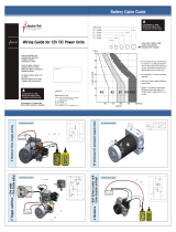
Maintenance Manual Contains:
• Warranty Information
• Warnings
• Service Time Chart
• Periodic Maintenance Checklist
• Service and Maintenance Instructions
• Decals
• Hydraulic & Electrical System Diagrams
• Troubleshooting


LIFT CORP.
11921 Slauson Ave.
Santa Fe Springs, CA. 90670
CUSTOMER SERVICE:
TELEPHONE (562) 464-0099 TOLL FREE (800) 227-4116
FAX: (888) 771-7713
WARRANTY/ RMA POLICY & PROCEDURE
NOTE: For latest version of all Manuals (and replacements), download the
Manuals from Maxon’s website at www.maxonlift.com.
LIFTGATE WARRANTY
Type of Warranty: Full Parts and Labor
Term of Warranty: Standard Liftgates - 2 years from ship date or 6,000 cycles
Premium Liftgates - 2 years from ship date or 10,000 cycles
This warranty shall not apply unless the product is installed, operated and maintained in accordance with MAXON Lift’s specifi cations as set forth in
MAXON Lift’s Installation, Operation and Maintenance manuals. This warranty does not cover normal wear, maintenance or adjustments, damage or
malfunction caused by improper handling, installation, abuse, misuse, negligence, or carelessness of operation. In addition, this warranty does not
cover equipment that has had unauthorized modifi cations or alterations made to the product.
MAXON agrees to replace any components which are found to be defective during the fi rst 2 years of service, and will reimburse for labor based on
MAXON’s Liftgate Warranty Flat Rate Schedule. (Copy of the Flat Rate is available at www.maxonlift.com.)
All warranty repairs must be performed by an authorized MAXON warranty facility. For any repairs that may exceed $500, including parts and labor,
MAXON’s Technical Service Department must be notifi ed and an “Authorization Number” obtained.
All claims for warranty must be received within 30 Days of the repair date, and include the following information:
1. Liftgate Model Number and Serial Number
2. The End User must be referenced on the claim
3. Detailed Description of Problem
4. Corrective Action Taken, and Date of Repair
5. Parts used for Repair, Including MAXON Part Number(s)
6. MAXON R.M.A. # and/or Authorization # if applicable (see below)
7. Person contacted at MAXON if applicable
8. Claim must show detailed information i.e. Labor rate and hours of work performed
Warranty claims can also be placed online at www.maxonlift.com. Online claims will be given priority processing.
All claims for warranty will be denied if paperwork has not been received or claim submitted via Maxon website for processing by MAXON’s Warranty
Department within 30 days of repair date.
All components may be subject to return for inspection, prior to the claim being processed. MAXON products may not be returned without prior written
approval from MAXON’s Technical Service Department. Returns must be accompanied by a copy of the original invoice or reference with original
invoice number and are subject to a credit deduction to cover handling charges and any necessary reconditioning costs. Unauthorized returns will be
refused and will become the responsibility of the returnee.
Any goods being returned to MAXON Lift must be pre-approved for return, and have the R.M.A. number written on the outside of the package in plain
view, and returned freight prepaid. All returns are subject to a 15% handling charge if not accompanied by a detailed packing list. Returned parts
are subject to no credit and returned back to the customer. Defective parts requested for return must be returned within 30 days of the claim date for
consideration to:
MAXON Lift Corp.
10321 Greenleaf Ave., Santa Fe Springs, CA 90670
Attn: RMA#__
MAXON’s warranty policy does not include the reimbursement for travel time, towing, vehicle rental, service calls, oil, batteries or loss of income due to
downtime. Fabrication or use of non Maxon parts, which are available from MAXON, are also not covered.
MAXON’s Flat Rate Labor Schedule takes into consideration the time required for diagnosis of a problem.
All Liftgates returned are subject to inspection and a 15% restocking fee. Any returned Liftgates or components that have been installed or not returned
in new condition will be subject to an additional reworking charge, which will be based upon the labor and material cost required to return the Liftgate or
component to new condition.
PURCHASE PART WARRANTY
Term of Warranty: 1 Year from Date of Purchase.
Type of Warranty: Part replacement only. MAXON will guarantee all returned genuine MAXON replacement parts upon receipt and inspection of parts
and original invoice.
All warranty replacements parts will be sent out via ground freight. If a rush shipment is requested, all freight charges will be billed to the requesting
party.

TABLE OF CONTENTS
SUMMARY OF CHANGES: M-16-12, REVISION B ............................................................. 7
WARNINGS ........................................................................................................................... 8
SAFETY INSTRUCTIONS .................................................................................................... 9
PERIODIC MAINTENANCE ................................................................................................ 10
DECALS - WELDING CAUTION ......................................................................................... 10
DECALS ...............................................................................................................................11
PREVENTATIVE MAINTENANCE CHECKLIST ................................................................. 13
PERIODIC MAINTENANCE CHECKS ................................................................................ 15
BMR LUBRICATION DIAGRAM .......................................................................................... 16
CHECKING HYDRAULIC FLUID ........................................................................................ 17
CHANGING HYDRAULIC FLUID ........................................................................................ 19
BLEEDING HYDRAULIC SYSTEM ..................................................................................... 20
ADJUSTMENT ....................................................................................................................21
CHECK & ADJUST CLEARANCE OF RUNNER PADS ...................................................... 21
PLATFORM CHAIN ADJUSTMENT .................................................................................... 26
PLATFORM ADJUSTMENT ............................................................................................... 28
REPLACING PARTS ..........................................................................................................29
CLOSING CYLINDER REPLACEMENT ............................................................................ 29
LIFTING CYLINDER REPLACEMENT ............................................................................... 31
RUNNER REPLACEMENT ................................................................................................. 35
HYDRAULIC SYSTEM DIAGRAMS .................................................................................. 54
PUMP & MOTOR SOLENOID OPERATION - GRAVITY DOWN ........................................ 54
PUMP & MOTOR SOLENOID OPERATION - POWER DOWN .......................................... 55
ELECTRICAL CONTROLLER DIAGRAMS ....................................................................... 56

CONTROLLER INDICATIONS ............................................................................................ 56
CONTROLLER INPUT LED(S) NOT ILLUMINATED & OUTPUT LED(S) NOT
ILLUMINATED .................................................................................................................... 60
CONTROLLER INPUT LED(S) ILLUMINATED, BUT OUTPUT LED(S) NOT
ILLUMINATED .................................................................................................................... 61
CONTROLLER INPUT LED(S) & OUTPUT LED(S) ILLUMINATED, BUT LOSS OF LIFT-
GATE FUNCTION .............................................................................................................. 62
GRAVITY DOWN HYDRAULIC SCHEMATIC ..................................................................... 63
GRAVITY DOWN HYDRAULIC LINES IDENTIFICATION .................................................. 65
TORQUE VALUES FOR HYDRAULIC CONNECTORS ..................................................... 67
POWER DOWN HYDRAULIC SCHEMATIC ....................................................................... 68
POWER DOWN HYDRAULIC LINES IDENTIFICATION .................................................... 69
ELECTRICAL SYSTEM DIAGRAMS ................................................................................. 71
INTERCONNECTING ELECTRICAL SCHEMATIC - GRAVITY DOWN ............................. 71
GRAVITY DOWN SINGLE & DUAL PUMP ELECTRICAL SCHEMATIC ............................ 72
INTERCONNECTING ELECTRICAL SCHEMATIC - POWER DOWN ............................... 73
POWER DOWN SINGLE & DUAL PUMP ELECTRICAL SCHEMATIC .............................. 74
WIRING HARNESS TWIST-LOCK CONNECTORS ........................................................... 75
BMR ELECTRICAL VALUES............................................................................................... 76
TROUBLESHOOTING ........................................................................................................ 77
PLATFORM WILL NOT RAISE & MOTOR WILL NOT RUN (MTE PUMP) ......................... 77
PLATFORM WILL NOT RAISE & MOTOR WILL NOT RUN (BUCHER PUMP) ................. 78
PLATFORM WILL NOT RAISE & MOTOR RUNS (MTE PUMP) ........................................ 79
PLATFORM WILL NOT RAISE & MOTOR RUNS (BUCHER PUMP) ................................. 81
PLATFORM WILL NOT RAISE LOAD AT RATED CAPACITY (MTE PUMP) ...................... 83

PLATFORM WILL NOT RAISE LOAD AT RATED CAPACITY (BUCHER PUMP) .............. 84
PLATFORM RAISES AND LOWERS UNEVENLY .............................................................. 85
PLATFORM RAISES HALFWAY & STOPS (MTE PUMP) .................................................. 87
PLATFORM RAISES HALFWAY & STOPS (BUCHER PUMP) ........................................... 89
PLATFORM WILL NOT FOLD (MTE PUMP) ...................................................................... 91
PLATFORM WILL NOT FOLD (BUCHER PUMP) ............................................................... 93
PLATFORM WILL NOT UNFOLD (MTE PUMP) ................................................................. 95
PLATFORM WILL NOT UNFOLD (BUCHER PUMP) .......................................................... 97
POWER OPEN/CLOSE RELIEF VALVE PRESSURE SETTING (MTE PUMP) ................. 99
POWER OPEN/CLOSE RELIEF VALVE PRESSURE SETTING .................................... 100
(BUCHER PUMP) .............................................................................................................. 100
LIFTING LINE RELIEF VALVE PRESSURE SETTING (MTE PUMP) .............................. 101
LIFTING LINE RELIEF VALVE PRESSURE SETTING (BUCHER PUMP) ....................... 102
TROUBLESHOOTING - GRAVITY DOWN ....................................................................... 103
PLATFORM WILL NOT LOWER (MTE PUMP) ................................................................. 103
PLATFORM WILL NOT LOWER (BUCHER PUMP) ......................................................... 105
PLATFORM LOWERS SLOWLY (MTE PUMP) ................................................................. 107
PLATFORM LOWERS SLOWLY (BUCHER PUMP) ......................................................... 109
TROUBLESHOOTING - POWER DOWN ..........................................................................111
RELIEF VALVE PRESSURE SETTING (MTE PUMP) .......................................................111
RELIEF VALVE PRESSURE SETTING (BUCHER PUMP) ...............................................112
PLATFORM WILL NOT LOWER (MTE PUMP) ..................................................................113
PLATFORM WILL NOT LOWER (BUCHER PUMP) ..........................................................115
PLATFORM LOWERS SLOWLY (MTE PUMP) ..................................................................117
PLATFORM LOWERS SLOWLY (BUCHER PUMP) ..........................................................119

SUMMARY OF CHANGES: M-16-12, REVISION B
PAGE DESCRIPTION OF CHANGE
COVER Updated REV. and date of release.
76
Updated coil resistance and ampere values for Bucher pump solenoid valves H, E, C &
B. Removed coil pull-in values.

11921 Slauson Ave. Santa Fe Springs, CA. 90670 (800) 227-4116 FAX (888) 771-7713
8
• Do not stand, or allow obstructions, under the platform when lowering the Liftgate. Be sure your
feet are clear of the Liftgate.
• Keep fi ngers, hands, arms, legs, and feet clear of moving Liftgate parts (and platform
edges) when operating the Liftgate.
• Disconnect Liftgate power cable from battery before repairing or servicing Liftgate.
Comply with the following WARNINGS and SAFETY INSTRUCTIONS while maintaining
Liftgates. See Operation Manual for operating safety requirements.
• If it is necessary to stand on the platform while maintaining the Liftgate, keep your feet and any
objects clear of the inboard edge of the platform. Your feet or objects on the platform can become
trapped between the platform and the Liftgate extension plate.
WARNING
!
• Correctly stow platform when not in use. Extended platforms could create a hazard for
people and vehicles passing by.
• Recommended practices for welding on steel parts are contained in the current AWS (American
Welding Society) D1.1 Structural Welding Code - Steel. Damage to Liftgate and/or vehicle, and
personal injury could result from welds that are done incorrectly.
• Recommended practices for welding on aluminum parts are contained in the current AWS
(American Welding Society) D1.2 Structural Welding Code - Aluminum. Damage to Liftgate
and/or vehicle, and personal injury could result from welds that are done incorrectly.
WARNINGS
• Recommended practices for welding galvanized steel are contained in the current AWS (Ameri-
can Welding Society) D19.0 Welding Zinc-Coated Steel. Damage to Liftgate and/or vehicle, and
personal injury can result from welds that are done incorrectly.
• Remove all rings, watches and jewelry before doing any electrical work.

11921 Slauson Ave. Santa Fe Springs, CA. 90670 (800) 227-4116 FAX (888) 771-7713
9
SAFETY INSTRUCTIONS
• If an emergency situation arises (vehicle or Liftgate) while operating the Liftgate, release the con-
trol switch to stop the Liftgate.
• A correctly installed Liftgate operates smoothly and reasonably quiet. The only noticeable noise
during operation comes from the power unit while the platform is raised. Listen for scraping, grat-
ing and binding noises and correct the problem before continuing to operate Liftgate.
• Use only Maxon Authorized Parts for replacement parts. Provide Liftgate model and serial num-
ber information with your parts order. Order replacement parts from:
MAXON LIFT CORP. Customer Service
11921 Slauson Ave., Santa Fe Springs, CA 90670
Online: www.maxonlift.com
Express Parts Ordering: Phone (800) 227-4116 ext. 4345
Email: Ask your Customer Service representative
• Keep decals clean and legible. If decals are illegible or missing, replace them. Free replacement
decals are available from Maxon Customer Service.
• Consider the safety and location of bystanders and location of nearby objects when operating the
Liftgate. Stand to one side of the platform while operating the Liftgate.
• Wear appropriate safety equipment such as protective eyeglasses, faceshield and clothing while
performing maintenance on the Liftgate and handling the battery. Debris from drilling and contact
with battery acid may injure unprotected eyes and skin.
• Do not allow untrained persons or children to operate the Liftgate.
• Be careful working by an automotive type battery. Make sure the work area is well ventilated and
there are no fl ames or sparks near the battery. Never lay objects on the battery that can short the
terminals together. If battery acid gets in your eyes, immediately seek fi rst aid. If acid gets on your
skin, immediately wash it off with soap and water.
• Read and understand the instructions in this Maintenance Manual before performing mainte-
nance on the Liftgate.
• Before operating the Liftgate, read and understand the operating instructions in Operation
Manual.
• Comply with all WARNING and instruction decals attached to the Liftgate.
SAFETY INSTRUCTIONS

11921 Slauson Ave. Santa Fe Springs, CA. 90670 (800) 227-4116 FAX (888) 771-7713
10
Comply with welding CAUTION decals on Lift-
gate runners.
CAUTION
NOTE: See following pages to fi nd the other decals on
Liftgate.
PERIODIC MAINTENANCE
FIG. 10-1
DECALS - WELDING CAUTION

11921 Slauson Ave. Santa Fe Springs, CA. 90670 (800) 227-4116 FAX (888) 771-7713
11
PERIODIC MAINTENANCE
FIG. 11-1
DECALS
NOTE: Ensure there is no residue, dirt, or corrosion where decals are attached.
If necessary, clean surface before attaching decals.
STOW WARNING
DECAL
P/N 282847-01
FAMILY OWNED DECAL
(2 PLACES)
P/N 283445-01
SERIAL PLATE
FAMILY OWNED
DECAL
P/N 283445-01
DECAL “C”
DECAL “A”
DECAL “B”
DECAL “D”
YELLOW
ALIGNMENT TAPE
P/N 090175-14
DECAL “E”
CAUTION DECAL
(2 PLACES)
P/N 260552
WARNING DECAL
P/N 288966-01
NOTE: Decals on the Liftgate are attached at the
factory.
DECAL “F”

11921 Slauson Ave. Santa Fe Springs, CA. 90670 (800) 227-4116 FAX (888) 771-7713
12
TABLE 12-1
DECAL SHEET
FIG. 12-1
MODEL ORDER P/N DECAL “C”
BMR-35 289163-01 3500 LBS. [1600 KG]
BMR-44 289163-02 4400 LBS. [2000 KG]
BMR-55 289163-03 5500 LBS. [2500 KG]
BMR-66 289163-04 6600 LBS. [3000 KG]
(REFER TO TABLE 12-1)

11921 Slauson Ave. Santa Fe Springs, CA. 90670 (800) 227-4116 FAX (888) 771-7713
13
MAXON BMR LIFTGATE
PREVENTATIVE MAINTENANCE CHECKLIST
PERIODIC MAINTENANCE
PM Interval: Quarterly / Annual
Date:
/ /
Equipment: W/O # Location:
Mechanic: Serial # Model #
Check Appropriate Box. “”
MAXON Quarterly Liftgate PM Procedures
Satisfactory Repair Required Corrected
1
Check your company’s maintenance records to verify when quarterly and
annual PM’s are due.
Satisfactory Repair Required Corrected
2
Check for oil leaks: cylinders, fi ttings, hoses, valves, oil fi lter and fi ttings
inside of pump box.
Satisfactory Repair Required Corrected
3
Check for damage: bent ramps, platform, columns, runners & hydraulic
tubes.
Satisfactory Repair Required Corrected
4 Check for loose or missing nuts, bolts, covers, roll pins, screws and pins.
Satisfactory Repair Required Corrected
5
Check for cracked welds: columns, runners, platform, chain arms, pump
box and door frame.
Satisfactory Repair Required Corrected
6
Check platform lowering speed: Range is 8-22 seconds BMR-35/-44 or 12-
27 seconds BMR-55/66 with unloaded platform. Check “D” valves for proper
operation.
Satisfactory Repair Required Corrected
7 Check platform pins and couplers. Check roller assemblies.
Satisfactory Repair Required Corrected
8
Check platform raising speed: Range is 9-21 seconds BMR-35/-44 or
13-26 seconds BMR-55/-66 with unloaded platform.
Satisfactory Repair Required Corrected
9 Check open and close speed: Range is 4-7 seconds in either direction.
Satisfactory Repair Required Corrected
10 Check platform pins and couplers. Check roller assemblies on runners.
Satisfactory Repair Required Corrected
11
Check switches, circuit breaker & wiring connections on Liftgate as well as
inside pump box. Also check that ground strap connections are tight.
Satisfactory Repair Required Corrected
12 Check gear pump for unusual noise (i.e. squealing or excessive RPM).
Satisfactory Repair Required Corrected
13
Check oil level with platform stowed. Refer to oil decal inside pump cover.
The sight glass should be half full. Check oil for contamination. Change if
needed.
Satisfactory Repair Required Corrected
14 Check batteries: load test, corrosion, cables, hold downs and water level.
Satisfactory Repair Required Corrected
15 Check platform chains for wear each time maintenance is performed.
Satisfactory Repair Required Corrected
16 Check operation of cart stop ramps (if equipped).
Satisfactory Repair Required Corrected
17 Check all charging and ground cable connections.
Satisfactory Repair Required Corrected
18
Check operation of the 2 platform fl ashing lights when platform is unfolding
and unfolded. If the lights stop working, the batteries cannot be replaced
and the lights cannot be repaired. Order replacement lights.
Satisfactory Repair Required Corrected
19
Pump EP synthetic grease in each lube fi tting at 2 platform pivots and the 2
roller axles on the 4 tandems (if equipped with fi ttings). Wipe away grease
seepage. Ensure each of the tandem rollers is clean and free of grease.
Satisfactory Repair Required Corrected
20
Follow your company’s guidelines for completing PM stickers and
maintenance records for the Liftgate.
MAXON Annual Liftgate PM Procedures
Satisfactory Repair Required Corrected
21 Replace spin-on fi lter in pump box. Change hydraulic fl uid if contaminated.
Satisfactory Repair Required Corrected
22 Inspect wear on slide pads, on the RH and LH runners.
For more detailed information, please refer to the applicable sections in this Maintenance Manual and
the separate Parts Manual. Use only genuine Maxon replacement parts for all repairs.

11921 Slauson Ave. Santa Fe Springs, CA. 90670 (800) 227-4116 FAX (888) 771-7713
14
THIS PAGE INTENTIONALLY LEFT BLANK.

11921 Slauson Ave. Santa Fe Springs, CA. 90670 (800) 227-4116 FAX (888) 771-7713
15
NOTE: Photocopy the PM CHECKLIST on the preceding page to help keep track of peri-
odic maintenance on the Liftgate. Keep completed form with maintenance records.
Annually
Quarterly
PERIODIC MAINTENANCE CHECKS
Never operate the Liftgate if parts are loose or missing.
WARNING
Check the hydraulic fl uid level in the pump reservoir. Refer to the CHECKING HYDRAULIC
FLUID procedure in the PERIODIC MAINTENANCE section.
Pump EP synthetic grease in fi tting on 2 platform pivots and roller axels on 4 tandems.
Check for worn out links on each of the two platform chains.
Check each end of the two platform chains to make sure they are fastened properly.
Check that all roll pins are in place and protrude evenly from both sides of hinge pin col-
lar. Replace roll pins if necessary.
Check that all WARNING and instruction decals are in place and legible.
Check electrical wiring for chaffi ng and make sure wiring connections are tight and free
of corrosion. MAXON recommends using dielectric grease on all electrical connections.
Check hoses and fi ttings for chaffi ng and fl uid leaks. Replace if necessary.
Keep track of the grade of hydraulic fl uid in the pump reservoir. Never mix two different
grades of fl uid.
If hydraulic fl uid appears contaminated, refer to the CHANGING HYDRAULIC FLUID
procedure on following page.
Check for rust and oily surfaces on Liftgate. If there is rust or oil on the Liftgate, clean it
off. Touch up the paint where bare metal is showing.
Damaged cylinder seals and contaminated hydraulic fl uid can result from paint-
ing the polished portion of the cylinder rod. To prevent damage, protect the
exposed polished portion of the cylinder rod while painting.
CAUTION
Change spin-on oil fi lter.
Inspect for wear on slide pads on the RH & LH runners.
!
NOTE: When replacing parts, refer to the Parts Portal on the Maxon website for genuine
MAXON replacement parts.
Check pump box cover seal. Replace seal if damaged.

11921 Slauson Ave. Santa Fe Springs, CA. 90670 (800) 227-4116 FAX (888) 771-7713
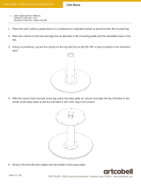
16
FIG. 16-1
NOTE: Lube fi ttings are shown for the tandem roller axles on the LH runner and the pivot
on the LH side of platform. There are also lube fi ttings in the same location on the
tandem roller axles for the RH runner and the pivot on the RH side of the platform.
Refer to the PERIODIC MAINTENANCE CHECKS and PREVENTATIVE MAIN-
TENANCE CHECKLIST for the recommended grease and maintenance interval.
BMR LUBRICATION DIAGRAM

11921 Slauson Ave. Santa Fe Springs, CA. 90670 (800) 227-4116 FAX (888) 771-7713
17
CHECKING HYDRAULIC FLUID
1. Stow the platform in the up position. Refer
to Operation Manual for instructions.
NOTE: If the hydraulic fl uid in the reservoir is contaminated, do the CHANGING
HYDRAULIC FLUID procedure in this section.
CAUTION
Keep dirt, water and other contaminants from entering the hydraulic system.
Before opening the hydraulic fl uid reservoir fi ller cap, drain plug and hydraulic
lines, clean up contaminants that can get in the openings. Also, protect the
openings from accidental contamination.
Never mix synthetic fl uids with conventional hydraulic fl uids. Hydraulic system
must be purged if the fl uids are mixed.
2. Open the pump box cover to gain
access to pump reservoir (FIG.
17-1).
4. Reinstall fi ller cap (FIG. 17-1) and
close the pump box cover.
NOTE: Exxon Univis HVI-13 hydraulic fl uid is recommended for operating tem-
peratures of -40 to +120° F. Refer to decal in pump box. The ISO-15 fl uids
in TABLE 19-1 may be used if the recommended fl uids are unavailable. If
necessary, the ISO-32 fl uids in TABLE 19-2 may be used where ordinary
seasonal temperatures are near +100° F or higher.
3. Check if hydraulic fl uid level
is at the full line (FIG. 17-1). If
necessary, remove fi ller cap (FIG.
17-1) and add the correct grade
of hydraulic fl uid until level rises to
the full line (FIG. 17-1).
CHECKING HYDRAULIC FLUID LEVEL
FIG. 17-1
NOTE: Information for checking
hydraulic fl uid level is shown
on a decal on the pump
reservoir.
PERIODIC MAINTENANCE
FILLER CAP
FULL LINE

11921 Slauson Ave. Santa Fe Springs, CA. 90670 (800) 227-4116 FAX (888) 771-7713
18
ISO-32 HYDRAULIC OIL
BRAND PART NUMBER
CHEVRON HIPERSYN 32
KENDALL GOLDEN MV
SHELL TELLUS S2 VX 32
EXXON UNIVIS N-32
MOBIL
DTE-13M, DTE-24,
HYDRAULIC OIL-13
TABLE 18-1
TABLE 18-2
ISO-15 OR MIL-H-5606 TYPE HYDRAULIC OIL
BRAND PART NUMBER
CHEVRON FLUID A, AW-MV-15
KENDALL GLACIAL BLU
SHELL TELLUS S2 VX 15
MOBIL DTE-11M
ROSEMEAD THS FLUID 17111

11921 Slauson Ave. Santa Fe Springs, CA. 90670 (800) 227-4116 FAX (888) 771-7713
19
1. Place empty 5 gallon bucket under drain plug.
GRAVITY DOWN LIFTGATES
4. Reinstall fi ller cap (FIG. 19-1).
POWER DOWN LIFTGATES
1. Place empty 5 gallon bucket under drain plug.
CHANGING HYDRAULIC FLUID
PERIODIC MAINTENANCE
3. Remove fi ller cap (FIG. 19-1).
Refi ll reservoir until hydraulic
fl uid level until level rises to the
full line (FIG. 19-1).
FULL LINE
CAUTION
Keep dirt, water and other contaminants from entering the hydraulic system.
Before opening the hydraulic fl uid reservoir fi ller cap, drain plug and hydraulic
lines, clean up contaminants that can get in the openings. Also, protect the
openings from accidental contamination.
Never mix synthetic fl uids with conventional hydraulic fl uids. Hydraulic system
must be purged if the fl uids are mixed.
NOTE: Exxon Univis HVI-13 hydraulic fl uid is recommended for operating tem-
peratures of -40 to +120° F. Refer to decal in pump box. The ISO-15 fl uids
in TABLE 19-1 may be used if the recommended fl uids are unavailable. If
necessary, the ISO-32 fl uids in TABLE 19-2 may be used where ordinary
seasonal temperatures are near +100° F or higher.
2. Open and lower platform. Remove the drain plug
(FIG. 19-1). Drain hydraulic fl uid from system.
Reinstall drain plug.
FILLER CAP
DRAIN PLUG
HYDRAULIC FLUID
FIG. 19-1
5. Reinstall fi ller cap (FIG. 19-1).
4. Remove fi ller cap (FIG. 19-1).
Refi ll reservoir until hydraulic
fl uid level until level rises to the
full line (FIG. 19-1).
3. Open and lower platform. Remove the drain plug
(FIG. 19-1). Drain hydraulic fl uid from system.
Reinstall drain plug.
2. If Liftgate is in power down mode, change to
gravity down mode. Push the POWER DOWN
ON DEMAND SWITCH so it is not illuminated.
Refer to Operation Manual.

11921 Slauson Ave. Santa Fe Springs, CA. 90670 (800) 227-4116 FAX (888) 771-7713
20
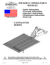
BLEEDING HYDRAULIC SYSTEM
1. Use UP/DOWN toggle switch to lower the
opened platform to the ground.
2. Loosen, but do not disconnect, the nut
connecting hydraulic line to fi tting on
pressure compensated fl ow control valve
(FIG. 20-1) at top of both cylinders.
3. Set the UP/DOWN switch on the RH runner in
the UP position for approximately one second
and then release the switch. Wait ten seconds
and then switch to UP and release. Repeat
this step until there is no air bubbling from the
loosened line fi ttings.
5. Use UP/DOWN toggle switch to raise and
lower the platform to make sure the Liftgate
operates correctly.
4. Tighten nut on hydraulic line (FIG. 20-1).
FIG. 20-1
NOTE: Perform this procedure at a place where Liftgate platform can be
lowered to lowest point of travel. Get a helper to operate Liftgate
control switch.
PRESSURE COMPENSATED
FLOW CONTROL VALVE
NUT
(HYDRAULIC
LINE)
FITTING
/