Page is loading ...

Installation
Instruction
C i10/ C i20
www.contura.eu

GB
18
www.contura.eu
EC Declaration of
conformity
MANUFACTURER
Name NIBE AB / Contura
Address Box 134, Skulptörvägen 10, SE-285 23 Markaryd
Place of manufacture Markaryd, Sweden
PRODUCT
Product type Insert lit with solid fuels
Type designation Contura Insert 10 and 20
Standard EN 13229
Intended for use Heating of living accommodation
Fuels Wood logs
Special conditions None
CE-MARKING Ci10 Ci20
Nominal output 9 kW 10kW
Fuel type Wood logs Wood logs
Flue gas temperature 265° C 280° C
Energy efficiency 81% 81%
Emission of CO 0,09% 0,07%
Installation distances See installation instructions
Appendix
Lighting and installation instructions
Niklas Gunnarsson
Business area manager NIBE STOVES
CERTIFICATE
Manufacturer's declaration
The inserts are approved by the Swedish National Testing and Research Institute, SP SITAC
and fulfils the applicable rules for CE marking. Manufacture of the product has taken place in
accordance with those documents that are the basis for the relevant type approval certification
and the required manufacturing checks.

GB
19
NOTE!
Report installation of a stove to your local
authority.
The owner of the house is personally responsible
for ensuring compliance with the mandatory safety
requirements and must have the installation approved by
a qualified inspector. Your local chimney sweep must also
be informed about the installation as this will affect the
routines for regular chimney-sweeping services.
Table of contents
General 20
Important dimensions 21
Prior to installation 22
Installation 26
Connection to chimney 27
Recessing the insert 29
WARNING!
During operation some of the surfaces of the inserts
become extremely hot and can cause burn injuries if
touched. Be aware of the strong heat radiated through
the hatch glass. Placing flammable material closer than
the safe distance indicated may cause a fire. Pyre lighting
can cause quick gas ignition with the risk of damage to
property and personal injury.
A warm welcome to Contura.
A warm welcome to the Contura family. We hope you
will get a great deal of pleasure from your new stove.
As a new owner of a Contura stove, you have secured
a product with timeless design and long service life.
Contura also has a combustion process that is both
environmentally friendly and efficient, for the best heat
production.
Read through these installation instructions carefully
before installation. Read how to best light your stove in
the lighting instructions.
CONTENTS

GB
20
General
This manual contains instructions about
how the Contura i10 and i20 must be
constructed and installed. In order for
the Insert’s function and safety to be
guaranteed, we recommend that the
installation is carried out by a professional.
Our Contura dealers can recommend
suitable technicians, information about our
dealers can be found at www.contura.eu
Instructions for lighting are also supplied
with the insert. Read them carefully and
keep them safe for future use.
Eldstadsbeklädnad
Diffusor
Rökhylla
Spjäll
Typskylt
Asklåda
Roster
Motvikt
Servicelucka
Justerbara fötter
Anslutningsstos
Bottenisolering
Rosterhandtag
Hearth cladding
Smoke baffle
Damper
Type plate
Ash-pan
Bottom insulation
Connector
Adjustable feet
Service hatch
Counter weight
Grate
Grate handle
Diffuser
GENERAL
Structural support
Check that wooden joists have the
sufficient load capacity for the insert,
chimney and construction parts that
are used when recessing. A completed
installation can usually be positioned on
a normal wooden joist in a single-family
house as long as the total weight does not
exceed 400 kg.
Hearth plate
If the floor under the stove is flammable,
it must be protected by a non-flammable
material e.g. natural stone, concrete or 0.7
mm thick metal. The floor in front of the
hearth opening must be protected against
any falling embers using non-flammable
material that covers an area at least 300
mm in front and 100 mm along each side
of the hatch opening. A painted metal or
toughened glass hearth plate is available as
an accessory.
Technical Data
Model i10 i20
Power output 6-12 kW 6-12 kW
Nominal output 9 kW 10 kW
Ef ficiency 81% 81%
Weight (kg) 215 240
Width (mm) 785 685
Depth (mm) 515 515
Height (mm) 1315 1535
Connector diameter Ø200 mm ext.
Type approved in accordance with:
European standard EN-13229
DIN plus
Bauart 1
15A B-VG
Test report no. i10: RRF-29 09 2077,
i20: RRF-29 09 2078
The inserts are type approved and can
be connected to a chimney dimensioned
for a flue gas temperature of 350°C, the
external diameter of the connector is Ø200
mm. Supply air from the open air should
be used as combustion air. Follow the
recommendations for cross section areas
for convection air.
Chimney
The insert requires a draft in the chimney
of at least –12 Pa. The draft is affected
both by the length and area of the chimney,
and by how well sealed it is.
• Once the lighting phase is complete,
this insert must be operated with the
door closed because of the risk of smoke
entering the room. Always open the door
carefully and slowly to prevent blow back
because of the changing pressure in the
stove.
• Carefully check that the chimney is sealed
and that there is no leakage around soot
hatches and flue connections.
Note that a flue with sharp bends and
horizontal routing reduces the draught in
the chimney. Maximum horizontal flue is 1
m, on the condition that the vertical flue
length is at least 5 m. It must be possible
to sweep the full length of the flue and the
soot hatches must be easily accessible.

GB
21
Important dimensions
C i10
1315 ±10
1230 ±10
1070 ±10
120
10
450
320 ±10
515
200
40 ±10
Air inlet Ø100
Ø 200
785
680
1535 ±10
1450 ±10
1290 ±10
5
670
320 ±10
515
200
40 ±10
Air inlet Ø100
Ø 200
685
580
C i20
IMPORTANT DIMENSIONS

GB
22
Unpacking and removing loose parts
Before moving the insert, the loose parts inside the insert
should be removed by removing the screws, which makes up the
transport locking device for the hatch’s counter weight. Check
that both wires are in the grooves for the sheaves before the
hatch is opened and the loose parts can be removed. Before
moving the insert from the pallet, transport lock the hatch again
by reinstalling the screws on the counterweight. The insert is
secured to the pallet via two runners, slacken off the screws and
bend the mounting lugs to the side, reinstall the screws on the
legs before removing the insert from the pallet.
Prior to installation
Transportsäkring
Important!
Check wire routing and remove
the transport locking device!
Transport locking device
PRIOR TO INSTALLATION

GB
23
Function check
Perform a function check on the Insert as follows:
Use the adjustable feet to level the insert. Slacken off the two
transport screws that hold the counter weight and at the same
time check that both wires are in the sheaves. Check that the
hatch can be opened and closed.
Check that the damper knob can be moved back and forth to the
max and min marks on the hatch.
Important!
The hatch runners are lubricated at the factory, with
special grease that can withstand high temperatures. This
type of grease is usually difficult to find on the market and
we recommend contacting a Contura dealer to order this
special grease when lubricating the runners.
Cleaning the hatch glass
If necessary, the hatch can easily be cleaned of soot or ash.
Open the two catches by pressing them as illustrated; after
the catches have opened the hatch will fall forwards to a limit
position for cleaning. To close the hatch, move the hatch back
into the catches, which are pushed back to their original position.
PRIOR TO INSTALLATION

GB
24
Self-closing hatch
The insert can be supplied with a self-closing hatch. First open
the hatch according to section “Cleaning the hatch glass”, then
remove the four screws to release the Upper member. Remove
the two screws that hold the spring assembly, install the weight
to the upper member and reinstall the spring assembly in the
upper screw holes. Reinstall the Upper member using the four
screws. The insert can now be supplied with the self-closing
hatch.
Installing removable parts
Removing the hatch from the insert facilitates the installation
of the hearth surround on the I 20. If the insert is recessed,
removal of the hatch is made easier if the damper knob is
removed. After the catches have been opened the hatch will fall
forward to a limit position. Now lift the hatch and at the same
time move it to the left so that the right side releases from its
mounting, then tilt the hatch out. Assembly takes place in the
reverse order.
2
1
Spring assembly
Weight
Upper member
PRIOR TO INSTALLATION

GB
25
Start by placing the insulation panel in the bottom of the Insert. Start installing the two lower parts of the hearth surround, then
continue with the left back section followed by the left side, finally install the right back section and side.
Smoke baffle.
PRIOR TO INSTALLATION
Prior to positioning the smoke baffle on
top of the hearth surround’s sides The
diffuser must be positioned up inside the
insert’s heat exchanger, the diffuser must
rest against the front edge of the heat
exchanger, at the rear edge there are
hooks that fit into the diffuser.
Position the ash-pan and
cast-iron grate.

GB
26
Ensure that the installation is approved by a certified chimney
sweep, who can also provide information on which national and
regional regulations apply. Also ensure that a function check of
the hatch opening mechanism and damper control is performed
according to the “Function check” section.
Installation
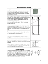
Supply of combustion air
Combustion air can be provided directly via a
duct from outside, or indirectly via a vent in
the outer wall of the room where the stove
is to be placed. The amount of combustion
air that is used for combustion is approx. 30
m3/h.
Some installation alternatives are shown to
the right.
The air duct connection on the stove has
an external diameter of Ø100 mm. In hot
areas, the duct should be insulated with 30
mm mineral wool covered with a moisture
inhibitor for example, aluminium tape.
It is important that the lead-in between the
pipe and the wall (or floor) is sealed using
jointing compound.
A 1 m length of condensation insulated
ducting for combustion air is available as an
accessory.
Alt. 1 Alt. 2
HK
HK
HK
HK
INSTALLATION

GB
27
Connection to chimney
The insert is prepared for top connection, when connecting from
the rear of the insert, the Ø200 connector and cover on the rear
of the insert must be switched over, see “Connecting from the
rear of the insert”.
When connecting to the chimney of less than Ø200, install a
reduction pipe on the existing Ø200 connector. The reduction
pipe must not have an exit diameter less than Ø150. When using
reduction pipes, flue gases can be forced out into the room if the
insert is lit with the hatch open. The condition for connecting to
a Ø150 chimney is that the insert must only be lit with the hatch
closed.
Rear connection to a masonry chimney
Mark out the centre for making a hole in the wall to the flue.
Check that the connection height in the chimney breast
corresponds to the height of the connection pipe from the stove.
IMPORTANT
Always observe the safety distances to
combustible material that steel flues
require
Make a hole large enough so that the wall connector can be
cemented in position with fireproof mortar (not supplied). Let the
mortar dry before the insert is connected to the chimney.
CONNECTION TO ChIMNEy

GB
28
Remove the top and rear panels. Swap the connector and cover.
Install the connection pipe on the connector; ensure that gasket
does not move out of position. When the insert is in position, seal
the connection pipe and wall connector well, use heat-resistant
sealant if necessary. Reinstall the top and rear panels; screw the
covers onto the top panel.
Connecting from the rear of the insert
CONNECTION TO ChIMNEy

GB
29
When recessing the insert, adjacent walls that are not classed as fire walls or are considered unsuitable for heat loads must be protected
by non-combustible material according to the specification below.
All joints on the non-combustible material must be sealed using the manufacture’s recommended method. The area between the insert
and the recess must be ventilated according to the specification/dimension diagrams on page 31.
When top connecting a steel flue please refer to the relevant manufacturer’s installation instructions. Observe the safety distances
to combustible material that steel flues require. Heat radiation from the hatch is strong and is why combustible material must not be
placed closer than 1.5 m in front of the hatch. When recessing, building material must not be in direct contact with the insert due to the
thermal expansion of the insert.
Material requirements
The building material must not be combustible.
The thermal conductivity coefficient may be a maximum of 0.14 W/mK.
The thickness of the building material must always be at least 100 mm.
In cases where the building material’s insulation properties are given as a U-Value, this must be a maximum of 1.4 W/ m²K.
List of suitable materials:
Aerated concrete: =0.12-0.14
Vermiculite: =0.12-0.14
Calcium silicate: =0,09
Sealing
If the recess is to extend to the ceiling, a seal must be made above the convection exhaust. This is to prevent hot air collecting in the
recess closest to the ceiling. The seal must a maximum of 100 mm above the convection exhaust’s upper edge and must be made up of 20
mm thick building boards made of calcium silicate or a panel with at least a 50 mm thickness of rock wool on top.
Convection air
The convection air ventilates the surround, cools the insert and transports the hot air out into the room. The total sum of the effective
cross section area up and down must not be less than the stated values. The air intake must be positioned somewhere between the floor
and the bottom of the insert, up to or on the sides of the recess. The vent must be positioned above the insert’s highest point up to or to
the sides of the recess.
If the air intakes and exhausts are to be located on the sides, the areas on the left and right hand sides must be of equal size to ensure
that the insert is evenly cooled.
Observe the minimum distance up to the ceiling (see diagram on page 31).
Convection air in: 600 cm²
Convection air out: 600 cm²
If the convection outlets are directed upwards the following applies
- the recess must be free-standing or placed against non-combustible walls
- the distance from the air outlet to combustible roof must be at least 700 mm
To service the hatch’s runners, all recess parts built out in front of the moulding below the hatch, e.g. shelves, must be removable.
Note that building regulations apply regarding the area below and in front of the insert, see section ”Hearth plate”.
Recessing the insert
RECESSING ThE INSERT

GB
30
20
800
100
100
100
20
100
100
500
600
20
100
100
100
20
100
100
500
Wall of combustible material
600
20
100
100
100
Wall of non-combustible material, made
of 100 mm aerated concrete in the
recess example.
20
100
100
500
Wall of non-combustible material that
is not in contact with combustible
material and therefore has no minimum
thickness requirement.
Recess example
Chimney breast
550
max 100
20
100
Area ut min. 600 cm
2
Area in min. 600 cm
2
(I 10 min 2100)
(I 20 min 2300)
Note!
The dimensions are the minimum
dimensions, unless otherwise stated.
Note!
The dimensions are the minimum
dimensions, unless otherwise stated.
20
100
RECESSING ThE INSERT

GB
31
550
20
max 100
Area ut min. 600 cm
2
Avtätning
Area in min. 600 cm
2
20
100
(I 10 min 2100)
(I 20 min 2300)
20
550
max 100
20
100
Area ut min. 600 cm
2
Area in min. 600 cm
2
(I 10 min 2100)
(I 20 min 2300)
min 700
100
20
100
Area ut min. 600 cm
2
Area in min. 600 cm
2
(I 10 min 2200)
(I 20 min 2400)
Heat Shield
Area min. 600cm
2
Area min. 600cm
2
Area min. 600cm
2
Area min. 600cm
2
Area min. 600cm
2
Area min. 600cm
2
RECESSING ThE INSERT

NIBE AB · Box 134 · SE-285 23 Markaryd · Sweden
www.contura.eu
Contura reserves the right to change colours, materials,
dimensions and models at any time without special notice.
Your dealer can give you the most up to date information.
Stoves shown in brochures may have extra equipment.
811052 IAV SE-EX Ci10/Ci20-6
2013-08-19
/