Page is loading ...

S4000TH HART
HART Communication Manual
The information and technical data disclosed in
this document may be used and disseminated
only for the purposes and to the extent
specifically authorized in writing by General
Monitors.
Instruction Manual 08-08
General Monitors reserves the right to change
published specifications and designs without
prior notice.
MANS4000TH
Part No. MANS4000THH
Revision
A/08-08

S4000TH HART
ii
Table of Contents
TABLE OF CONTENTS...............................................................................................................II
TABLE OF TABLES....................................................................................................................IV
1.0 INTRODUCTION ....................................................................................................................1
1.1 Scope.........................................................................................................................................1
1.2 Purpose......................................................................................................................................1
1.3 References.................................................................................................................................1
2.0 DEVICE IDENTIFICATION.....................................................................................................1
3.0 PRODUCT OVERVIEW..........................................................................................................2
3.1 Getting Started...........................................................................................................................2
4.0 PRODUCT INTERFACES ......................................................................................................3
4.1 Process Interface.......................................................................................................................3
4.2 Host Interface.............................................................................................................................3
4.3 Local Interfaces, Jumpers, and Switches..................................................................................3
5.0 DEVICE VARIABLES.............................................................................................................3
6.0 DYNAMIC VARIABLES .........................................................................................................3
6.1 Primary Variable = Part Per Million............................................................................................3
6.2 Secondary, Tertiary, and Quaternary Variables: Not Applicable...............................................3
7.0 STATUS INFORMATION .......................................................................................................4
8.0 UNIVERSAL COMMANDS.....................................................................................................5
9.0 COMMON PRACTICE COMMANDS .....................................................................................5
9.1 Supported Commands...............................................................................................................5
9.2 Burst Mode.................................................................................................................................5
9.3 Catch Device Variable................................................................................................................5
10.0 DEVICE SPECIFIC COMMANDS...............................................................................6
10.1 Command #131: Do Abort.........................................................................................................6
10.2 Command #136: Set Alarm Level..............................................................................................6
10.3 Command #137: Set Warn Level...............................................................................................7
10.4 Command #139: Reset Alarm....................................................................................................7
10.5 Command #141: Set Relay (Alarm) Configuration ....................................................................8
10.6 Command #142: Reset Event Happened Flag..........................................................................9
10.7 Command #143: Read Event Logging Counters.......................................................................9
10.8 Command #144: Clear Event Logging Counters.....................................................................10
10.9 Command #145: Read Warning Event Log.............................................................................10
10.10 Command #146: Read Alarm Event Log.................................................................................11
10.11 Command #147: Read Fault Event Log...................................................................................11
10.12 Command #148: Read Maintenance Event Log......................................................................12
10.13 Command #149: Set Clock......................................................................................................13

S4000TH HART
iii
10.14 Command #150: Read Clock...................................................................................................13
10.15 Command #151: Set Run Time Meter.....................................................................................14
10.16 Command #152: Read Run Time Meter..................................................................................14
10.17 Command #154: Set Event Index............................................................................................15
10.18 Command #155: Get Event Index............................................................................................15
10.19 Command #156: Read Calibration Event Log.........................................................................16
10.20 Command #163: Get Fast Changing Information....................................................................16
10.21 Command #164: Get Slow Changing Information...................................................................17
10.22 Command #165: Get Set Up Information.................................................................................18
10.23 Command #170: Set Current Range .......................................................................................19
10.24 Command #189: Set Sensor Life.............................................................................................19
10.25 Command #192: Do Calibration...............................................................................................20
10.26 Command #195: Do Gas Check..............................................................................................20
10.27 Command #196: Set Sensor Rang (Full Scale).......................................................................21
11.0 TABLES....................................................................................................................21
11.1 S4000TH – Device Specific Commands Summary.................................................................21
11.2 S4000TH – Operating Mode - PV Values................................................................................22
11.3 Fault Event Log – Cause Description ......................................................................................22
12.0 PERFORMANCE......................................................................................................23
12.1 Sampling Rates........................................................................................................................23
12.2 Power-up..................................................................................................................................23
12.3 Device Reset............................................................................................................................23
12.4 Self-Test...................................................................................................................................23
12.5 Command Response Delay.....................................................................................................23
12.6 Busy and Delayed-Response ..................................................................................................23
12.7 Long Messages........................................................................................................................23
12.8 Non-Volatile Memory................................................................................................................23
12.9 Operating Modes......................................................................................................................23
12.10 Write Protection........................................................................................................................24
ANNEX A. CAPABILITY CHECKLIST.......................................................................................24
ANNEX B. DEFAULT CONFIGURATION..................................................................................25
ANNEX C. DEVICE DESCRIPTOR LANGUAGE MENU...........................................................26

S4000TH HART
iv
Table of Tables
Table 1: Field Device Identification Data................................................................................................................1
Table 2: Error Status Information ...........................................................................................................................4
Table 3: S4000TH – Common Practice Commands..............................................................................................5
Table 4: S4000TH – Device Specific Commands................................................................................................22
Table 5: S4000TH - Operating Mode - PV Values..............................................................................................22
Table 6: Fault Event Log – Cause Description.....................................................................................................22
Table 7: Command Response Times...................................................................................................................23
Table 8: Capability Checklist................................................................................................................................24
Table 9: Default Configuration..............................................................................................................................25

S4000TH HART
1
1.0 Introduction
1.1 Scope
The S4000TH HART Hydrogen Sulfide (H2S) gas detector complies with HART Protocol Revision 6.0.
This document specifies all of the device specific features and documents HART Protocol implementation
details. The functionality of this Field Device is described sufficiently to allow its proper application in a
process and its complete support in HART capable Host Applications.
1.2 Purpose
This specification is designed to complement the S4000TH Instruction Manual by providing a complete
description of this field device from a HART Communications perspective. This specification is designed
to be a technical reference for HART capable host application developers, system integrators, and
knowledgeable end users.
1.3 References
DOCUMENT NAME
DOCUMENT RELATIONSHIP
HART Communications
Protocol Specifications
This is used to insure compliance with the HART
Communication Protocol.
S4000TH Instruction
Manual
This is the General Monitors S4000TH Product
Instruction Manual.
2.0 Device Identification
The following Table 1 is the Field Device Identification Data for the instrument.
Manufacturer’s
Name
General
Monitors, Inc.
Model Number S4000TH
HART ID Code 223 (DF Hex)
Device Type
Code:
130 (82 Hex)
HART Protocol
Revision
6.0
Device
Revision:
1
Number of
Device Variables
0
Physical Layers
Supported
1
Physical Device
Category
FSK
Table 1: Field Device Identification Data

S4000TH HART
3.0 Product Overview
The S4000TH is an intelligent sensor for the detection of Hydrogen Sulfide (H2S) gas and vapors. The
microprocessor-based electronics processes information at the sensor site, within an explosion-proof
housing. The S4000TH is an Intelligent Sensor from General Monitors. The S4000TH accurately
measures Hydrogen Sulfide gas and reports the measurement as a parts per million (PPM) of the gas.
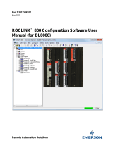
3.1 Getting Started
In order to enable HART communication with the S4000TH detector, users may employ several means
including HART handheld communicators or PC-based systems. Using a PC-based software application
and a HART interface modem, for example, allow operators to access information from the
S4000TH. A
typical setup is illustrated in Figure 1.
Handheld
Terminal
2
Resisto
r
RS-232 USB HART
Interface
Workstation
PC Host
Application
Power
Supply
S4000TH
Figure 1: Connecting a PC to a HART device
Once the detector is installed (see S4000TH Instruction Manual) and connected to a PC, host application,
or handheld terminal, the master will commonly begin communication to the
S4000TH by using the HART
Command #0. The field device will then respond only if its tag matches. The data in the reply to
Command #11 is identical to that of Command #0, so the master can then construct the Unique Identifier
for use with further commands.
NOTE: The handheld device allows for the retrieval of diagnostic information and input of device
settings as needed and should not be used as a permanent part of a safety system.

S4000TH HART
3
4.0 Product Interfaces
4.1 Process Interface
This section describes all interfaces between the devices and the measured process.
4.1.1 Sensor Input Channels
A digital display provides indications and display codes that can be viewed through a window in the
cover. A red LED above the digital display signifies an ALARM condition, while a red LED below the
digital display signifies a WARN condition. Analog signal (4-20 mA) and relays provide remote and/or
discrete indications of the sensor’s operation.
4.2 Host Interface
The HART interface uses the 4 – 20 mA current loop. Refer to the installation manual for connection
details.
4.2.1 Analog Output: S4000TH Mode
The primary variable is proportional to the part per million. 4.0 mA output current corresponds to 0
PPM 20.0 mA output current corresponds to 100 PPM or 100% of full scale
4.3 Local Interfaces, Jumpers, and Switches
4.3.1 Local Controls and Displays
Refer to the Installation Manual for connection details.
4.3.2 Internal Jumpers and Switches
Refer to the Installation Manual for connection details.
5.0 Device Variables
There are no device variables exposed to the user.
6.0 Dynamic Variables
There is only one Dynamic Variable exposed to the user.
6.1 Primary Variable = Part Per Million
The primary variable is proportional to the part per million 4.0 mA output current corresponds to 0 PPM.
20.0 mA output current corresponds to 100 PPM or 100% of full scale. The device mode is the variable,
which corresponds to the Modbus register 0x00.
6.2 Secondary, Tertiary, and Quaternary Variables: Not Applicable
There are none defined for the S4000TH product.

S4000TH HART
4
7.0 Status Information
The error status, which is returned via Common Practice Command #48, is shown in Table 2 and
corresponds to Modbus register 0x02.
Byte Bit Description Class
Device Status
Bits Set
0 Switch Error Error 4,7
1 Internal error (2.5,15V) Error 4,7
2 Not Used Error 4,7
3 Not Used Error 4,7
4 Not Used Error 4,7
5 Fault Status 4,7
6 Warning Status 4,7
1
7 Alarm Status 4,7
0 Not Used N/A
1 Low Supply Voltage Error 4,7
2 Fail to Calibrate Error 4,7
3 Sensor Error Error 4,7
4 Flash Error Error 4,7
5 EEPROM Error Error 4,7
6 Calibration Check Time out Error 4,7
0
7 Set up Error Error 4,7
Table 2: Error Status Information
These bits may be set at power up to indicate an instrument failure. They may also be set by a failure
detected during continuous background diagnostic testing.

S4000TH HART
5
8.0 Universal Commands
Command 3 returns the current loop variable and the primary variable for a total of 9 bytes returned.
Command 9 returns the PV only.
9.0 Common Practice Commands
The following common practice commands are implemented.
9.1 Supported Commands
The following common-practice commands shown in Table 3 are implemented:
Command
Number
Byte
Number
Meaning
Command 38 N/A
Reset Configuration Changed Flag
Command 48 0 Returns Priority Fault, High Byte
Command 48 1 Returns Priority Fault, Low Byte
Command 48 2 Returns error status (same as Modbus register x02), High Byte
Command 48 3 Returns error status (same as Modbus register x02), Low Byte
Command 48 4 Returns Power Cycled Flag
Command 48 5 Returns Event Happened Flag
Command 48 6
Returns 0x01 = “Maintenance Required”or 0x02 = Alarm or
Warning
Command 48 7 Returns 0
Table 3: S4000TH – Common Practice Commands
9.2 Burst Mode
The S4000TH does not support Burst Mode.
9.3 Catch Device Variable
This S4000TH does not support Catch Device Variable.

S4000TH HART
6
10.0 Device Specific Commands
The Device Specific commands are used strictly for the unique features of the S4000TH and at the
discretion of General Monitors. They are described here in Section
10.0 and are summarized in Table 4.
10.1 Command #131: Do Abort
This command aborts calibration or gas check.
Request Data Bytes
Byte Format Description
None N/A N/A
Response Data Bytes
Byte Format Description
0 N/A N/A
Command-Specific Response Codes
Code Class Description
0 Success No Command-Specific Errors
1 - 15 Undefined
16 Error Access Restricted
17 -
127
Undefined
10.2 Command #136: Set Alarm Level
This command sets the Alarm level.
Request Data Bytes
Byte Format Description
0 Unsigned-8 Alarm level, % of FS
Response Data Bytes
Byte Format Description
0 Unsigned-8 Alarm level, % of FS
Command-Specific Response Codes
Code Class Description
0 Success No Command-Specific Errors
1 – 2 N/A Undefined
3 Error Passed Parameter Too Large
4 N/A Undefined

S4000TH HART
7
Code Class Description
5 Error Too Few Data Bytes Received
6 – 15 N/A Undefined
16 Error Access Restricted
17 – 127 N/A Undefined
10.3 Command #137: Set Warn Level
This command sets the Warn level.
Request Data Bytes
Byte Format Description
0 Unsigned-8 Alarm Warn level, % of FS
Response Data Bytes
Byte Format Description
0 Unsigned-8 Alarm Warn level, % of FS
Command-Specific Response Codes
Code Class Description
0 Success No Command-Specific Errors
1 – 2 N/A Undefined
3 Error Passed Parameter Too Large
4 N/A Undefined
5 Error Too Few Data Bytes Received
6 – 15 N/A Undefined
16 Error Access Restricted
17 – 127 N/A Undefined
10.4 Command #139: Reset Alarm
This command resets the latching Warn and Alarm relay.
Request Data Bytes
Byte Format Description
None N/A N/A
Response Data Bytes
Byte Format Description
None N/A N/A
Command-Specific Response Codes

S4000TH HART
8
Code Class Description
0 Success No Command-Specific Errors
1 - 15 Undefined
16 Error Access Restricted
17 - 127 Undefined
10.5 Command #141: Set Relay (Alarm) Configuration
This command configures the relay settings.
Request Data Bytes
Byte Format Description
0 Unsigned-8 Alarm Hi Relay La/nL: 0 – nL, 1 – LA
1 Unsigned-8 Alarm Hi Relay En/dE: 0 – dE, 1 – En
2 Unsigned-8 Alarm Lo Relay La/nL: 0 – nL, 1 – LA
3 Unsigned-8 Alarm Lo Relay En/dE: 0 – dE, 1 – En
Response Data Bytes
Byte Format Description
0 Unsigned-8 Alarm Hi Relay La/nL: 0 – nL, 1 – LA
1 Unsigned-8 Alarm Hi Relay En/dE: 0 – dE, 1 – En
2 Unsigned-8 Alarm Lo Relay La/nL: 0 – nL, 1 – LA
3 Unsigned-8 Alarm Lo Relay En/dE: 0 – dE, 1 – En
Command-Specific Response Codes
Code Class Description
0 Success No Command-Specific Errors
1 - 2 Undefined
3 Error Passed Parameter too large
4 Undefined
5 Error Too Few Data Bytes Received
16 Error Access Restricted
17 – 127 Undefined

S4000TH HART
9
10.6 Command #142: Reset Event Happened Flag
This command resets the Event Happened Flag.
Request Data Bytes
Byte Format Description
None N/A N/A
Response Data Bytes
Byte Format Description
None N/A N/A
Command-Specific Response Codes
Code Class Description
0 Success No Command-Specific Errors
1 – 15 Undefined
16 Error Access Restricted
17 – 127 Undefined
10.7 Command #143: Read Event Logging Counters
This command reads five event logging counters.
Request Data Bytes
Byte Format Description
None N/A N/A
Response Data Bytes
Byte Format Description
0 – 1 Unsigned-16 Warning Event Counter
2 – 3 Unsigned-16 Alarm Event Counter
4 – 5 Unsigned-16 Fault Event Counter
6 – 7 Unsigned-16 Maintenance Event Counter
8 – 9 Unsigned-16 Calibrate Event Counter
Command-Specific Response Codes
Code Class Description
0 Success No Command-Specific Errors
1-127 Undefined

S4000TH HART
10
10.8 Command #144: Clear Event Logging Counters
This command resets the 5 event logging counters to zero.
Request Data Bytes
Byte Format Description
None N/A N/A
Response Data Bytes
Byte Format Description
None N/A N/A
Command-Specific Response Codes
Code Class Description
0 Success No Command-Specific Errors
1-127 Undefined
10.9 Command #145: Read Warning Event Log
This command reads the Warning Event Log as specified by the event log number. Event 0 is the most
recent event. Event 1 is the one just before that and so forth.
Request Data Bytes
Byte Format Description
None N/A N/A
Response Data Bytes
Byte Format Description
0 – 3 Unsigned-32 Event Running Time (in Seconds)
4– 6 Date Event Date: Day, Month, Year – 1900
7 Unsigned-8 Event Hour
8 Unsigned-8 Event Minute
9 Unsigned-8 Event Second
10-13 Unsigned-8 Reserved = 0
Command-Specific Response Codes
Code Class Description
0 Success No Command-Specific Errors
1-127 Undefined

S4000TH HART
11
10.10 Command #146: Read Alarm Event Log
This command reads the Alarm Event Log as specified by the event log number. Event 0 is the most recent
event. Event 1 is the one just before that and so forth.
Request Data Bytes
Byte Format Description
None N/A N/A
Response Data Bytes
Byte Format Description
0 – 3 Unsigned-32 Event Running Time (in Seconds)
4– 6 Date Event Date: Day, Month, Year – 1900
7 Unsigned-8 Event Hour
8 Unsigned-8 Event Minute
9 Unsigned-8 Event Second
10-13 Unsigned-8 Reserved = 0
Command-Specific Response Codes
Code Class Description
0 Success No Command-Specific Errors
1-127 Undefined
10.11 Command #147: Read Fault Event Log
This command reads the Fault Event Log as specified by the event log number. Event 0 is the most recent
event. Event 1 is the one just before that and so forth.
Request Data Bytes
Byte Format Description
None N/A N/A
Response Data Bytes
Byte Format Description
0 – 3 Unsigned-32 Event Running Time (in Seconds)
4– 6 Date Event Date: Day, Month, Year – 1900
7 Unsigned-8 Event Hour
8 Unsigned-8 Event Minute
9 Unsigned-8 Event Second
10-11 Unsigned-8 Reserved = 0

S4000TH HART
12
12-13 Unsigned-16 Event Cause – See device specific table
Command-Specific Response Codes
Code Class Description
0 Success No Command-Specific Errors
1-127 Undefined
10.12 Command #148: Read Maintenance Event Log
This command reads the Maintenance Event Log as specified by the event log number. Event 0 is the
most recent event. Event 1 is the one just before that and so forth.
Request Data Bytes
Byte Format Description
None N/A N/A
Response Data Bytes
Byte Format Description
0 Unsigned-8 Event Log Number
0 – 3 Unsigned-32 Event Running Time (in Seconds)
4– 6 Date Event Date: Day, Month, Year – 1900
7 Unsigned-8 Event Hour
8 Unsigned-8 Event Minute
9 Unsigned-8 Event Second
10-11 Unsigned-8 Reserved = 0
12-13 Unsigned-8 Code: 0-Gas check
Command-Specific Response Codes
Code Class Description
0 Success No Command-Specific Errors
1-127 Undefined

S4000TH HART
13
10.13 Command #149: Set Clock
This command sets the internal real-time clock.
Request Data Bytes
Byte Format Description
0 – 2 Date Date: Day, Month, Year-1900
3 Unsigned-8 Hours
4 Unsigned-8 Minutes
5 Unsigned-8 Seconds
Response Data Bytes
Byte Format Description
0 – 2 Date Date: Day, Month, Year-1900
3 Unsigned-8 Hours
4 Unsigned-8 Minutes
5 Unsigned-8 Seconds
Command-Specific Response Codes
Code Class Description
0 Success No Command-Specific Errors
1 – 4 Undefined
5 Error Too Few Data Bytes Received
6 – 127 Undefined
10.14 Command #150: Read Clock
This command reads the internal real-time clock setting.
Request Data Bytes
Byte Format Description
0 N/A N/A
Response Data Bytes
Byte Format Description
0 – 2 Date Date: Day, Month, Year-1900
3 Unsigned-8 Hours
4 Unsigned-8 Minutes
5 Unsigned-8 Seconds

S4000TH HART
14
Command-Specific Response Codes
Code Class Description
0 Success No Command-Specific Errors
1-127 Undefined
10.15 Command #151: Set Run Time Meter
This command sets the internal run time meter.
Request Data Bytes
Byte Format Description
0 – 3 Unsigned-32 Run Time Meter Value
Response Data Bytes
Byte Format Description
0 – 3 Unsigned-32 Run Time Meter Value
Command-Specific Response Codes
Code Class Description
0 Success No Command-Specific Errors
1 – 4 Undefined
5 Error Too Few Data Bytes Received
6 – 127 Undefined
10.16 Command #152: Read Run Time Meter
This command reads the internal run time meter.
Request Data Bytes
Byte Format Description
0 N/A N/A
Response Data Bytes
Byte Format Description
0 – 3 Unsigned-32 Run Time Meter Value
Command-Specific Response Codes
Code Class Description
0 Success No Command-Specific Errors
1-127 Undefined

S4000TH HART
15
10.17 Command #154: Set Event Index
This command sets the index of logged event to read. 0 – latest event
Request Data Bytes
Byte Format Description
0 Unsigned – 8 Sets index of logged event to read using commands 143 – 146.
Range 0 – 9.
Response Data Bytes
Byte Format Description
0 Unsigned – 8 Event Index
Command-Specific Response Codes
Code Class Description
0 Success No Command-Specific Errors
1 – 2 Undefined
3 Error Passed Parameter Too Large
4 Undefined
5 Error Too Few Data Bytes Received
6 – 127 Undefined
10.18 Command #155: Get Event Index
This command reads the event logged index.
Request Data Bytes
Byte Format Description
None N/A N/A
Response Data Bytes
Byte Format Description
0 Unsigned – 8 Event index
Command-Specific Response Codes
Code Class Description
0 Success No Command-Specific Errors
1-127 Undefined

S4000TH HART
16
10.19 Command #156: Read Calibration Event Log
This command reads the Calibration Event Log as specified by the event log number. Event 0 is the most
recent event. Event 1 is the one just before that and so forth.
Request Data Bytes
Byte Format Description
None N/A N/A
Response Data Bytes
Byte Format Description
0-3 Unsigned-32 Event Running Time (in Seconds)
4-6 Date Event Date: Day, Month, Year – 1900
7 Unsigned-8 Event Hour
8 Unsigned-8 Event Minute
9 Unsigned-8 Event Second
10 Unsigned-8 1 - N/A, 2 – Calibration
Command-Specific Response Codes
Code Class Description
0 Success No Command-Specific Errors
1-127 Undefined
10.20 Command #163: Get Fast Changing Information
This command reads the Fault Event Log as specified by the event log number. Event 0 is the most recent
event. Event 1 is the one just before that and so forth.
Request Data Bytes
Byte Format Description
None N/A N/A
Response Data Bytes
Byte Format Description
0 – 1 Unsigned-16 Mode – depends on instrument
2 – 3 Unsigned-16 Sub Mode – depends on instrument
4 – 7 Float Analog Output
8 – 9 Unsigned-16 Priority Fault
10 – 11 Bit map Error Status
/