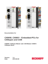
Beckhoff CX8010 User manual

Type
User manual

This manual is also suitable for

Manual
CX8030 / CX8031
CX8030 PROFIBUS-Master / CX8031 PROFIBUS-Slave
1.6
2018-02-09
Version:
Date:
Table of contents
CX8030 / CX8031 3Version: 1.6
Table of contents
1 Notes on the documentation ....................................................................................................................5
1.1 Explanation of symbols................................................................................................................... 6
1.2 Documentation issue status............................................................................................................ 7
2 For your safety...........................................................................................................................................8
2.1 Intended use ................................................................................................................................... 8
2.2 Staff qualification ............................................................................................................................ 9
2.3 Safety instructions .......................................................................................................................... 9
3 Transport and storage ............................................................................................................................11
4 Product overview.....................................................................................................................................12
4.1 CX80xx - System overview........................................................................................................... 12
4.2 CX8030, CX8031 - Introduction.................................................................................................... 14
4.3 Technical data .............................................................................................................................. 16
4.4 Technical data - PROFIBUS......................................................................................................... 17
4.5 CX80xx - MicroSD cards .............................................................................................................. 19
5 Mounting and wiring ...............................................................................................................................20
5.1 Mounting ....................................................................................................................................... 20
5.1.1 Dimensions ......................................................................................................................20
5.1.2 Installation on mounting rails ...........................................................................................20
5.2 Wiring............................................................................................................................................ 23
5.2.1 Power supply....................................................................................................................23
5.2.2 Ethernet............................................................................................................................25
5.2.3 PROFIBUS.......................................................................................................................27
5.3 Changing the battery .................................................................................................................... 31
6 Parameterization and commissioning...................................................................................................32
6.1 DIP switch..................................................................................................................................... 32
6.2 Setting the IP adress .................................................................................................................... 34
6.2.1 IP address........................................................................................................................34
6.2.2 Setting the address via DHCP server ..............................................................................34
6.2.3 Subnet mask ....................................................................................................................34
6.3 Configuration ................................................................................................................................ 36
6.3.1 CX80xx - Operating system .............................................................................................36
6.3.2 Power supply terminal......................................................................................................38
6.3.3 PROFIBUS.......................................................................................................................40
6.3.4 Web Services...................................................................................................................45
6.3.5 Real Time Clock (RTC)....................................................................................................47
6.3.6 1-second UPS (Uninterruptible Power Supply)................................................................48
6.3.7 CPU load..........................................................................................................................49
7 Programming ...........................................................................................................................................50
7.1 Library for CX80xx ........................................................................................................................ 50
7.2 Seconds UPS ............................................................................................................................... 50
7.2.1 Function blocks ................................................................................................................50
7.2.2 Data types........................................................................................................................53
7.3 Diagnostics ................................................................................................................................... 54
7.3.1 FUNCTION F_CX80xx_ADDRESS .................................................................................54
7.4 PROFIBUS ................................................................................................................................... 54
7.4.1 CX8030 ............................................................................................................................54
Table of contents
CX8030 / CX80314 Version: 1.6
7.4.2 CX8031 ............................................................................................................................62
8 Ethernet X001 Interface...........................................................................................................................68
8.1 System introduction ...................................................................................................................... 68
8.1.1 Ethernet............................................................................................................................68
8.1.2 Topology example............................................................................................................70
8.2 ADS-Communication .................................................................................................................... 71
9 PROFIBUS ................................................................................................................................................73
9.1 System overview PROFIBUS ....................................................................................................... 73
9.2 Fieldbus Overview ........................................................................................................................ 76
9.3 PROFIBUS DP ............................................................................................................................. 80
9.4 PROFIBUS DPV1 ......................................................................................................................... 81
9.5 Cables, Plugs and Switches ......................................................................................................... 82
9.6 Topology ....................................................................................................................................... 85
10 Error handling and diagnosis.................................................................................................................86
10.1 LED indicators .............................................................................................................................. 86
11 Appendix ..................................................................................................................................................89
11.1 First steps ..................................................................................................................................... 89
11.2 Image Update ............................................................................................................................... 94
11.3 Certification................................................................................................................................... 96
11.3.1 Ex.....................................................................................................................................96
11.3.2 FCC..................................................................................................................................97
11.3.3 UL.....................................................................................................................................97
11.4 Bibliography .................................................................................................................................. 98
11.5 List of Abbreviations ..................................................................................................................... 99
11.6 Support and Service ................................................................................................................... 100
Notes on the documentation
CX8030 / CX8031 5Version: 1.6
1 Notes on the documentation
This description is only intended for the use of trained specialists in control and automation engineering who
are familiar with the applicable national standards.
It is essential that the documentation and the following notes and explanations are followed when installing
and commissioning the components.
It is the duty of the technical personnel to use the documentation published at the respective time of each
installation and commissioning.
The responsible staff must ensure that the application or use of the products described satisfy all the
requirements for safety, including all the relevant laws, regulations, guidelines and standards.
Disclaimer
The documentation has been prepared with care. The products described are, however, constantly under
development.
We reserve the right to revise and change the documentation at any time and without prior announcement.
No claims for the modification of products that have already been supplied may be made on the basis of the
data, diagrams and descriptions in this documentation.
Trademarks
Beckhoff
®
, TwinCAT
®
, EtherCAT
®
, Safety over EtherCAT
®
, TwinSAFE
®
, XFC
®
and XTS
®
are registered
trademarks of and licensed by Beckhoff Automation GmbH.
Other designations used in this publication may be trademarks whose use by third parties for their own
purposes could violate the rights of the owners.
Patent Pending
The EtherCAT Technology is covered, including but not limited to the following patent applications and
patents:
EP1590927, EP1789857, DE102004044764, DE102007017835
with corresponding applications or registrations in various other countries.
The TwinCAT Technology is covered, including but not limited to the following patent applications and
patents:
EP0851348, US6167425 with corresponding applications or registrations in various other countries.
EtherCAT
®
is registered trademark and patented technology, licensed by Beckhoff Automation GmbH,
Germany
Copyright
© Beckhoff Automation GmbH & Co. KG, Germany.
The reproduction, distribution and utilization of this document as well as the communication of its contents to
others without express authorization are prohibited.
Offenders will be held liable for the payment of damages. All rights reserved in the event of the grant of a
patent, utility model or design.
Notes on the documentation
CX8030 / CX80316 Version: 1.6
1.1 Explanation of symbols
The following symbols with corresponding warnings or explanatory text are used in the documentation. Read
and follow the warnings.
Symbols that warn of personal injury:
DANGER
Serious risk of injury
Note this warning. Hazard with high risk of death or serious injury.
WARNING
Risk of injury
Note this warning. Hazard with medium risk of death or serious injury.
CAUTION
Personal injuries
Note this warning. Hazard with a low degree of risk, which could lead to minor or moderate
injury.
Symbols that warn of damage to property or equipment:
Attention
Damage to the devices or environment
Note this warning. Risk of damage to the environment and equipment.
Symbols indicating further information or tips:
Note
Tip or pointer
This symbol indicates information that contributes to better understanding.
Notes on the documentation
CX8030 / CX8031 7Version: 1.6
1.2 Documentation issue status
Version Comment
0.1 Preliminary Version (German only)
1.0 First release
1.1 Foreword updated
CX8030 added
1.2 Chapter 1-second UPS added
Chapter Operating System added
1.3 Foreword reworked
Chapter „For your safety“ added
ATEX warnings added
1.4 Chapter “Transport and storage“ added
1.5 Chapter “FCC” added
1.6 Warnings for Ex area revised
Chapter “IECEx” added
Image Version CX8030
Firmware Description
Build 2240 Release version (requires TC2.11 Build 2240)
Image Version CX8031
Firmware Description
Build 2240 Release version (requires TC2.11 Build 2240)
Build 2233 First Version
For your safety
CX8030 / CX80318 Version: 1.6
2 For your safety
Read the chapter on safety and follow the instructions in order to protect from personal injury and damage to
equipment.
Limitation of liability
All the components are supplied in particular hardware and software configurations appropriate for the
application. Unauthorized modifications and changes to the hardware or software configuration, which go
beyond the documented options, are prohibited and nullify the liability of Beckhoff Automation GmbH & Co.
KG.
In addition, the following actions are excluded from the liability of Beckhoff Automation GmbH & Co. KG:
Failure to comply with this documentation.
Improper use.
Untrained personnel.
Use of unauthorized replacement parts.
2.1 Intended use
The CX80xx Embedded PC is a control system designed for installation on a DIN rail in a control cabinet or
terminal box.
The Embedded PC series is used in conjunction with Bus Terminals for recording digital or analog signals
from sensors and transferring them to actuators or higher-level controllers.
The Embedded PC is designed for a working environment that meets the requirements of protection class IP
20. This involves finger protection and protection against solid foreign objects up to 12.5 mm in size, but not
protection against water. Operation in wet and dusty environments is not permitted, unless specified
otherwise.
The specified limits for electrical and technical data must be adhered to.
Potentially explosive atmospheres
The CX80xx Embedded PC is only suitable for the following potentially explosive atmospheres:
1. For Zone 2 atmospheres in which gas occurs as a combustible material. Zone 2 means that an explo-
sive atmosphere does usually not occur during normal operation, or only for a short time.
2. For Zone 22 atmospheres in which dust occurs as a combustible material. Zone 22 means that an ex-
plosive atmosphere in the form of a cloud does usually not occur during normal operation, or only for a
short time.
The Embedded PC must be installed in a housing, which ensures protection class IP 54 for gas according to
EN 60079-15. A housing with protection class IP 54 is required for non-conductive dust. IP 6X is required for
conductive dust according to EN 60079-31.
Improper use
The Embedded PC is not suitable for operation in the following areas:
The Embedded PC must not be used in other zones except for 2/22 and not without a suitable housing.
Areas with an aggressive environment, e.g. aggressive gases or chemicals.
Living areas. In living areas, the relevant standards and guidelines for interference emissions must be
adhered to, and the devices must be installed in housings or control cabinets with suitable shielding.
For your safety
CX8030 / CX8031 9Version: 1.6
2.2 Staff qualification
All operations involving Beckhoff software and hardware may only be carried out by qualified personnel with
knowledge of control and automation engineering. The qualified personnel must have knowledge of the
administration of the Embedded PC and the associated network.
All interventions must be carried out with knowledge of control programming, and the qualified personnel
must be familiar with the current standards and guidelines for the automation environment.
2.3 Safety instructions
The following safety instructions must be followed during installation and working with networks and the
software.
Explosion protection
CAUTION
Danger of explosion
Gases or dusts can be ignited in potentially explosive areas. Read and follow the safety in-
structions to prevent deflagration or explosions.
The Embedded PC must be installed in a housing, which ensures protection class IP54 for gas according to
EN 60079-15. A housing with protection class IP54 is required for non-conductive dust. IP6X is required for
conductive dust according to EN 60079-31.
Observe the temperature at the cable entry points into the housing. If the temperature during nominal
operation is higher than 70 °C at the entry points or higher than 80 °C at the wire branching points, cables
must be selected that are designed for these high temperatures and operation in potentially explosive
atmospheres.
Tighten the screws of the fieldbus plug connectors, in order to prevent the plug connectors slipping out. Only
use RJ45 connectors with an intact latch.
Maintain the prescribed ambient temperature during operation. The permissible ambient temperature range
during operation is 0 °C to +55 °C.
Take measures to prevent the rated operating voltage exceeding 119 V through short-term interference
voltages.
Switch off the power supply and ensure that no explosive atmosphere occurs when:
Bus Terminals are connected or removed,
the Embedded PC is wired or cables are connected,
DIP switches or ID switches are set,
the front flap is opened,
the MicroSD card or battery is replaced,
the USB port behind the front flap is used.
Mounting
Never work on live equipment. Always switch off the power supply for the device before installation,
troubleshooting or maintenance. Protect the device against unintentional switching on.
Observe the relevant accident prevention regulations for your machine (e.g. the BGV A 3, electrical
systems and equipment).
Ensure standard-compliant connection and avoid risks to personnel. Ensure that data and supply
cables are laid in a standard-compliant manner and ensure correct pin assignment.
Observe the relevant EMC guidelines for your application.
Avoid polarity reversal of the data and supply cables, as this may cause damage to the equipment.
For your safety
CX8030 / CX803110 Version: 1.6
The devices contain electronic components, which may be destroyed by electrostatic discharge when
touched. Observe the safety precautions against electrostatic discharge according to DIN EN
61340-5-1/-3.
Working with networks
Limit physical and electronic access to all devices to an authorized group of persons.
Change the default passwords to reduce the risk of unauthorized access. Regularly change the
passwords.
Install the devices behind a firewall.
Apply the IT security precautions according to IEC 62443, in order to limit access to and control of
devices and networks.
Working with the software
Use up-to-date security software. The safe function of the Embedded PC can be compromised by
malicious software such as viruses or Trojans.
The sensitivity of an Embedded PC against malicious software increases with the number of installed
and active software.
Uninstall or disable unnecessary software.
Further information about the safe handling of networks and software can be found in the Beckhoff
Information System:
http://infosys.beckhoff.com
Document name
Documentation about IPC Security
Transport and storage
CX8030 / CX8031 11Version: 1.6
3 Transport and storage
Transport
Attention
Short circuit due to moisture
Moisture can form during transport in cold weather or in the event of large temperature fluc-
tuations.
Avoid moisture formation (condensation) in the Embedded PC, and leave it to adjust to
room temperature slowly. If condensation has occurred, wait at least 12 hours before
switching on the Embedded PC.
Despite the robust design of the unit, the components are sensitive to strong vibrations and impacts. During
transport the Embedded PC must be protected from
mechanical stress and
use the original packaging.
Table1: Weight and Dimensions.
CX80xx
Weight 180 g
Dimensions (W x H x D) 64 mm x 100 mm x 73 mm
Storage
The battery should be removed if the Embedded PC is stored at temperatures above 60°C. The
battery should be stored separate from the Embedded PC in a dry environment at a temperature
between 0 °C and 30 °C.
The preset date and time are lost if the battery is removed.
Store the Embedded PC in the original packaging.
Product overview
CX8030 / CX803112 Version: 1.6
4 Product overview
4.1 CX80xx - System overview
CX80xx is a device family of programmable controllers with 32-bit ARM-based CPU, which can be used for
processing of PLC programs or as slave devices for higher-level fieldbus systems. Unlike with the non-
programmable EtherCAT couplers of the EK series, which only act as gateway between the associated
fieldbus system and the connected EtherCAT terminals, the CX80xx is programmable and able to run its
own control program.
The devices from the CX80xx series represent a further development of the well-known and proven 16-bit
microcontroller-based Bus Terminal Controllers from the BC and BX series including more efficient 32-bit
processors. As with the BC/BX, it is also ensured in the case of the CX80xx that the control and the local
program continue to be executed in the case of interruption of the higher-level fieldbus system. The CX80xx
devices can therefore be used as local controllers. Alternatively, Bus Terminals (K-bus) or EtherCAT
Terminals (E-bus) can be connected; the CX80xx automatically recognizes which terminal system is
connected during the start-up phase. The use of EtherCAT gives rise to further options, such as the
realization of different topologies, the integration of further bus systems such as CANopen, PROFIBUS and
PROFINET and – with the EtherCAT Box Modules – connection to the IP67 world.
Like all CX products, the CX80xx devices are programmed and commissioned via the Ethernet interface,
which can, of course, also be used for connection of the control system with a regular network. Some of the
Embedded PCs have further Ethernet interfaces with switch functions, so that a linear "daisy chain" topology
can be constructed inexpensively, without additional hardware. The other connections on the lower plug level
are fieldbus-specific. Under the cover at the upper housing level there is an exchangeable button cell for
date and time, a set of DIP switches for setting function modes, a slot for Micro-SD Flash memory cards and
a type B USB connection. Thanks to their low power consumption, the devices are fanless.
Microsoft Windows CE is used as the operating system. In the absence of a monitor port, the operating
system and its "virtual" display can only be accessed via the network. As for all other Beckhoff devices, the
TwinCAT software is used for system configuration and the programming of the PLC functionality. The
CX80xx target device features a pre-installed TwinCAT PLC runtime environment. All software required for
operating the device, including the operating system, the TwinCAT files and user files and data, is stored on
the MicroSD Flash card. This simplifies exchange in the case of service. Commercial card readers can be
used to access the card data. The size of the MicroSD Flash card (e.g. 512 MB) can be chosen depending
on the application and the quantity of data to be stored.
The CX80xx device family features an integrated, capacitive 1-second UPS, which in the event of a failure of
the supply voltage provides sufficient energy for saving persistent data. Important data are thus preserved in
a non-volatile manner without battery backup.
With a high-performance but nevertheless energy-saving 32-bit ARM processor, EtherCAT as I/O bus and
TwinCAT PLC with extensive PLC libraries, the Embedded Controllers from the CX80xx series represent
high-performance and versatile controllers with slave fieldbus connection.
Product overview
CX8030 / CX8031 13Version: 1.6
Fieldbus interface
The variants from the CX80xx series differ by their fieldbus interfaces. Various versions cover the most
important fieldbus systems:
CX8010: EtherCATSlave
CX8030: PROFIBUS DP Master
CX8031: PROFIBUS DP Slave
CX8050: CAN Master
CX8051: CANopen Slave
CX8080: RS232/485
CX8090: Ethernet (RT-Ethernet, EAP, ModbusTCP, TCP/IP, UDP/IP, Web Services)
CX8091: BACnet IP/OPC UA
CX8093: PROFINET RT Device (Slave)
CX8095: Ethernet/IP Slave
CX8097: Sercos III Slave
Programming
The CX80xx controller is programmed according to the high-performance IEC 61131-3 standard. As with all
other Beckhoff controllers, the TwinCAT automation software is the basis for parameterization and
programming. Users therefore have the familiar TwinCAT tools available, e.g. PLC programming interface,
System Manager and TwinCAT Scope.
Configuration
The configuration is also carried out using TwinCAT. The fieldbus interface and the real-time clock can be
configured and parameterized via the System Manager. The System Manager can read all connected
devices and Bus Terminals. The configuration is stored on the CX after the parameterization. The
configuration thus created can be accessed again later.
Product overview
CX8030 / CX803114 Version: 1.6
4.2 CX8030, CX8031 - Introduction
In the basic version the CX80xx contains a 512 MB MicroSD card. A fieldbus interface, an Ethernet interface
and a K-bus or E-bus interface are included as standard.
The smallest task time to be used is 1ms (a task time of 1 to 50 ms is recommended for the I/O data, further
tasks can also be set slower). When using shorter cycle times, the total system load is to be observed. If too
short a cycle time is selected, the Web visualization and remote desktop may operate very slowly or cause
timeouts. The user is responsible for projecting and configuring his system such that it is not overloaded.
CX8030
Fig.1: CX8030_Intro
The CX8030 is a controller with an Ethernet connection, via which it is programmed and/or configured, and a
PROFIBUS master interface on an RS485 basis with a D-sub connection. Optionally, the CX8030 can also
be operated as a PROFIBUS slave.
Alternatively K-bus or E-bus terminals can be series-connected; the CX8030 automatically detects which
type of terminal is connected during the start-up phase. The controller is programmed with TwinCAT via the
Ethernet interface.
Product overview
CX8030 / CX8031 15Version: 1.6
CX8031
The CX8031 is a controller with an Ethernet connection, via which it is programmed and/or configured, and a
PROFIBUS interface on an RS485 basis with a D-sub connection. Physically the CX8031 has only one D-
sub interface, but this can be used in such a way that it appears as if 4 devices are on the bus. The
advantage of this is that more data can be exchanged and that the CX8031 can communicate as a DP/DP
coupler with a second PROFIBUS master.
Alternatively K-bus or E-bus terminals can be series-connected; the CX8031 automatically detects which
type of terminal is connected during the start-up phase. The controller is programmed with TwinCAT via the
Ethernet interface.
Product overview
CX8030 / CX803116 Version: 1.6
4.3 Technical data
Technical data CX8030 CX8031
Processor 32 Bit, 400 MHz, ARM9
Internal main memory 64 MB RAM (internal, not extendable)
Operating system Microsoft Windows CE 6.0
Web-base Management yes
Flash memory MicroSD card (ATP) 512 MB (optionally 1, 2, 4, 8 GB)
Interfaces 1 x USB device (behind the front flap)
1 x RJ45 Ethernet, 10/100 MBit/s (ADS over TCP/IP)
1 x D-sub RS485 PROFIBUS
Protocols PROFIBUS Master (Slave Mode
optional)
PROFIBUS slave
Interface for I/O terminals K-bus or E-bus, automatic recognition
Process data on the K-bus max. 2 KB input data
max. 2 KB output data
Diagnostics LED 1 x power, 1 x TC status, 2 x bus status
Clock internal battery-backed clock (RTC) for time and date (battery
exchangeable)
Operating system Microsoft Windows CE
Control software TwinCAT PLC runtime (from version 2.11 R3)
Programming TwinCAT PLC
Programming languages IEC 61131-3
Online Change Yes
Up/download code Yes/Yes
Power supply 24 V
DC
(-15 %/+20 %)
UPS 1-second UPS
Power supply for I/O terminals max. 2 A
Max. power loss 3.0 W (including system interfaces)
Dielectric strength 500 V (supply / internal electronics)
Dimensions (W x H x D) 64 mm x 100 mm x 73 mm
Weight approx. 180 g
Permissible ambient temperature
during operation
0° C ... +55° C
Permissible ambient temperature
during storage
-25° C ... +85°C
see notes under: Transport and storage [}11]
Installation position
See chapter Installation positions [}20]
Relative humidity 95 %, no condensation
Vibration / shock resistance conforms to EN 60068-2-6/EN 60068-2-27
EMC immunity/emission conforms to EN 61000-6-2/EN 61000-6-4
Protection class IP20
Product overview
CX8030 / CX8031 17Version: 1.6
4.4 Technical data - PROFIBUS
System data PROFIBUS (CX8030, CX8031)
Number of I/O
modules
100 with repeater
Number of I/O
points
approx. 6.000, depending on the master
Transmission
medium
screened copper cable, 2 x 0.25 mm²
Cable length 1200 m 1000 m 400 m 200 m 100 m
Data transfer rate 9,6/19,2/93,75
kBaud
187,5 kBaud 500 kBaud 1500 kBaud 3, 6, 12 MBaud
Topology Line topology
CX8030
Technical data - PROFIBUS CX8030
Fieldbus PROFIBUS DP, DP-V1
Data transfer rate 9,6k; 19,2k; 93,75k; 187,5k; 500k; 1,5M; 3M; 6M; 12
MBaud
Bus interface 1 x D-sub socket, 9-pin
Bus devices max. 125 with repeater
max. process image 30,5 kByte in / 30,5 kByte out
Protokoll
PROFIBUS-DP Yes
PROFIBUS-FMS No
ADS Interface Yes (only via Ethernet)
Services
PROFIBUS DP
DPV1 class 1 Yes
DPV1 class 2 No
DPV2 MC No
Redundancy No
Muti Master No
FDL No
S5 AG-AG No
Activating slaves via ADS Yes
PKW No
Diagnosis/Status/Alarm
TC LED Yes, green/red
BF LED Yes, green/red
DIA LED Yes, green/red (no function)
Product overview
CX8030 / CX803118 Version: 1.6
CX8030 as slave
The CX8030 can also be configured as a slave. Unlike the CX8031, where 3 virtual slaves are available, only
one real slave can be used. The CX8030 can operate either as a master or as a slave, but not both at the
same time.
Technical data - PROFIBUS CX8030
Data transfer rate 9,6k; 19,2k; 93,75k; 187,5k; 500k; 1,5M; 3M; 6M; 12
MBaud
Bus interface 1 x D-sub socket, 9-pin
Number of slaves 1
max. process image 240 Byte In / 240 Byte Out
CX8031
Technical data - PROFIBUS CX8031
Fieldbus PROFIBUS DP, DP-V1
Data transfer rate 9,6k; 19,2k; 93,75k; 187,5k; 500k; 1,5M; 3M; 6M; 12
MBaud
Bus interface 1 x D-sub socket, 9-pin
Extendable process image Up to 3 virtual slaves in addition
max. process image 4 slaves x (240 bytes in / 240 bytes out)
Autobaud Yes
Protokoll
PROFIBUS-DP Slave Yes
PROFIBUS-DP (virtual slave) 4 (3 virtual PROFIBUS Nodes)
ADS Interface Yes (only via Ethernet)
Services
PROFIBUS DP
DPV1 Yes
Diagnosis/Status/Alarm
TC LED Yes, green/red
BF LED Yes, green/red
DIA LED Yes, green/red
diagnostic notice Yes
Product overview
CX8030 / CX8031 19Version: 1.6
4.5 CX80xx - MicroSD cards
CAUTION
MicroSD card as ignition source in potentially explosive atmospheres
Gases or dusts can be ignited by a spark discharge when the MicroSD card is inserted or
removed.
Switch off the power supply and wait until the 1-second UPS has discharged. Ensure that
there is no explosive atmosphere before you insert or remove the MicroSD card.
In the basic version the CX80xx contains a MicroSD card with 512 MB. You can order it as an option with
larger cards (up to 8 GB).
The cards employed are SLC memory with extended temperature range for industrial applications. Use
exclusively MicroSD cards approved by Beckhoff.
Example of a MicroSD card:
Order identifier Capacity Description
CX1900-0123 1GB MicroSD card (SLC memory) with
extended temperature range for
industrial applications instead of
the 512 MB card (ordering option)
CX1900-0125 2GB
CX1900-0127 4GB
CX1900-0129 8 GB
Order identifier Capacity Description
CX1900-0122 512MB MicroSD card (SLC memory) with
extended temperature range for
industrial applications as spare
part.
CX1900-0124 1GB
CX1900-0126 2GB
CX1900-0128 4GB
CX1900-0130 8 GB
Further Information: http://www.beckhoff.de/CX8000
Mounting and wiring
CX8030 / CX803120 Version: 1.6
5 Mounting and wiring
5.1 Mounting
CAUTION
Application in potentially explosive atmospheres
The Embedded PC must be fitted with a suitable housing and suitable cables for use in po-
tentially explosive atmospheres.
In potentially explosive atmospheres, the Embedded PC must always be installed in a
housing with the correct protection class, and suitable cables must be used.
Install the Embedded PC in a housing or a control cabinet, if it is to be used in potentially explosive
atmospheres.
Table2: Embedded PC installation, requirements for housing in potentially explosive atmospheres.
Ex area Flammable substance Protection class
Zone 2 Gas IP 54, according to EN 60079-15
Zone 22 dust, non-conductive IP 54, according to EN 60079-31
dust, conductive IP 6x, according to EN 60079-31
Observe the temperature at the cable entry points into the housing. If the temperature during nominal
operation is higher than 70 °C at the entry points or higher than 80 °C at the wire branching points, cables
that are designed for these higher temperatures and Ex operation must be used.
5.1.1 Dimensions
The following drawings show the dimensions of the CX80xx Embedded PCs.
Dimensions

Drawings in various CAD formats can be found at: http://www.beckhoff.de/german/download/cx1000.htm
5.1.2 Installation on mounting rails
Snapping onto the mounting rail
The CX80xx can simply be snapped onto the mounting rail. To this end simply position the block on the
mounting rail and push it slightly until it engages on the right-hand side. The is indicated by a distinct click.
Use a screwdriver to push up the lock on the left-hand side, thereby turning it and causing it to engage
audibly.
  • Page 1 1
  • Page 2 2
  • Page 3 3
  • Page 4 4
  • Page 5 5
  • Page 6 6
  • Page 7 7
  • Page 8 8
  • Page 9 9
  • Page 10 10
  • Page 11 11
  • Page 12 12
  • Page 13 13
  • Page 14 14
  • Page 15 15
  • Page 16 16
  • Page 17 17
  • Page 18 18
  • Page 19 19
  • Page 20 20
  • Page 21 21
  • Page 22 22
  • Page 23 23
  • Page 24 24
  • Page 25 25
  • Page 26 26
  • Page 27 27
  • Page 28 28
  • Page 29 29
  • Page 30 30
  • Page 31 31
  • Page 32 32
  • Page 33 33
  • Page 34 34
  • Page 35 35
  • Page 36 36
  • Page 37 37
  • Page 38 38
  • Page 39 39
  • Page 40 40
  • Page 41 41
  • Page 42 42
  • Page 43 43
  • Page 44 44
  • Page 45 45
  • Page 46 46
  • Page 47 47
  • Page 48 48
  • Page 49 49
  • Page 50 50
  • Page 51 51
  • Page 52 52
  • Page 53 53
  • Page 54 54
  • Page 55 55
  • Page 56 56
  • Page 57 57
  • Page 58 58
  • Page 59 59
  • Page 60 60
  • Page 61 61
  • Page 62 62
  • Page 63 63
  • Page 64 64
  • Page 65 65
  • Page 66 66
  • Page 67 67
  • Page 68 68
  • Page 69 69
  • Page 70 70
  • Page 71 71
  • Page 72 72
  • Page 73 73
  • Page 74 74
  • Page 75 75
  • Page 76 76
  • Page 77 77
  • Page 78 78
  • Page 79 79
  • Page 80 80
  • Page 81 81
  • Page 82 82
  • Page 83 83
  • Page 84 84
  • Page 85 85
  • Page 86 86
  • Page 87 87
  • Page 88 88
  • Page 89 89
  • Page 90 90
  • Page 91 91
  • Page 92 92
  • Page 93 93
  • Page 94 94
  • Page 95 95
  • Page 96 96
  • Page 97 97
  • Page 98 98
  • Page 99 99
  • Page 100 100

Beckhoff CX8010 User manual

Type
User manual
This manual is also suitable for

Ask a question and I''ll find the answer in the document

Finding information in a document is now easier with AI