Eurotherm T630 User guide

Type
User guide
Part number HA260653U501Issue 1 March 1998
© 1998 Eurotherm Process Automation Limited. All Rights Reserved.
No part of this document may be stored in a retrieval system, or transmitted in any form, without prior permission of the copyright holder. Eurotherm Process
Automation pursues a policy of continuous development and product improvement. The specifications in this document may therefore be changed without
notice. The information given in this document is given in good faith, but is intended for guidance only. Eurotherm Process Automation will accept no re-
sponsibility from any losses arising from errors in the document.
T630
Process controller
Profibus
User guide
ISSUE STATUS OF HIS MANUAL
This Profibus User Guide is updated on a page-by page basis. This current issue contains
the following pages at their stated issue nimber.
Page 1 .............................. Issue 1 Mar 98
Page 2 .............................. Issue 1 Mar 98
Page 3 .............................. Issue 1 Mar 98
Page 4 .............................. Issue 1 Mar 98
Page 5 .............................. Issue 1 Mar 98
Page 6 .............................. Issue 1 Mar 98
Page 7 .............................. Issue 1 Mar 98
Page 8 .............................. Issue 1 Mar 98
Page 9 .............................. Issue 1 Mar 98
Page 10 ............................ Issue 1 Mar 98
Page 11 ............................ Issue 1 Mar 98
Page 12 ............................ Issue 1 Mar 98
Page A - 1 ........................ Issue 1 Mar 98
Page A - 2 ........................ Issue 1 Mar 98
Page A - 3 ........................ Issue 1 Mar 98
Page A - 4 ........................ Issue 1 Mar 98
Page A - 5 ........................ Issue 1 Mar 98
Page A - 6 ........................ Issue 1 Mar 98
Page B - 1 ........................ Issue 1 Mar 98
Page B - 2 ........................ Issue 1 Mar 98
Page B - 3 ........................ Issue 1 Mar 98
Page B - 4 ........................ Issue 1 Mar 98
Page C - 1 ........................ Issue 1 Mar 98
Page C - 2 ........................ Issue 1 Mar 98
Page C - 3 ........................ Issue 1 Mar 98
Page C - 4 ........................ Issue 1 Mar 98
Page C - 5 ........................ Issue 1 Mar 98
Page C - 6 ........................ Issue 1 Mar 98
Page C - 7 ........................ Issue 1 Mar 98
Page C - 8 ........................ Issue 1 Mar 98
Page C - 9 ........................ Issue 1 Mar 98
Page C - 10 ...................... Issue 1 Mar 98
Page C - 11 ...................... Issue 1 Mar 98
Page C - 12 ...................... Issue 1 Mar 98
Page C - 13 ...................... Issue 1 Mar 98
Page C - 14 ...................... Issue 1 Mar 98
Page D - 1 ........................ Issue 1 Mar 98
Page D - 2 ........................ Issue 1 Mar 98
Page D - 3 ........................ Issue 1 Mar 98
Page D - 4 ........................ Issue 1 Mar 98
Page D - 5 ........................ Issue 1 Mar 98
Page D - 6 ........................ Issue 1 Mar 98
PROFIBUS
1-1
PROFIBUS User Guide HA260653U501 Issue 1
Contents PROFIBUS USER GUIDE
1. INTRODUCTION ....................................................................3
1.1 GSD Files ....................................................................3
2. INSTALLATION.......................................................................4
2.1 Wiring ........................................................................4
2.1.1 Earthing the shield............................................................... 5
2.1.2 Network wiring................................................................... 5
2.1.3 Cable type ......................................................................... 7
2.1.4 Maximum Baud rate compared with line length....................... 7
2.2 Node Address .............................................................7
2.3 Adding the unit to the network ........................................8
2.4 Trouble-shooting...........................................................8
2.4.1 No communications............................................................. 8
2.4.2 Intermittent failure to communicate......................................... 9
2.4.3 Parameter ‘jammed’ at one value and
cannot be altered from the front panel .............. 9
2.4.4 Data format or parameter data seems incorrect....................... 9
2.5 Diagnostic information ................................................10
2.6 Global commands ......................................................10
3. OPERATION ........................................................................11
3.1 I/O data transfer limits................................................11
3.2. Data format ..............................................................11
4. SPECIFICATION............................................................12
Appendix A GSD FILES
A1 THE GSD FILE CONFIGURATOR .........................................A - 1
A1.1 Introduction ..........................................................A - 1
A1.2 Installation............................................................A - 1
A1.3 Operation ............................................................A - 1
A1.3.1 Editing the I/O areas ................................................... A - 2
A1.3.2 Using the file ............................................................... A - 3
A1.4 Example...............................................................A - 3
A2 SAMPLE GSD FILES...........................................................A - 4
A2.1 Basic GSD file EURO6300.GSD .............................A - 4
A2.2 Single loop controller GSD file: EURO630S.GSD......A - 4
A2.3 Cascade controller GSD file: EURO630C.GSD.........A - 5
A2.4 Ratio controller GSD file: EURO630R.GSD...............A - 5
A2.5 Manual station GSD file: EURO630M.GSD..............A - 6
PROFIBUS
1-2 PROFIBUS User Guide HA260653U501 Issue 1
APPENDIX B DEMAND DATA
B1 OVERVIEW ...................................................................... B - 1
B2 EXAMPLE ......................................................................... B - 3
B2.1 Starting an Autotune .............................................. B - 3
B2.1.1 Clear any previous demand data requests ....................... B - 3
B2.1.2 Read the value of SM.................................................... B - 3
B2.1.3 Set Bit 12 of SM........................................................... B - 3
B2.1.4 Re-read SM ................................................................. B - 4
APPENDIX C PARAMETER TABLES
C.1 INTRODUCTION.............................................................C - 1
C2 LIST OF PARAMETERS AND PROFIBUS TAGS ......................C - 2
C3 PARAMETER LISTS ............................................................C - 4
C3.1 List 1 parameters...................................................C - 4
C3.2 List 2 parameters...................................................C - 7
C3.3 List 3 parameters.................................................C - 10
C3.4 List 4 parameters.................................................C - 10
C3.5 List 5 parameters.................................................C - 10
C3.6 Expansion I/O (List 6) parameters.........................C - 11
C3.7 I/O Calibration (List 7) parameters........................C - 12
C3.8 Incremental control parameters .............................C - 12
C3.9 Diagnostics (list 9) parameters ..............................C - 13
APPENDIX D:IMPORTING GSD FILES INTO COMMERCIAL
PROFIBUS CONFIGURATION SOFTWARE
D1 OVERVIEW.......................................................................D - 1
D2 FINDING FILES ON DISK ..................................................D - 1
D2.1 GSD files and bitmaps ...........................................D - 1
D2.2 MASTER CONFIGURATION SOFTWARE.................D - 2
D2.2.1 Copying files ............................................................... D - 2
D3 CONFIGURATION TOOL EXAMPLES..................................D - 2
D3.1 Siemens: SINEC SETUP V1.02/COMLDP V1.01.......D - 2
D3.1.1 Importing a GSD file .................................................... D - 2
D3.2 Siemens COM PROFIBUS V 3.1..............................D - 3
D3.3 Hilscher (Synergetic) SYCON Configurator V1(16 Bit)D - 4
D3.4 Hilscher (Synergetic) SYCON Configurator
V2.4 (32 Bit - Windows 95 and NT only)....D - 5
D3.5 SST (S&S Technologies) PROFIBUS Configurator
V0.14 Beta (32 Bit - Windows 95 and NT only) ...D - 6
D3.6 Softing/Integrated Control Technology
PROFIBUS DP Configurator (ProfiConf)....D - 6
PROFIBUS
1-3
PROFIBUS User Guide HA260653U501 Issue 1
Figure 1.1 Typical PROFIBUS link using a PLC as master
(from section 3.3 of http://www.profibus.com)
PROFIBUS USER GUIDE
1. INTRODUCTION
PROFIBUS DP is an industry standard open network used to interconnect instrumentation
and control devices in, for example, a manufacturing or processing plant. It is often used
to allow a central Programmable Logic Controller (PLC) or PC based control system to
use external ‘slave’ devices for input/output (I/O) or specialised functions, thus reducing
the processing load on the controlling unit so that its other functions can be carried out
more efficiently using less memory.
The PROFIBUS network uses a high speed version of the RS485 standard, and permits
transmission rates of up to 12MBaud between the host and up to 32 PROFIBUS ‘Stations’
otherwise called ‘nodes’ within a single section of network. The use of RS485 repeaters
(each counted as a node) allows the maximum of 127 nodes (addresses 0 to 126) to be
supported.
It is not within the scope of this document to describe the PROFIBUS standard in detail,
nor does it discuss the Process Controller itself. More detailed information on the PROFI-
BUS can be found by reference to ‘http//www.profibus.com’, and details of the Process
Controller are to be found in the Reference Manual/User guide (Part 1 of this manual).
1.1 GSD Files
Figure 1.1 shows that for each instrument on the communications link, a Device Database
File is constructed and loaded into the profibus configuration terminal. These files (called
Gerätestammdaten or GSD files) contain information, relating to the instrument’s param-
eters, which the PROFIBUS master (a PLC in the figure) needs in order to communicate
with the device.
A number of ‘default’ GSD files, and editing software are included on the support disk,
supplied with this manual. More details are to be found in Appendix A below.
Field
device
I/O Sensor
Motor
drive
Trans-
mitter
Field
device
Device database files (GSD files)
PROFIBUS DP
PLC
Profibus
configuration
terminal
S
y
s
t
e
m
c
o
n
f
i
g
u
r
a
t
i
o
n
§1.1
PROFIBUS
1-4 PROFIBUS User Guide HA260653U501 Issue 1
Figure 2.1b Communications wiring and termination
§2.1
220
390
390
A/A'
B/B'
Intermediate
stations
63
64
62
61
5 Volts
Resistors fitted ONLY at
the
end nodes of the line
8
6
3
5
1
Shield
C/C'
VP
C/C'
B/B'
Shield
A/A'
VP
D Ground
T630
65
60
66
58
Spring
contact
Alternative safety earth link to
screw terminal on chassis
(link made by user, if required)
See section
2.1.1
Profibus master
(9-way D-type pinout)
01
02
03
04
05
06
07
08
09
10
11
12
13
14
15
16
17
18
19
20
21
22
23
24
25
26
27
28
29
30
31
32
33
34
35
36
37
38
39
40
41
42
43
44
45
46
47
48
49
50
51
52
53
54
55
56
57
58
59
60
61
62
63
64
65
66
RFI Ground
Not connected
RxD / TxD positive
RFI ground
RxD / TxD negative
VP (5V for termination network only)
58
59
60
61
65
66
64
63
62
Shield (RFI Ground for cable shielding)
DGND (0V for termination network only)
A/A'
B/B'
C/C'
Shield (RFI Ground for cable shielding)
Figure 2.1a Communications Pinout
2. INSTALLATION
PROFIBUS DP is provided by means of an option configuration board which can be fitted
to instruments with firmware levels V2 or higher. No special software configuration is re-
quired.
2.1 Wiring
The wiring to the PROFIBUS option board is termi-
nated at slot 2, which is the left-most slot when the
instrument is viewed from the rear. Figure 2.1a
shows the pinout, and figure 2.1b the termination, bi-
assing and shielding arrangement.
PROFIBUS
1-5
PROFIBUS User Guide HA260653U501 Issue 1
2.1 WIRING (Cont.)
2.1.1 Earthing the shield
The PROFIBUS standard suggests that both ends of the transmission line be connected to
safety earth. If such a course is followed, care must be taken to ensure that differences in
local earth potential do not allow circulating currents to flow, as these can not only induce
large common mode signals in the data lines, resulting in communications failure, but can
also produce potentially dangerous heating in the cable. Where doubt exists, it is recom-
mended that the shield be earthed at only one point in each section of the network.
2.1.2 Network wiring.
There are two distinct ways of wiring a network, known as ‘Linear topology’ and ‘Tree
topology’. In a linear network (figure 2.2.1a), the maximum number of repeaters is three,
giving a total number of stations of 122. In theory the tree set-up (figure 2.2.1b) can have
more stations, but the PROFIBUS protocol limits the number of stations (including re-
peaters) to 127 (addresses 0 to 126). It is up to the user to determine which is the most
cost effective way of organising the layout.
Figure 2.1.2a Typical linear bus layout
Terminating
resistors
Terminating
resistors
Master/
slave
'Stub' maximum
length = 6.6metres
Maximum line length per section is related to Baud rate (set at Master)
as per table 2.1.4 (line length includes sum of stub lengths)
Master/
slave
Master/
slave
Section 3 Max 31 stations + repeater Nº2
Terminating
resistors
Terminating
resistors
Terminating
resistors
Terminating
resistors
Repeater
Nº 1
Section 2 Max 30 stations + repeaters 1 and 2
Master/
slave
Master/
slave
Master/
slave
Master/
slave
Master/
slave
Section 1 Max 31 stations + repeater Nº1
Master/
slave
Master/
slave
Master/
slave
Repeater
Nº 2
Typical linear bus layout, with two repeaters and up to 92 nodes.
A maximum of three repeaters is allowed, bringing the maximum number of nodes to 122.
§2.1.2
PROFIBUS
1-6 PROFIBUS User Guide HA260653U501 Issue 1
Master/
slave
Terminating
resistors
'Stub' maximum
length = 6.6metres
Maximum line length for each section is related to Baud rate (set at Master)
as per table 2.1.4 (Line length includes sum of stub lengths)
Repeater
Nº 2
Terminating
resistors
Terminating
resistors
Terminating
resistors
Terminating
resistors
Repeater
Nº 1
Section 2 Max 30 stations + 2 repeaters
Master/
slave
Master/
slave
Master/
slave
Master/
slave
Master/
slave
Section 1 Max 31 stations + 1 repeater
Master/
slave
Master/
slave
Master/
slave
Repeater
Nº 4
Repeater
Nº 5
Repeater
Nº 3
Master/
slave
Section 3 Max 29 stations + 3 repeaters
Section 6 Max 31 stations + repeater
Terminating
resistors
Terminating
resistors
Terminating
resistors
Master/
slave
Section 5
Max 31 stations
+ repeater
Section 4
Max 31 stations
+ repeater
Terminating
resistors
Terminating
resistors
Typical tree bus layout, with five repeaters and up to 183 station locations.
(Note: The maximum number of stations allowed by Profibus DP is 127)
Master/
slave
Master/
slave
Master/
slave
Figure 2.1.2b Typical tree bus layout
§2.1.2
2.1.2 NETWORK WIRING (Cont.)
PROFIBUS
1-7
PROFIBUS User Guide HA260653U501 Issue 1
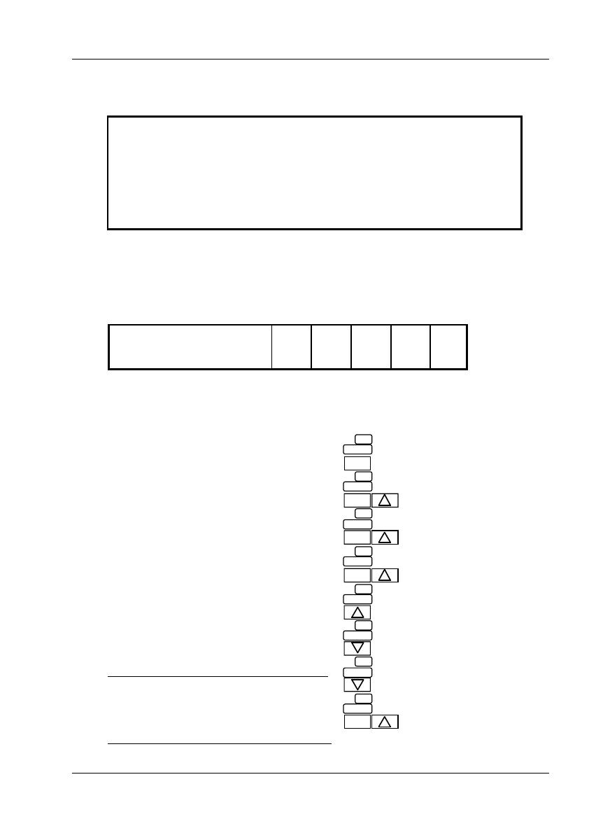
Figure 2.2 Accessing 'AD'
PAR
123.4
L
1
L
2
PAR
L
3
PAR
L
4
PAR
P
0
FS
00
AD
0
PAR
Use the DOWN ARROW to access
first of the list 4 parameters (FS);
Hold PAR, and use the UP ARROW to
enter required address.
Press 'PAR' button.
Display changes to 'L' '1'
Process value display
Hold 'PAR' button and operate
UP ARROW three times.
Display changes to 'L' '2', 'L' '3', 'L' '4'
Release 'PAR' button. Operate UP
ARROW, then enter password.
Use the DOWN ARROW to access
'Address' parameter (AD)
§2.2
Impedance................. 135 to 165 ohms at 3 to 20 MHz
Resistance ................. <110 Ohms/km
Cable capacitance ..... <30 pF/metre
Core diameter ........... 0.34mm2 max. (22 awg)
Cable type ................. Twisted pair, 1x1, 2x2 or 4x1 lines
Signal attenuation ..... 9dB max. over total length of line section
Shielding ................... Cu shielding braid, or shielding braid and shielding foil
Line length/segment (metres) 100 200 400 1000 1200
Max Baud rate (kbit/sec) (kB) 12,000 1,500 500 187.5 93.75
Table 2.1.4 Maximum baud rate versus line length
2.1.3 Cable type
Table 2.1.3 below gives the specification for a suitable cable such as Beldon B3079A.
Table 2.1.3 Cable specification
2.1.4 Maximum Baud rate compared with line length
The maximum transmission speed depends on the length of the cable run including ‘stub’
(distance from the bus to a station) lengths. Guaranteed minimum values are given below.
2.2 Node Address
Each node must be given a unique address, and
this is done in instrument configuration, by ac-
cessing parameter list 4, parameter ‘AD’. Once
the address has been set up, the unit should be
powered off, then on again.
The unit has an address of 254 set at the factory.
This is outside the address range of the PROFI-
BUS protocol (0 to 126), so if the unit is
inadvertantly inserted into the network without
a new address having been set, the bus will not
be affected.
Figure 2.2 shows how to access the parameter
lists, assuming that the user knows the pass-
word. For fuller details of parameter access, see
Chapter three of Part 1 of this manual.
Note: To access the comms. status word
‘CS’ (sections 2.3.1 and 2.4.1) operate the
up arrow key twice from the password
(‘P’‘O’) display.
PROFIBUS
1-8 PROFIBUS User Guide HA260653U501 Issue 1
§2.4
2.3 Adding the unit to the network
Once the unit has been physically wired, and has had an address allocated, a GSD file
must be imported into the network configuration software. A number of GSD files are
provided on the PROFIBUS support disc, along with a software program called
'PROFCONF' which allows the user to edit these GSD files and/or to create new ones.
See Appendix A for details.
The unit can now be added to the network, using the network configuration software, and
I/O data areas can be assigned in the master unit, to represent it.
Once the network is defined, the configuration is written to the master, as described in the
network configuration software documentation, and the network can be started. If all is
well, the communications. status word ‘CS’ in list 4 will be displayed as ‘0003’*. Values
can now be assigned to PROFIBUS outputs and PROFIBUS inputs can be read as re-
quired.
To view CS, use the up arrow key after P0 (ref figure 2.2).
Note:
CS = 0000 means that there is no PROFIBUS card installed or, the card has not
been recognised.
CS = 0002 means that the card is installed but it has not been configured by a
PROFIBUS Master.
2.4 Trouble-shooting
WARNING
Fault finding may affect the network and control system. Ensure that no damage
to personnel or equipment can be caused by any fault finding activity.
2.4.1 No communications
1. Check wiring, verifying the continuity of A and B connections to the master, and en-
sure that the correct terminals have been used. Figure 2.1a above, shows the termina-
tions for this unit.
2. Check the node address, as described in section 2.2 above. Ensure the address is
unique.
3. Verify that a PROFIBUS comms. module is fitted. This can be done by inspecting the
underside of the circuit board for the legend ‘PROFIBUS comms’.
4. Check the communications status word (CS) as described in section 2.2.
CS = 0000 means either that no card is installed, or that it has not been recognised
CS = 0002 means that a PROFIBUS card is installed but it has not been configured by
aPROFIBUS master
CS = 0003 means that a PROFIBUS card has been installed and it has been config-
ured by a PROFIBUS Master.
PROFIBUS
1-9
PROFIBUS User Guide HA260653U501 Issue 1
§2.4.4
2.4.1 No communications (Cont.)
5. Ensure that the network has been correctly configured and that the configuration has
been correctly downloaded to the master.
6. Verify that the GSD file being used is correct, by loading it into the GSD file
configurator to check the format..
7. Ensure that the maximum line length of transmission line has not been exceeded for
the Baud rate in use (Table 2.1.4 above).
8. Ensure that the final node on the transmission line (no matter what type of instrument
it is) is terminated correctly using three resistors as shown in figure 2.1b above, and
that only the first and final nodes are so terminated. Note that some equipment has
built-in pull up and pull down resistors which in some cases can be switched in and
out of circuit. Such resistors must be removed or switched out of circuit for all but the
instruments at each end of the line.
9. Replace any faulty item(s) and re-test.
2.4.2 Intermittent failure to communicate
This fault is shown by the diagnostic status changing, withoutalarms being generated in
the instrument. Section 2.5 below, shows the diagnostics information.
1. Check wiring as in 2.4.1 above. Pay particular attention to the integrity of the screen-
ing and termination
2. Check the number of words in the data exchange against the maximum number the
master can support.
3. Ensure that the maximum line length of transmission line has not been exceeded for
the Baud rate in use (Table 2.1.4 above).
4. Ensure that the final node on the transmission line (no matter what type of instrument
it is) is terminated correctly using three resistors as shown in figure 2.1b above, and
that only the first and final nodes are so terminated. Note that some equipment has
built-in pull up and pull down resistors which in some cases can be switched in and
out of circuit. Such resistors must be removed or switched out of circuit for all but the
instruments at each end of the line.
5. Replace any faulty item(s) and re-test.
2.4.3 Parameter ‘jammed’ at one value and cannot be altered from
the front panel
PROFIBUS DP writes all output data continuously, so that if Output power, Setpoint, or
Auto/Manual status etc. are included in the output data, their settings are stored in the
master data registers will override any setting entered from the front panel. To avoid this
happening, use ‘Demand data’ to write parameter values, ONLY when changes are re-
quired.
2.4.4 Data format or parameter data seems incorrect
Verify that the GSD file is correct for the given application by loading it into the GSD file
configurator program.
PROFIBUS
1-10 PROFIBUS User Guide HA260653U501 Issue 1
2.5 Diagnostic information
PROFIBUS DP provides a message giving diagnostic information for each slave unit.
The process controller uses the ExtDiagData area of this message (bytes 7 and 8) to send a
word containing 16 bits of information relating to the alarm status of the controller as
shown in table 2.5 below. A ‘new diagnostics’ event occurs whenever any of the moni-
tored events changes state.
Bit Description
0 High absolute (loop 1)
1 Low absolute (loop 1)
2 High deviation (loop 1)
3 Low deviation (loop 1)
4 Unacknowledged high absolute (loop 1)
5 Unacknowledged low absolute (loop 1)
6 Unacknowledged high deviation (loop 1)
7 Unacknowledged low deviation (loop 1)
8 High absolute (loop 2)
9 Low absolute (loop 2)
10 High deviation (loop 2)
11 Low deviation (loop 2)
12 Unacknowledged high absolute (loop 2)
13 Unacknowledged low absolute (loop 2)
14 Unacknowledged high deviation (loop 2)
15 Unacknowledged low deviation (loop 2)
Table 2.5 Controller alarm status
2.6 Global commands
Freeze and Sync from a PROFIBUS master have no effect
§2.6
PROFIBUS
1-11
PROFIBUS User Guide HA260653U501 Issue 1
3. OPERATION
PROFIBUS DP performs a cyclical scan of the network devices, during which input and
output data for each node is exchanged.
Values from each node (input data) are read by the controller, which then runs its control
program, and generates a set of values (output data) to be transmitted to the nodes. This
process is called an ‘I/O data exchange’. This process is repeated continuously, to give a
cyclical I/O data exchange.
Examples of input data are
a. A set of digital readings for a digital input
b. The measured temperature and alarm status from a PID controller.
Examples of output data are:
a. A setpoint to be sent to a PID controller
The I/O data exchange can be repeated continuously, can be synchronised at given times,
or can be repeated at a pre-defined interval, which is asynchronous with the controller.
Each node is normally assigned a group of PLC I/O registers, or a single function block,
so that the controlling program can deal with each node’s data as though the node is an in-
ternal device, without having to be concerned about timing problems. This mapping of
node to register or function block is carried out during network configuration, which is
usually carried out using a PC based program.
3.1 I/O data transfer limits.
The PROFIBUS DP standard allows up to 234 bytes of data to be transferred in each di-
rection, during each I/O data exchange. Many PLC masters, however, are unable to sup-
port more than 32 bytes, and this has become a typical value. Input and output data
lengths for a given node are variable, and it is possible to define nodes as read only, write
only or read/write.
The I/O data mixture used by a given slave device is defined by what is called a ‘GSD’
file, which can be edited to change the mapping of node parameters to PROFIBUS inputs
and outputs. This file is imported into the network configuration before the network is
created.
3.2. Data format
Data is transmitted in both directions as a single 16-bit integer value (also called a ‘regis-
ter’). The value is returned as a scaled integer such that 999.9 is returned as 9999, and
1.234 is returned as 1234. The control program in the PROFIBUS master must convert
these integers into floating point numbers if required.
§3.2
PROFIBUS
1-12 PROFIBUS User Guide HA260653U501 Issue 1
4. SPECIFICATION
This information is additional to, or replaces the relevant parts of the specification given in
Part 1 of this manual. For cable specification and Baud rate versus cable length, see sec-
tion 2.1
Safety isolation
Isolation (BS EN61010 dc to 65 Hz) Installation category II, Pollution degree 2†
Any terminal to safety earth: 50V dc or RMS (double isolation)
Vp and C/C’ limitations*
Maximum current source/sink 30mA (5 Volts)
Installation category II:The rated impulse voltage for equipment on nominal 230Volts
is 2500 V.
Pollution category 2: Normally, only non-conductive pollution occurs. Occasion-
ally, however, a temporary conductivity caused by condensation shall be expected.
* Vp and C/C’ may be used ONLY as pull up/down facilities for terminating networks
as shown in section 2.1 above
§4
GSD file configurator
A-1
PROFIBUS User Guide HA260653U501 Issue 1
Appendix A §A1
Appendix A GSD FILES
A1 THE GSD FILE CONFIGURATOR
A1.1 Introduction
The GSD file configuration software (PROFCONF) is supplied on the PROFIBUS sup-
port disc, and provides a simple means of setting up PROFIBUS input and output data
frames. It is a 16-bit Windows application which will run on Windows 3.1, Windows 95
and Windows NT.
A1.2 Installation
Place the PROFIBUS support disc in the disc drive, and run A:\SETUP.EXE from Pro-
gram Manager or Windows Explorer. Follow the on-screen prompts. Several sample
GSD files supplied on the same disc are loaded into the installation directory. These
files are described in section A2 below.
A1.3 Operation
The screen layout is as depicted in figure A1.3 below. Initially, if the mouse cursor is
moved to an area and left there, a hint box appears to explain what that area of screen
does. (Hints can be disabled from the Help menu when they are no longer needed.)
Put simply, the operation of the window is as follows:
1. Select instrument type from the icons at the left edge of the screen.
2. Add device parameters to the PROFIBUS Inputs or PROFIBUS Outputs area.
3. Use Save in order to edit an existing GSD file or Save As to create a new file.
GSD File configurator
A-2 PROFIBUS User Guide HA260653U501 Issue 1
A1.3 OPERATION (Cont.)
A1.3.1 Editing the I/O areas
This can be done in two ways:
a. Display the required parameter in the Device Parameter area, using the Tabs at the
bottom of the area if necessary, then click-and-drag the required parameter to the
PROFIBUS inputs or PROFIBUS Outputs areas as appropriate.
b. Display the required parameter in the Device Parameter area, using the Tabs at the
bottom of the area if necessary, then double-click on the parameter to move it to
whichever of the Inputs or Outputs area is active. (Selected by clicking on the associ-
ated arrow key.
A parameter can be moved within the list, by click-dragging it within the area.
A parameter can be removed from the Inputs/Outputs list by
a. Clicking on the parameter to highlight it, then clicking the Delete key to the right of
the relevant area.
b. Pressing the right mouse button whilst the cursor is over the parameter name. Confir-
mation of the removal is requested by a pop-up box.
The entire list can be removed using the Clear key.
Figure A 1.3 typical GSD File window
Appendix A §A1.3.1
L1 Loop1
Decimal Point Position
Setpoint High Range
Setpoint Low Range
Trim High Range/Limit
Trim Low Range Limit
Setpoint High Limit
Setpoint Low Limit
High Absolute Alarm
Low Absolute Alarm
High Deviation Alarm
Low Deviation Alarm
High Output Limit
Low OutPut Limit
Proportional Band
Device Parameters
L2 Loop2
Use Demand Data
GSD File Customisation Tool (E1.02)
File Help
Profibus Inputs
Delete
Clear
Profibus Outputs
Delete
Clear
Number of Input Words 0
Number of Output Words 0
Description
Cascade/Override
RA M
PAR
SP
Integral Time
Derivative Time
Trim Value
Click on unit
type to be
configured.
Unit icon is
then
highlighted
Tabs
Unit description
entered here
Click here to invoke
'demand data'
Use these arrow keys
to access 'hidden' tabs
Icons mean
(left to right)
Save file
Open file
Save to disc
Print window
Print I/O usage
GSD file configurator
A-3
PROFIBUS User Guide HA260653U501 Issue 1
A1.3.1 EDITING THE I/O AREAS (Cont.)
A maximum of 117 words (input and/or output) including the requirements for demand
data (Appendix B) is imposed by the configurator. When this limit is reached, parameters
must be removed from lists before any further ones can be added. Because many PLCs
cannot support more than 32 words of data at a time, it is recommended that 32 be treated
as the limit.
The View I/O map item in the File menu displays a summary of the I/O memory map for
the current GSD file. This may be pasted to the clipboard for later use, and can be printed
from the File menu.
A1.3.2 Using the file
Before saving the file, it is recommended that a meaningful description in entered in the
area at the bottom of the page. Finally, support for demand data can be enabled by click-
ing in the Use Demand Data box. Demand data is discussed in Appendix B to this
manual.
Once the Input/Output lists are as required, the file should be saved to disc. The file can
now be imported into the PROFIBUS network configuration tool, and used as an applica-
tion program.
Note: Several different GSD files can be created for the same instrument, thus al-
lowing the user to create a library of different applications.
A1.4 Example
This example shows how to set up a GSD file to allow gain scheduling using PID settings
stored in a PLC.
Input data Process variable
Output data Proportional band
Integral time
Derivative time
Cutback high
Cutback low
In such an application, the PLC monitors the Process Variable (e.g. temperature), and
when its value passes into a particular pre-set band, the PLC sets the control parameters
from previously determined settings.
Appendix A §A1.4
GSD File configurator
A-4 PROFIBUS User Guide HA260653U501 Issue 1
EURO6300.GSD (Manual station) L1 (loop 1) parameters
0 Process variable (L1) 1 PV
1 Resolved Setpoint (L1) 5 SP
Word
number
Description
Tag
number
Mne-
monic
Input data
Word
number
Description
Tag
number
Mne-
monic
Input data length (words): 2
Output data length (words): 1
Output data
0 Local Setpoint (L1) 2 SL
EURO630S.GSD (Single loop controller) L1 (loop 1) parameters
0 Decimal Point Pos (L1) 0 DP
1 Process variable (L1) 1 PV
2 Control Output (L1) 3 OP
3 Alarm Status Word (L1) 4 AL
4 Resolved setpoint (L1) 5 SP
5 Resolved Mode (L1) 9 MN
Word
number
Description
Tag
number
Mne-
monic
Input data
0 Local Setpoint (L1) 2 SL
1 Control Output (L1) 3 OP
2 Mode Request (L1) 8 MS
Word
number
Tag
number
Mne-
monic
Output data
Input data length (words): 6
Output data length (words): 3
Appendix A §A2.2
A2 SAMPLE GSD FILES
This section contains input and output data details for the sample GSD files supplied on
the support disc. These files could be used unchanged, but will normally be edited by the
user to suit the application.
The PROFIBUS tag number and mnemonic can be found in tables C3.1 and C3.2 in Ap-
pendix C below.
A2.1 Basic GSD file EURO6300.GSD
A2.2 Single loop controller GSD file: EURO630S.GSD
GSD file configurator
A-5
PROFIBUS User Guide HA260653U501 Issue 1
A2.3 Cascade controller GSD file: EURO630C.GSD
A2.4 Ratio controller GSD file: EURO630R.GSD
EURO630R.GSD (Ratio controller) L1 & 2 (loops 1 & 2) parameters
0 Decimal Point Pos (L1) 0 DP
1 Process variable (L1) 1 PV
2 Control Output (L1) 3 OP
3 Alarm Status Word (L1) 4 AL
4 Resolved setpoint (L1) 5 SP
5 Resolved Mode (L1) 9 MN
6 PV2 Decimal Point (Ratio) 96 DP
7 PV2 Value (Ratio) 97 PV
8 Ratio Decimal Point (Ratio) 104 DP_R
9 Measured ratio (Ratio) 100 MR
Word
number
Description
Tag
number
Mne-
monic
Input data
0 Local Setpoint (L1) 2 SL
1 Control Output (L1) 3 OP
2 Mode Request (L1) 8 MS
3 Ratio setpoint (Ratio) 101 RS
Word
number
Tag
number
Mne-
monic
Output data
Input data length (words): 10
Output data length (words): 4
Appendix A §A2.4
EURO630C.GSD (Cascade/Override controller) L1 & 2 (loops 1 & 2) parameters
0 Decimal Point Pos (L1) 0 DP
1 Process variable (L1) 1 PV
2 Control Output (L1) 3 OP
3 Alarm Status Word (L1) 4 AL
4 Resolved setpoint (L1) 5 SP
5 Resolved Mode (L1) 9 MN
6 Decimal Point Pos (L2) 48 DP
7 Process variable (L2) 49 PV
8 Control Output (L2) 51 OP
9 Alarm Status Word (L2) 52 AL
10 Resolved Mode (L2) 53 SP
Word
number
Description
Tag
number
Mne-
monic
Input data
0 Local Setpoint (L1) 2 SL
1 Control Output (L1) 3 OP
2 Mode Request (L1) 8 MS
3 Local Setpoint (L2) 50 SL
4 Control Output (L2) 51 OP
5 Mode Request (L2) 56 MS
Word
number
Tag
number
Mne-
monic
Output data
Input data length (words): 11
Output data length (words): 6
GSD File configurator
A-6 PROFIBUS User Guide HA260653U501 Issue 1
A2.5 Manual station GSD file: EURO630M.GSD
EURO630M.GSD (Manual station) L1 (loop 1) parameters
0 Decimal Point Pos (L1) 0 DP
1 Process variable (L1) 1 PV
2 Control Output (L1) 3 OP
3 Alarm Status Word (L1) 4 AL
4 Resolved Mode (L1) 9 MN
Word
number
Description
Tag
number
Mne-
monic
Input data
0 Control Output (L1) 3 OP
1 Mode Request (L1) 8 MS
Word
number
Description
Tag
number
Mne-
monic
Output data
Input data length (words): 5
Output data length (words): 2
Appendix A §A2.5
1 / 1

Eurotherm T630 User guide

Type
User guide

Ask a question and I''ll find the answer in the document

Finding information in a document is now easier with AI

Ask the document