Page is loading ...

Muffle Furnace
Model
FP 100/300/310/410
Instruction Manual
- Fourth Edition -
Yamato Scientific Co. LTD.,
This paper has been printed on recycled paper.
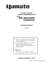
z Thank you for purchasing " Muffle Furnaces, FP
Series" of Yamato Scientific Co., Ltd.
z To use this unit properly, read this "Instruction
Manual" thoroughly before using this unit.
Keep this instruction manual around this unit for
referring at anytime.
WARNING!:
Carefully read and thoroughly understand the
important warning items described in this manual
before using this unit.

Contents
Cautions in Using with Safety................................................................1
• Explanation.................................................................................................................... 1
• Table of Illustrated Symbols .......................................................................................... 2
• Fundamental Matters of “WARNING!” and “CAUTION!” ............................................... 3
Before Using this unit.............................................................................4
• Requirements for Installation......................................................................................... 4
Description and Function of Each Part.................................................7
• Main Unit .......................................................................................................................7
• Control Panel................................................................................................................. 8
Operation Method ...................................................................................9
• Preparation.................................................................................................................... 9
• Selecting operation mode............................................................................................ 12
• Fixed Temperature Operation...................................................................................... 13
• Auto Start Operation.................................................................................................... 15
• Auto Stop Operation.................................................................................................... 18
• Program Operation...................................................................................................... 21
• Operating instructions for program menu.................................................................... 24
• Create New Program................................................................................................... 26
• Edit Program ............................................................................................................... 27
• Delete Program ........................................................................................................... 34
• Function menu............................................................................................................. 35
• Calibration Offset Function.......................................................................................... 45
• Independent overheating prevention device ............................................................... 46
• Temperature Rise/Fall (Reference Data)..................................................................... 47
Handling Precautions ...........................................................................48
Maintenance Method.............................................................................50
•
Daily Inspection and Maintenance .............................................................................. 50
Long storage and disposal...................................................................51
•
When not using this unit for long term / When disposing ............................................ 51
In the Event of Failure….......................................................................52
• Error Display................................................................................................................ 52
• Function of safety devices........................................................................................... 53
• Troubleshooting........................................................................................................... 54
After Service and Warranty ..................................................................55
Specification..........................................................................................56
Wiring Diagram......................................................................................57
Replacement Parts Table......................................................................59
Reference...............................................................................................62
• List of Dangerous Substances .................................................................................... 62

1
Cautions in Using with Safety
Explanation
MEANING OF ILLUSTRATED SYMBOLS
Various symbols are used in this safety manual in order to use the unit without
danger of injury and damage of the unit. A list of problems caused by ignoring
the warnings and improper handling is divided as shown below.Be sure that you
understand the warnings and cautions in this manual before operating the unit.
WARNING!
If the warning is ignored, there is the danger of a problem that
may cause a serious accident or even fatality.
CAUTION!
If the caution is ignored, there is the danger of a problem that may
cause injury/damage to property or the unit itself.
Meaning of Symbols
This symbol indicates items that urge the warning (including the caution).
A detailed warning message is shown adjacent to the symbol.
This symbol indicates items that are strictly prohibited.
A detailed message is shown adjacent to the symbol with specific actions not to
perform.
This symbol indicates items that should be always performed.
A detailed message with instructions is shown adjacent to the symbol.
Illustrated Symbols

2
Cautions in Using with Safety
Table of Illustrated Symbols
Warning
Warning,
generally
Warning,
high voltage
Warning,
high temperature
Warning,
drive train
Warning,
explosive
Caution
Caution,
generally
Caution,
electrical shock
Caution,
scald
Caution,
no road heating
Caution,
not to drench
Caution,
water only
Caution,
deadly poison
Prohibit
Prohibit,
generally
Prohibit,
inflammable
Prohibit,
to disassemble
Prohibit,
to touch
Compulsion
Compulsion,
generally
Compulsion,
connect to the
grounding
terminal
Compulsion,
install on a flat
surface
Compulsion,
disconnect the
power plug
Compulsion,
periodical
inspection

3
Cautions in Using with Safety
Fundamental Matters of “WARNING!” and “CAUTION!”
WARNING!
Do not use this unit in an area where there is flammable or explosive gas
Never use this unit in an area where there is flammable or explosive gas.
This unit is not explosion-proof. An arc may be generated when the power switch is turned on or off,
and fire/explosion may result. (Refer to page62 “List of Dangerous Substances”.)
Always ground this unit
Always ground this unit on the power equipment side in order to avoid electrical shock due to a power
surge.
If a problem occurs
If smoke or strange odor should come out of this unit for some reason, turn off the power key right
away, and then turn off the circuit breaker and the main power. Immediately contact a service
technician for inspection. If this procedure is not followed, fire or electrical shock may result. Never
perform repair work yourself, since it is dangerous and not recommended.
Do not use the power cord if it is bundled or tangled
Do not use the power cord if it is bundled or tangled. If it is used in this manner, it can overheat and
fire may be caused.
Do not process, bend, wring, or stretch the power cord forcibly
Do not process, bend, wring, or stretch the power cord forcibly. Fire or electrical shock may result.
Substances that can not be used
Never use explosive substances, flammable substances and substances that include explosive or
flammable ingredients in this unit. Explosion or fire may occur.
Do not disassemble or modify this unit
Do not disassemble or modify this unit. Fire or electrical shock or failure may be caused.
Do not touch high-temperature parts
The inside of the body or the door may become hot during and after an operation. It may cause burns.
CAUTION!
During a thunder storm
During a thunderstorm, turn off the power key immediately, then turn off the circuit breaker and the main
power. If this procedure is not followed, fire or electrical shock may be caused.

4
Before Using this unit
Requirements for Installation
WARNING!
1. Always ground this unit
• Connect the power plug to a receptacle with grounding connectors.
• Do not forget to ground this unit, to protect you and the unit from electrical shock in case of
power surge. Choose a receptacle with grounding connectors as often as possible.
• Do not connect the grounding wire to a gas pipe, or by means of a lightning rod or telephone
line. A fire or electrical shock will occur.
• Though FP300 model is the 100V single phase model, this model has the large electric
capacity as 26A. Be sure to prepare the power switchboard with the specific grand earth or
specific receptacle.
• FP310/410 model is the 200V single phase mode. Be sure to connect this model to the
specific power switchboard or receptacle for 200V.
2. Choose a proper place for installation
• Do not install this unit in a place where:
♦ Rough or dirty surface.
♦ Flammable gas or corrosive gas is generated.
♦ Ambient temperature exceeds 35°C.
♦ Ambient temperature fluctuates violently.
♦ There is direct sunlight.
♦ There is excessive humidity and dust.
♦ There is a constant vibration.
• Install this unit on a stable place with
the space as shown right. This unit
should be installed horizontally by
using adjusters on the four corners.
More than 30cm
Front side
More than 30cm
(also the reverse side)
More than
1m
52cm

5
Before Using this unit
Requirements for Installation
3. Do not use this unit in an area where there is flammable or explosive gas
• Never use this unit in an area where
there is flammable or explosive gas.
This unit is not explosion-proof. An
arc may be generated when the
power switch is turned ON or OFF,
and fire/explosion may result. (Refer
to page 62 “List of Dangerous
Substances”.)
4. Do not modify
• Modification of this unit is strictly prohibited. This could
cause a failure.
5. Installation on horizontal surface
• Set this unit to the flattest place. Not setting this
unit with its legs contacted to the setting place
surface evenly could cause the vibration or noise,
or cause the unexpectible trouble or malfunction.

6
Before Using this unit
Requirements for Installation
CAUTION!
6. Choose a correct power distribution board or receptacle
• Choose a correct power distribution board or receptacle that meets the unit’s rated electric
capacity.
Electric capacity: FP100: AC100 V, 13A
FP300: AC100 V, 26A
FP310: AC200 V (Single phase), 13A
FP410: AC200V (Single phase), 17.5A
NOTE)
There could be the case that the unit does not run even after turning ON the power. Inspect
whether the voltage of the main power is lowered than the specified value, or whether other
device(s) uses the same power line of this unit. If the phenomena might be found, change the
power line of this unit to the other power line.
Power cord/terminal treatment
Model
Specification for power cord
(Nominal cross-sectional area of conductor)
Terminal treatment
on power source
FP100
3 cores, 2.0 ㎜
2
Attachment plug
FP300
3 cores, 5.5 ㎜
2
FP310
3 cores, 3.5 ㎜
2
FP410
3 cores, 3.5 ㎜
2
Round pressure terminal φ5mm
7. Before/after installing
• It may cause injure to a person if this unit falls down or moves by the earthquake and the
impact. etc.. To prevent, take measures that the unit cannot fall down, and not install to busy
place.
• Touching the unit may cause a burn during and after the operation. To prevent, take measures
that putting up a notice of operating, making an enclosure etc..
8. Handling of power code
• Do not entangle the power cord. This will cause overheating and possibly a fire.
• Do not bend or twist the power cord, or apply excessive tension to it. This may cause a fire
and electrical shock.
• Do not lay the power cord under a desk or chair, and do not allow it to be pinched in order to
prevent it from being damaged and to avoid a fire or electrical shock.
• Keep the power cord away from any heating equipment such as a room heater. The cord's
insulation may melt and cause a fire or electrical shock.
• If the power cord becomes damaged (wiring exposed, breakage, etc.), immediately turn off the
power at the rear of this unit and shut off the main supply power. Then contact your nearest
dealer for replacement of the power cord. Leaving it may cause a fire or electrical shock.
• Connect the power plug to the outlet which is supplied appropriate power and voltage.

7
Description and Function of Each Part
Main Unit
プ
Control panel
Power cord
Power cord (FP100)
Production plate
Mounting area for
exhaust device unit
Earth leakage breaker
Cooling fan
Furnace casing
Door furnace material
Independent overheating
prevention device l
Front view
Rear view

8
Description and Function of Each Part
Control Panel
ERROR
℃ DOOR
STAND BY
1 2 3 4
5
6
7
8
9
10
11
12
13
14
15
16
17
18
POWER
MENU PROGRAM MODE
END
HEATER
FAN
FIXED TEMP
AUTO-START
AUTO-STOP
PROGRAM
① Mode Key
Starts/releases the function menu.
② Program Key
Starts/releases the program menu.
③ Menu Key
Starts/releases the operation menu.
④ Power Key
Turns ON/OFF the power.
⑤ Jog Dial
Selects menu item and edit parameters.
⑥ Main Indicator
Indicates in-furnace temperature and error number.
⑦ Sub Indicator
Indicates various conditions of device with characters.
⑧ ℃ Lamp
Lights on while in-furnace temperature is indicated on the main
indicator.
⑨ Error Lamp
Blinks when any trouble occurs.
⑩ Door Lamp
Lights on while the door is open (not provided on this unit).
⑪ Standby Lamp
Lights on while the device is in standby condition. Blinks while it is
in startup wait state.
⑫ End Lamp
Blinks at autostop or end of the program operation.
⑬ Heater Lamp
Lights on while the heater is active.
⑭ Fan Lamp
Lights on while the fan is active.
⑮ Fixed Temp Lamp
Lights on during the fixed temperature operation. Blinks when
selecting operation mode.
⑯ Auto Start Lamp
Lights on during the auto start operation. Blinks when selecting
operation mode.
⑰ Auto Stop Lamp
Lights on during the auto stop operation. Blinks when selecting
operation mode.
⑱ Program Lamp
Lights on during the program operation. Blinks when selecting
operation mode.

9
Operation Method
Preparation
Connect power plug rightly
The FP series has two specifications; for 100V and 200V depending on the electric capacity used.
Make sure that a proper power terminal/power plug is plugged into an adequate distribution
board/socket depending on the electric capacity. Refer to Page 6, “Choose a correct power
distribution board or receptacle” for the electric capacity.
Set temperature of independent overheating prevention device
Set temperature of independent overheating prevention device. Use the
projections on the right side of respective digits on the dial digital switch to
set the temperature. The device of FP series works in ten times of the set
value. For example, it works at the temperature of 1010℃ if the dial is set to
“101”, and 1110℃ if set to “111”.
• In case there is a small difference between the set values of temperature for independent
overheating prevention device and that of controller, the independent overheating prevention
device may be activated when the temperature reaches to the set value of controller. Set the
temperature of independent overheating prevention device so it be at least 100℃ or more
higher than that of controller.
(When the setting temperature is lower, there is a case that overshoot occurs because this unit
is high temperature type furnace. This independent overheating prevention device should be
used for protect the unit.)
• The default value of the independent overheating prevention device at factory shipment is
1200℃.
Set samples rightly
Do not load too much samples. Leave a certain space in the furnace.
OVERHEAT
PREVENTION
1 0 0

10
Operation Method
Preparation
Turn on earth leakage breaker
Turn on the earth leakage breaker at the right side of device.
ON
The main indicator indicates “- - - -“, and after five seconds the sub indicator indicates the
current date and time, e.g. “2000-09-17 12:01”,the fun rotates and the fan lamp lights on.
2000-09-17 12:01
℃
STAND BY
END
HEATER
FAN
FIXED TEMP
AUTO-START
AUTO-STOP
PROGRAM
NOTE)
The clock on device is not set at the factory shipment. Set the date and time referring to the
instruction shown on Page 42 “Put clock right”.
Press power key
2000-09-17 12:00
FIXED TEMP
AUTO S TART
AUTO STOP
PROGRAM
POWER
MODE PROGRAM
N
U
Pressing the power key turns on the power with pip sound.

11
Operation Method
Preparation
(Continued)
Standing by
2000-09-17 12:01
℃
STANDBY
END
HEATER
FAN
FIXED TEMP
AUTO START
AUTO STOP
PROGRAM.
The main indicator indicates the in-furnace temperature and the ℃ lamp lights on.
The sub indicator displays “standing by” and the standby lamp lights on. This state is
called the “standby state”.
Pressing the power key again turns off the power.
Setting with jog dial
Jog dial is used to select the operation mode or to set temperature and clock.
Turn jog dial
Turning to clockwise: plus
Turning to counterclockwise: minus
Press jog dial
Pressing the jog dial determines the setting and shows the next input window.

12
Operation Method
Selecting operation mode
The following four operation modes are used.
No. Operation mode Function Page
1
Fixed Temperature
Operation
The device controls the constant temperature. 13
2 Auto Start Operation
The device starts operation at the specified time. 15
3 Auto Stop Operation
The device stops operation at the specified time. 18
4 Program Operation
The device starts programmed operation at the specified
time.
21
Operation Selecting Method
NOTE) Make sure that the power is on.
Press the menu key.
MENU
The sub indicator indicates operation mode selection window.
Fixed temp OP.
OP.mode choice
STANDBY
END
HEAT
FAN
FIXED TEMP
AUTO S TART
AUTO S TOP
PROGRAM
The operation mode on the sub indicator blinks and the corresponding lamp blinks. The
indication can be changed in the order of “Fixed temperature operation”→”Auto start”
→”Auto stop”→”program operation” by turning the jog dial to the right. The corresponding
lamp also blinks.
Press the menu key again to cancel the selection.
The operation mode can be selected from the table below.
No. Operation mode Mode Lamp (blink)
Sub Indication
(The hatching area is blinking.)
1
Fixed Temperature
Operation
Fixed Temp Lamp
Fixed temp OP.
OP. mode choice
2 Auto Start Operation Auto Start Lamp
Auto-start OP.
OP. mode choice
3 Auto Stop Operation Auto Stop Lamp
Auto-stop OP.
OP. mode choice
4 Program Operation Program Lamp
Program OP.
OP. mode choice

13
Operation Method
Fixed Temperature Operation
Select operation mode
Press the menu key. Turn the jog dial to indicate “Fixed temp OP.” on the sub indicator and
then press the dial.
Fixed temp OP.
OP. mode choice
℃
FIXED TEMP
AUTO START
AUTO STOP
PROGRAM
Set temperature
The screen displays the window to set temperature after the fixed temperature operation is
determined.
The sub indicator indicates “Setup Temp”. The numerical characters that indicate
temperature blinks. Indicate the desired temperature.
Setup Temp 0℃
Fixed temp OP.
℃
FIXED TEMP
AUTO START
AUTO STOP
PROGRAM
Start operation
Pressing the jog dial determines the set temperature and starts the operation.
Setup Temp1150℃
Fixed temp OP.
℃
FIXED TEMP
AUTO START
AUTO STOP
PROGRAM
The heater lamp lights on and the blinking “Fixed temp” lamp lights on.

14
Operation Method
Fixed Temperature Operation
Observe temperature during operation
The main indicator indicates the in-furnace temperature.
Setup Temp 1150℃↑
2000-09-17 13:25
STANDBY
END
HEATER
FAN
FIXED TEMP
AUTO START
AUTO STOP
PROGRAM
The current state of temperature control is shown with the indications below at the right end
of sub indicator.
↑ : rising
↓ : falling
→ : stable (within ±2.5)
Stop operation
Press the power key to stop the operation.
POWER

15
Operation Method
Auto Start Operation
Select operation mode
Press the menu key. Turn the jog dial to display “Auto-start OP.” on the sub indicator, then
press the dial.
Auto-start OP.
OP.mode choice
℃
FIXED TEMP
AUTO START
AUTO STOP
PROGRAM
Set temperature
The screen displays the window to set temperature after the auto start is determined.
The sub indicator indicates “Setup Temp”. The numerical characters that indicate
temperature blinks. Indicate the desired temperature.
Setup Temp 0℃
Auto-start OP.
℃
FIXED TEMP
AUTO START
AUTO STOP
PROGRAM
Press the jog dial to determine the set temperature.
Setup Temp 1000℃
Auto-start OP.
℃
FIXED TEMP
AUTO START
AUTO STOP
PROGRAM

16
Operation Method
Auto Start Operation
Set time
The screen displays the window to set wait time to operate (period) or start time (the hour)
after the set temperature is determined.
When timer mode is set to ”Time”: wait time can be input.
When timer mode is set to “Clock”: start time can be input.
NOTE) The default setting is “Time”. Refer to Page 37 “Select timer mode”.
Wait time input window
Wait Time 30min
Auto-start OP.
Start time input window
Start Time 13:00
Auto-start OP.
For the input of startup wait time, the indication varies as shown below depending on the
time range to be indicated.
Time Range Indication
0minute to 59minutes
0min to 59min
1hour to 99hours59minutes
1h00m to 99h59m
100hours to 999hours
100hr to 999hr
Turn the jog dial to set the desired time.
Wait Time 0min
Auto-start OP.
℃
FIXED TEMP
AUTO START
AUTO STOP
PROGRAM
Press the jog dial to determine the time set above.
Wait Time 30min
Auto-start OP.
℃
FIXED TEMP
AUTO START
AUTO STOP
PROGRAM

17
Operation Method
Auto Start Operation
After the wait time or start time is determined, the blinking auto start lamp lights on and
the standby lamp blinks instead in startup wait state on auto start mode. The sub indicator
shows the set temperature and remaining time.
Setup Temp 1000℃
start,rear 10min
STANDB Y
END
HEATER
FAN
FIXED TEMP
AUTO START
AUTO STOP
PROGRAM
Start operation
The device starts fixed operation when the remaining time shows “0”. The standby lamp
lights off when the operation is started. The sub indicator shows the same indication as in
the fixed temperature operation.
Setup Temp 1000℃↑
2000-09-17 12:10
STANDBY
END
HEATER
FAN
FIXED TEMP
AUTO S TART
AUTO S TOP
PROGRAM
Stop operation
Press the power key to stop the operation.
POWER

18
Operation Method
Auto Stop Operation
Select operation mode
Press the menu key. Turn the jog dial to indicate the “Auto-stop OP.” on the sub indicator,
then press the dial.
Auto-stop OP.
OP. mode choice
℃
FIXED TEMP
AUTO START
AYTO STOP
PROGRAM
Set temperature
The screen displays the window to set temperature after the auto stop is determined.
The sub indicator indicates “Setup Temp” and the numerical characters that indicate
temperature blinks.
Setup Temp 0℃
Auto-stop OP.
℃
FIXED TEMP
AUTO START
AUTO STOP
PROGRAM
Press the jog dial to determine the set temperature.
Setup Temp 1000℃
Auto-stop OP.
℃
FIXED TEMP
AUTO START
AUTO STOP
PROGRAM
/