Page is loading ...

Operator‘s manual
Translation of the original Operating Manual
Nr.
Tedder
99+2111.EN.80U.0
ALPINHIT 6.6
(Type 2111 :
+ . . 01001)

1900_GB-PAGE 2
Product liability, information obligation
Product liability obliges manufacturers and dealers to issue operating instructions for the machine at the point of sale and to instruct
the customer on the operation, safety and maintenance regulations governing the machine.
Confirmation is required to prove that the machine and the operating instructions have been properly handed over. For this purpose
you have received a confirmation e-mail from Pöttinger. If you have not received this mail, please contact your local dealer. Your
dealer can fill in the handover declaration online.
For the purposes of product liability law, every farmer is an entrepreneur.
In the terms of product liability law, damage to property is any damage arising due to the machine, but not to the machine, and an
excess (500 euros) exists for this liability.
Corporate damage to property within the terms of the product liability law is excluded from this liability.
Be advised!
The operating instructions must also be handed over with any subsequent machine sale or transfer and the transferee
must be instructed in the regulations stated.
Pöttinger - Trust creates Afnity - since 1871
"Quality pays for itself." Therefore we apply the highest quality standards to our products which are constantly monitored by our
in-house quality management and our management board. Because the safety, perfect function, highest quality and absolute
reliability of our machines in operation are the core competencies for which we stand.
There may be deviations between these instructions and the product as we are constantly developing our products. Therefore no
claims may be derived from the data, illustrations and descriptions. Please contact your Specialist Service Centre for any binding
information about specific features of your machine.
We would ask you to please understand that changes to the scope of supply with regard to form, equipment and technical
specifications are possible at any time.
Any form of reprint, translation or reproduction, including excerpts, requires the written approval of Pöttinger Landtechnik GmbH.
All rights according to copyright laws remain expressly reserved by Pöttinger Landtechnik GmbH.
© Pöttinger Landtechnik GmbH – 31st October 2012
Refer to PÖTPRO for additional information about your machine:
Are you looking for suitable accessories for your machine? No problem! All the information you require is here at your disposal.
Scan the QR code on the machine's type plate or look under
www.poettinger.at/poetpro
www.poettinger.at/poetpro
And if we don't have what your looking for, then your Specialist Service Centre is there for you with help and advice.

DE-1901 Dokum D Attachments
- 3 -
PÖTTINGER Landtechnik GmbH
Industriegelände 1
4710 Grieskirchen, Austria
Tel. 07248 / 600 -0
Telefax 07248 / 600-2511
Please place a cross where appropriate.
X
X
According to the product liability please check the above mentioned items.
INSTRUCTIONS FOR PRODUCT HANDOVER
Confirmation is required to prove that the machine and the operating instructions have been properly handed over. For this purpose you have
received a confirmation e-mail from Pöttinger. If you have not received this mail, please contact your local dealer. Your dealer can fill in the hand
-
over declaration online.
Machine checked according to delivery note. All attached parts removed. All safety equipment, drive shaft and operating
devices at hand.
Operation, commissioning and maintenance of the machine or device discussed and explained to the customer on the basis
of the operating instructions.
Check tyres for correct air pressure.
Check wheel nuts for tight t.
Correct PTO shaft speed indicated.
Adaptation to the tractor carried out: Three point adjustment
Cardan shaft correctly cut to length.
Test run carried out and no defects detected.
Function explanation during test run.
Swivel in transport and working position explained.
Information about optional equipment is given.
Indication of unconditional reading of the operating instructions.
EN

- 4 -
1300_GB-INHALT_2111
TABLE OF CONTENTS
EN
Observe
Safety
Hints in the
supplement!
Table of contents
W
ARNIN
WARNINW
G
SI
G
NS
CE mark
.....................................................................
5
Meaning of warning signs
..........................................
5
S
PECIFICATION
Overview
....................................................................
6
Variations
...................................................................
6
T
RACTOR
RE
Q
UIRE
M
ENTS
Tractor
........................................................................
7
Lifting unit (three-point linkage)
.................................
7
Hydraulic connections required
.................................
7
Power connections required
......................................
7
A
TTACHIN
ATTACHINA
G
TO
TRACTOR
Attaching machine to tractor
.....................................
8
Attaching cardan shaft
..............................................
9
Connect hydraulic hoses
..........................................
9
Check functions (trial run)
........................................
10
P
AR
K
IN
G
THE
I
M
P
L
E
M
ENT
Parking the rotary tedder
..........................................
11
Parking in the open
...................................................
11
Winter storage
..........................................................
12
R
OAD
T
RANSPORT
Safety advice
...........................................................
13
Transport runs
..........................................................
13
Repositioning from a working to
..............................
13
a transport position
.................................................
13
Safety advice
............................................................
14
Changing from transport to working position
...........
15
O
PERATION
General working
.......................................................
16
General guidelines on working with the machine
....
17
Guard
........................................................................
17
Tedders
....................................................................
18
Turning
.....................................................................
18
Damping struts
........................................................
18
Working on slopes
...................................................
19
Adjusting the working height
....................................
19
Setting the rotor angle
..............................................
19
Tine adjustment
.......................................................
19
Field edge clearing (boundary tedding) to the left or
right
..........................................................................
20
Jockey wheel
...........................................................
21
Machine release for Aplin tedder
.............................
21
Hydrolift (optional equipment)
..................................
22
Safety advice
...........................................................
23
General maintenance information
............................
23
Cleaning of machine parts
.......................................
23
M
AINTENANCE
Parking in the open
..................................................
23
Winter storage
..........................................................
23
Cardans
...................................................................
23
Hydraulic unit
...........................................................
23
M
AINTENANCE
Maintenance and Servicing
.....................................
24
Input gearbox
..........................................................
24
Tine change
............................................................
24
Lubrication chart
......................................................
25
TECHNICA
L
DATA
Technical Data
.........................................................
27
Optional extras
.........................................................
27
The defined use of the rotary tedder
........................
27
Position of Vehicle Identification Plate
.....................
27
S
UPP
L
E
M
ENT
Lubricants
................................................................
34
Combination of tractor and mounted implement
......
37

- 5 -
1200_GB-WARNBILDZEICHEN_2111
GB
Warning signs
CE mark
The CE mark, which is affixed by the manufacturer, indicates outwardly that this machine conforms
to the engineering guideline regulations and the other relevant EU guidelines.
EU Declaration of Conformity (see Attachment)
By signing the EU Declaration of Conformity, the manufacturer declares that the machine being
brought into service complies with all relevant basic health and safety requirements.
Meaning of warning signs
Information for oc
-
cupational safety
All sections of
these Operating
Instructions con
-
cerning safety are
marked with this
symbol
495.173
Do not enter rotor area while drive motor is running.
Do not touch rotating machine components.
Wait until they have stopped completely.
Shut off engine and remove key before performing
maintenance or repair work.
Do not stand in the implement's swivel range.
Never reach into the crushing danger area as long as
parts may move.
Fit the tines in accordance with the rotor rotation direction.

- 6 -
1700_GB-Uebersicht_2111
GB
s
pecification
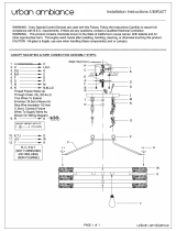
Overview
Descriptions:
(1)
Guard
(2) Warning signs with marker lights (optional equipment)
(3) Feeler wheel (optional)
(4) 3-point headstock with trailing device
(5) Drive
Variations
Description
Hitch type
Description
ALPINHIT 6.6
3-point headstock
Working width: 5.75 m
5
2
1
3
2
4
1
2

- 7 -
2000_DE-Schleppervoraussetzungen_2111
EN
Trac
T
or requiremen
Tor requiremenT
T
s
TsT
Tractor
The following tractor requirements are necessary to operate this machine:
- Tractor output:
from 34KW/45HP to 75kW/100HP
max. 3500 kg tare weight
- Attaching:
Lower link Cat. II
Lifting gear with single-action hydraulics (lifting gear must be switched to
floating position for operation)
- Connections:
see Table "Hydraulic and electrical connections required"
Lifting unit (three-point linkage)
-
The tractor’s lifting unit (three-point linkage) must be
designed for the applicable load. (See technical data)
-
The lifting struts must be set at the same length using
the relevant adjusting equipment
(See the tractor manufacturer’s operating manual)
-
If the lifting struts on the lower links can be fixed in
different positions, then the rear position must be
selected. This relieves the pressure on the tractor’s
hydraulic system.
-
The limiting chains and/or stabilisers for the lower
linkage must be adjusted so that lateral movement of
the hitched implements is not possible. (Safety measure for transportation)
Hydraulic connections required
Design
Consumer
Single-acting hydraulic connection
Standard
Hydraulic lifting
X
Operating pressure
NOTE
Risk of material damage due to incompatible oils.
•
Check the compatibility of the hydraulic oils before connect
-
ing the machine to the hydraulic system of your tractor.
•
Do not mix mineral oils with bio oils!
Minimum operating pressure
170 bar
Maximum operating pressure
200 bar
Power connections required
Design
Consumer
Pin
Volt
Power connection
Standard
Lighting
7-pin
12 V DC
According to DIN-ISO 1724

- 8 -
2000_DE_Anb
A
u
_2111
EN
a
ttaching to tractor
Attaching machine to tractor
DAN
DAN
G
ER
Danger to life due to moving, rolling, tipping or
rotating parts.
Only carry out adjustments when the machine
•
has been parked securely and steadfastly
on level, firm ground.
•
the tractor engine is turned off and the pto
shaft is at a standstill.
•
the tractor's ignition key has been removed.
Danger to life due to parts being thrown off
•
Before every operation, check that the tines
are in good order (free of breakage, cracks
and fracture lines).
•
Before every operation, check the bolt
fittings of the tines.
Danger to life from rotor arms when folding.
•
Do not enter the swivel range of the rotor
arms.
•
Ensure that nobody else enters the danger
area around the rotor arms.
Danger to life through damaged or missing hoop
guards
•
Carry out repairs to hoop guards immedi
-
ately.
NOTE
Risk of material damage due to squeezing hoses,
cables or chains.
•
Make sure to place the hoses, cables and
chains outside the coupling area.
NOTE
Risk of material damage due to tines sticking in the
ground.
•
Do not set the hydraulic unit (ST) to "lower"
if the tedder is fitted to the tractor.
1)
Bring the tractor up to mounting frame and couple the
lower link to the three-point linkage.
2)
Secure the tractor against rolling.
3)
Couple the upper link (1) to the three-point linkage
(standard bracket here)
1
3
3
2
(Bracket with a low-lying upper link here)
1
3
2
4)
Secure the position pins with the linch pin.
Secure
the lower link pins (2) free of play.
5)
Attach the cardan shaft
6)
Centrally fix lower link, free of play, to prevent mower
from swinging out sideways.
7)
Set the length of the upper linkage (9) so that the rotors
slant forward and the spring tines lightly touch the
ground.
8)
Check the setting of the upper linkage (9) frequently
during work.
9)
Lift the tedder to the transport position.

- 9 -
2000_DE_Anb
A
u
_2111
EN
Att
A
AttAAtt
ching to tr
A
ching to trAching to tr
ctor
NOTE
Danger of material damage through the support
feet colliding with the ground or the machine frame.
•
Place the support feet in parking position
before use.
10)
Release the support stand (3), push it upwards, latch
and secure it.
Attaching cardan shaft
WARNIN
WARNIN
G
Risk of injury resulting in death or other serious injury
due to catching and entanglement with a working
cardan shaft where the protective cover is missing
or damaged.
•
Operate the machine only with complete
protective equipment on the cardan shaft.
This includes the cardan shaft protective
rail, the protective shield on the tractor
and the protective cap on the side of the
machine.
•
Always secure the protective cover for the
cardan shaft against rotating by attaching
the safety chains.
•
Attach the safety chains so that there is suf
-
ficient swivelling space for the cardan shaft
in all operating positions.
•
Ensure the safety chains are not able to
become caught in the machine or tractor
components.
•
Have missing or damaged protective covers
repaired immediately and before the next
time the machine is used.
Ensure that only
a specialist workshop carriers out cardan
shaft repairs.
1)
Secure the p.t.o. against accidental starting.
2)
Secure the tractor against rolling.
3)
Clean and grease the p.t.o.
4)
Fold away the cardan shaft holder.
5)
Push the seal on the cardan shaft onto the p.t.o. until
the seal clicks into place.
WARNIN
WARNIN
G
Serious injury through ejected parts of the damaged
cardan shaft.
•
The cardan shaft is to be checked before
first use and adapted if necessary (see
Chapter "Adapting the cardan shaft" in
Attachment B.
6)
Secure the protective cover's holding chains.
Connect hydraulic hoses
WARNIN
WARNIN
G
Risk of an injury resulting in death or other serious
injury due to hydraulic oil leaking at high pressure.
•
Ensure that the hydraulic system on the
tractor and on the machine is depressurised
during maintenance work and when con
-
necting and disconnecting the trailer, both
on the tractor and machine side.
•
The coupled hydraulic hoses must be able
to give slightly with all movements during
cornering without tensioning, kinking or
rubbing, and must not chafe on parts.
•
Seek immediate medical attention for inju
-
ries. There is a risk of infection!
ENVIRON
M
ENT
When working with or on the hydraulics, ensure that fluid
does not escape into the surrounding area.
1)
Secure the p.t.o. against accidental starting.
2)
Secure the tractor against rolling.
3)
Select the appropriate control units.
4)
Place the tractor control unit in the "Neutral" position
(floating position).
5)
Clean the hydraulic plug with a lint-free cloth.
6)
Push the hydraulic plug into the socket on the control
unit until the plug clicks into place.

- 10 -
2000_DE_Anb
A
u
_2111
EN
Att
A
AttAAtt
ching to tr
A
ching to trAching to tr
ctor
Check functions (trial run)
WARNIN
WARNIN
G
Risk of injury resulting in death or other serious
injury from reaching into the turning rotors during
the trial run.
•
Direct everyone out of the danger area
around the tedder prior to the trial run.
•
Start the trial run from the tractor driver’s
seat.
•
Stop the p.t.o. if anything unusual occurs
during the trial run.
Tractor lifting gear:
Check whether the tractor wheels collide with the tedder
with any sharp steering turns (1) in the working and trans
-
port positions.
If this should happen, and there is no suitable coupling
position possible with the included coupling console, then a
special lower linkage console must be fitted. Please contact
your specialist service centre for this.
1
Drive:
Compare the given nominal speed on the tedder with the
tractor's p.t.o. r.p.m. The tedder can be operated with a
540 r.p.m. p.t.o.
Change the tractor p.t.o. direction of rotation to suit the
tedder. (For the tedder's direction of rotation: see the
sticker on the tedder)
Increase the p.t.o. r.p.m. smoothly up to the nominal speed.
Check for unusual noises and vibrations
Check the maximum possible cardan shaft angles in the
transport and working positions. The maximum possible
angle can be obtained from the cardan shaft operating
instructions and must not be exceeded.
TD 37/96/
4
4
TD 37/96/4TD 37/96/
#
L
ighting:
Check whether the electrical cable is connected and the
lighting works.

- 11 -
2000_DE_Abstellen_2111
EN
p
arking the implement
parking the implementp
Parking the rotary tedder
The machine can be parked in either the working position
or transport position.
WARNIN
WARNIN
G
Risk of injury resulting in death or other serious
injury from tilting the parked machine.
•
Park the machine only on solid, level
ground.
•
Protect the machine against rolling away.
•
Lock the support foot with the linch pin.
•
If the ground is soft, enlarge the support
stand area appropriately using suitable
material (e.g. a wooden plank).
-
Pin the bolt on the swing headstock in position B.
A
B
TIP
Only reposition pins when unit is raised.
-
Lower the implement using tractor hydraulic unit and
place it on the supporting leg.
-
Close stopcock (pos. A)
-
Remove the hydraulic lines.
-
Pull down the cardan shaft holder (C)
C
-
Remove the cardan shaft from the tractor and lay it on
the cardan shaft holder.
You must not use the safety chain to suspend the cardan
shaft!
-
Unhitch the implement from the tractor.
Parking in the open
• When
parked
outside
for
longer
periods,
clean
rods
then coat with grease.
FETT
TD
49
/
9
/9
/
3/2
Check when parking
• So
rainwater
can
run
off,
the
holes
"W"
must
not
be
blocked.
W
W
TD7/95/5
TD7/95/5

- 12 -
2000_DE_Abstellen_2111
EN
Parking the machine
Winter storage
-
Thoroughly clean the machine beforehand.
-
Put up weather protection.
-
Protect exposed parts from rust.
-
Lubricate all lubrication points according to plan.
-
Park machine with rotors swivelled up.

- 13 -
1700_Road t
R
anspo
R
t
_2111
EN
r
oad
t
ransport
transportt
Safety advice
W
ARNIN
WARNIN W
G
Danger of injury through machine tipping over.
•
Do not stand in the rotor arm swivel range
during the swivelling procedure.
•
Carry out the folding procedure only on
level, firm ground.
•
Carry out folding procedures in to and out of
the transport position only when machine is
at a standstill.
Danger of injury through being pierced by tines!
•
Do not stand in the rotor arm swivel range
during the swivelling procedure.
Transport runs
Transport runs are defined as journeys from and to the
working location. If such runs include public streets and
lanes, then the machine must be in a roadworthy condition.
The light fittings should be fixed vertically to the road and
must function. If the lighting is dirty then it must be cleaned.
CAUTION
Risk of a slight or moderate injury due to being
pierced by tines.
•
swivel the upper rotor inwards.
Repositioning from a working to
a transport position
DAN
G
ER
Danger to life due to moving, rolling, tipping or
rotating parts.
Only carry out adjustments when the machine
•
has been parked securely and steadfastly
on level, firm ground.
•
the tractor engine is turned off and the pto
shaft is at a standstill.
•
the tractor's ignition key has been removed.
Danger to life from rotor arms when folding.
•
Do not enter the swivel range of the rotor
arms.
•
Ensure that nobody else enters the danger
area around the rotor arms.
1.
The machine must stand with the middle pair of wheels
on the ground.
2.
Operate the control valve (ST) to swivel the exterinal
gyroscopes up to transport position.
a

- 14 -
1700_Road t
R
anspo
R
t
_2111
EN
Road T
R
Road TRRoad T
anspo
RanspoR
RT
3.
Check that the locking hooks (10) are engaged properly.
10
10
TD48/91/3
WARNIN
WARNIN
G
Risk of injury resulting in death or other serious
injury from unexpected movement of the tine arms.
•
Check that the locking hooks on both sides
have engaged properly.
4.
Raise the machine using the tractor lifting device.
5.
Move the linch pin from Position A (=Working position)
to Position B (=Transport position), to lock the swivelling
headstock during transport.
Standard bracket:
B
A
L
Bracket with low-lying upper link:
B
A
L
TIP
Only insert linch pin with machine raised.
6. Lock the swivelling headstock using the bracket.
Safety advice
D
D
AN
G
ER
Danger to life due to moving parts.
•
Do not stand in the rotor arm swivel range
during the swivelling procedure.
•
Ensure that nobody else is in the swivel
range.
Danger to life due to folding during transportation.
If a control unit is touched during transport and the
shut-off valve is not closed, the movement of the
parts can damage the machine.
•
Only transport with the shut-off valve closed.
Danger to life due to piercing tines.
•
Only reverse in the headland or transport
positions!
W
W
ARNIN
WARNIN W
G
Danger of injury through machine tipping over.
•
Do not stand in the rotor arm swivel range
during the swivelling procedure.
•
Carry out the folding procedure only on
level, firm ground.
•
Carry out folding procedures into and out of
the transport position only when machine is
at a standstill.
Danger of injury through being pierced by tines!
•
Do not stand in the rotor arm swivel range
during the swivelling procedure.

- 15 -
1700_Road t
R
anspo
R
t
_2111
EN
Road T
R
Road TRRoad T
anspo
RanspoR
RT
Changing from transport to working
position
-
Make certain that the swivel range is clear and that
no-one is in the danger area.
Changing to a working position (Tedding):
1.
Lower the machine using the tractor's lifting gear, until
the machine's middle pair of wheels stand on the ground.
The outer rotors are still turned upwards.
2.
Release the mechanical locking device:
Set the control valve (ST) to "Raise" and pull on the
cable (S) at the same time.
3.
Set the tractor control valve (ST) to "Lower" The rotors
are lowered into a working position.
4.
Raise the machine using the tractor lifting device.
5.
Insert the pin on the swivelling headstock in Position
A.
TIP
Only insert linch pin with machine raised.
6.
for feeler wheel: Unlock the elongated hole (L) to
establish the floating position.
Standard bracket:
B
A
l
Bracket with low-lying upper link:
A
B
l

- 16 -
2000_Einsatz
_2111
EN
o
peration
General working
WARNIN
WARNIN
G
The machine starting to move or being tipped may lead
to risk of an injury resulting in death or other serious
injury during setting, maintenance or repair work.
•
Park the machine only on solid, level
ground.
•
Bring the device into working Position.
•
Before carrying out setting, maintenance or
repair work to the machine, switch off the
tractor engine and remove the key from the
ignition.
•
Do not work under the machine without it
being supported safely.
WARNIN
WARNIN
G
Risk of injury resulting in death or other serious
injury. when commissioning tractor/trailer units not
safe for traffic or operation.
•
When commissioning the tractor/trailer unit,
check whether the tractor and machine are
in an operationally safe and road-worthy
condition.
•
Move the tractor/trailer unit only when the
tractor and machine are both road-worthy
and operationally safe.
•
Stop using the tractor/trialer unit immediate
-
ly of there are changes to the machine or
its operating behaviour that are relevant to
safety.
WARNIN
WARNIN
G
Risk of injury resulting in death or other serious
injury if entering and standing in the danger area
during work.
•
Ensure that there is no-one within the
machine's rotation and swivel range or in
the danger area between the tractor and the
machine.
•
Only enter the danger areas if the tractor
has been disconnected and
DAN
DAN
G
ER
Danger to life through parts being ejected when the
max. p.t.o speed has been exceeded.
•
Do not exceed max. p.t.o speed of 540
r.p.m.!
DAN
DAN
G
ER
L
ife-threatening danger or material damage through
overloading or incorrectly balancing the tractor.
•
Handling and the steering and braking capa
-
bilities are influenced by attached machines
and ballast weights. When cornering, make
allowances for the implement's wide radius
and inertia, and ensure there is sufficient
steering and braking capability.
•
Always adapt your speed and driving to
the prevailing conditions. Especially when
driving on a slope. Sudden bends must be
avoided when driving parallel to a slope.
There is an increased risk of tipping.
WARNIN
WARNIN
G
Risk of injury resulting in death or other serious injury.
•
Pay attention to the total height of the
machine. Pay particular attention to low or
narrow passages, bridges, power cables
and other obstacles.
•
Observe the legally permitted transport
dimensions.
WARNIN
WARNIN
G
Risk of an injury resulting in death or other serious
injury due to taking people on the machine.
•
Do not take any people with you on the
machine.
WARNIN
WARNIN
G
Risk of injury resulting in death or other serious injury
from losing control of the machine.
•
Never leave the driver's seat when travelling.

- 17 -
2000_Einsatz
_2111
EN
Operati
O
n
General guidelines on working with the
machine
DAN
DAN
G
ER
Risk to life due to clothing, hair or body parts getting
caught by turning rotors.
•
Switch the PTO off before leaving the cabin
•
Ensure that nobody is near the machine
during operation while the rotors are turning.
•
Switch the p.t.o. on immediately as soon as
anyone approaches the danger zone.
495.173
CAUTION
CAUTION
Risk of minor or moderate injury from material being
flung, such as: rocks
•
Ensure that nobody enters the danger area
around the machine.
•
Refer people out of the danger area.
•
Special care is necessary on stony ground,
near houses, roads and paths.
-
Select a driving speed that ensures the entire crop is
picked up cleanly.
-
In the case of an overload, change into a lower gear.
DAN
DAN
G
ER
Danger to life through parts being ejected when the
max. p.t.o speed has been exceeded.
•
Do not exceed max. p.t.o speed of 540
r.p.m.!
p.t.o. speed
-
M
ax. p.t.o. speed = 540 r.p.m.
The most suitable shaft speed is approximately 450
r.p.m.
Pivoting headstock
-
Raise the three-point trailing machine before
entering narrow curves and reversing.
WARNIN
WARNIN
G
Risk of a life-threatening or fatal injury if entering and
standing in the danger area during work.
•
Ensure that there are no people or obsta
-
cles in the pivoting area during work. The
machine swivels automatically to the centre
position (M) and is locked in this position.
•
The lock is released automatically when the
machine is lowered again.
Guard
Before starting work, the guard must be intact. Damaged
guards must be replaced.

- 18 -
2000_Einsatz
_2111
EN
Operati
O
n
Tedders
CAUTION
CAUTION
Risk of minor or moderate injury from material being
flung, such as: rocks
•
Ensure that nobody enters the danger area
around the machine.
•
Refer people out of the danger area.
•
Special care is necessary on stony ground,
near houses, roads and paths.
CAUTION
CAUTION
Risk of minor or moderate injury due to the long-term
noise level of 85dB(A) or more.
•
Use hearing protection when the noise level
in the tractor's cab reaches 85 dB(A) or
above.
-
For tedding, slowly engage the p.t.o. shaft away from
the crop and bring the rotor up to full speed.
-
Smoothly increasing the p.t.o. speed will avoid system-
related noises from the p.t.o. shaft free-running.
-
Adjust the driving speed to suit the terrain and crop.
Turning
-
Raise the implement for turning. The p.t.o. may remain
switched on.
Damping struts
WARNIN
WARNIN
G
Risk of injury resulting in death or other serious injury
from tilting the tractor/trailer unit when driving round
bends on a slope.
•
If the machine is fitted with a three-point
pivoting headstock, model "N", the machine
automatically pivots into the centre position
when lifting with the lifting device. This can
lead to hazardous situations on slopes due
to the machine's inertia (tipping, slipping,
material breakage, etc.)
The damping struts (D) ensure that the swivelling
procedure is not jerky, but slow and continuous.
For working on slopes, we recommend the use of
damping bars (D), as these increase driving safety.
Adjusting the damping value:
How hard or soft the damping struts react can be adjusted
here.
1.
Change the damping setting with the countered screw
(1).
TIP
The behaviour of both damping struts should be as equal
as possible.
1
Setting the strut lengths:
Adjust the strut length so that there is approx. 1 mm clear
-
ance between the heart and the centre bolt on each side
when the combination is fully impacted.
Working instructions:
1.
Jack-knife the combination completely
2.
Check the lateral play of the centre bolt on the inside
of the curve (1). Play should be about 1 mm.
1

- 19 -
2000_Einsatz
_2111
EN
Operati
O
n
3.
Change the lengths of the damping struts:
a.
Straighten the combination
b.
Remove pins from rear end of cylinder rod
c.
Extend cylinder rod
TIP
Reduce the damping value if the piston rod cannot
be pulled out (see "setting the damping value").
Once the length has been changed, reset to the
original damping value.
d.
Adjust the length of the cylinder rod using the
adjusting screw
e.
Refit the cylinder rod
f.
Jack-knife the combination - check the play - repeat
procedure until play is correctly set.
g.
Repeat for the other damping struts
Working on slopes
If the machine is raised using the lifting gear during
cornering, then it automatically swivels to the middle
position. This can lead to hazardous situations on slopes
due to the machine's inertia (tipping, slipping, material
breakage, etc.).
breakage, etc.).
Adjusting the working height
WARNIN
WARNIN
G
Risk of injury resulting in death or other serious
injury from reaching into the tines.
•
Activate the upper link only when the tines
are still.
-
The working height is set by adjusting the upper linkage.
Setting the rotor angle
WARNIN
WARNIN
G
The machine starting to move or being tipped may lead
to risk of an injury resulting in death or other serious
injury during setting, maintenance or repair work.
•
Before carrying out setting, mainenance or
repair work to the machine, switch off the
tractor engine and remove the key from the
ignition.
•
Do not work under the machine without it
being supported safely.
Three different angles can be set via the hole pattern (A).
Much fodder = large angle.
Less fodder = small angle.
Tine adjustment
CAUTION
CAUTION
Risk of a minor or moderate injury due to being parts
being flung.
•
Before every use, check that the tines are in
perfect condition and not broken.
•
Replace any suspect tines immediately.
The tine position can be changed by turning the tine
holder (80).
•
Position "S1"
Standard setting (factory setting)
•
Position "S2"
For difficult conditions e.g. very dense, heavy fodder.
The spreading effect is increased in this tine position.

- 20 -
2000_Einsatz
_2111
EN
Operati
O
n
•
Direction of rotation "R"
Take note when fitting the tines:
TD16/96/1
80
S
1
S
2
80
TD 16/96/2
R
Field edge clearing (boundary tedding)
to the left or right
Field edges can be cleared by swivelling the running wheels.
1.)
Swivelling individual running wheels
-
Press the adjusting lever (7) down
-
Swivel the wheels to the right or left
-
Allow the adjusting lever to re-engage in the required
position.
Note
The tilting axles also allow boundary tedding with three-point
machines. The swivel range (9) is used to the maximum
in this working position.
Therefore the machine must be raised when curving away
from the field edge or at the end of the field.
WARNIN
WARNIN
G
Risk of an injury resulting in death or other serious
injury due to a blow from the raised, pivoting machine.
•
Direct people out of the pivoting area around
the machine before raising it.
NOTE
Risk of material damage from collision of the tractor’s
dual tyres with guard hoop.
•
Check the maximum pivoting angle during
the trial run.
•
In the event of a collision with material dam
-
age, contact your specialist dealer.
/