This product can be included and operated in any Z-Wave network with other Z-Wave
certified devices from other manufacturers and/or other applications. All non-battery
operated nodes within the network will act as repeaters regardless of vendor to increase
reliability of the network.
This product features the latest Security 2 (S2) framework to remove smart home network
hacking risks. This device is equipped with a unique authentication code for trusted
wireless communication.
This is an ETL certified device. ETL, just like UL, is a Nationally Recognized Testing
Laboratory. The ETL mark is proof of product compliance with North American safety
standards.
S2
ADVANCED SETTINGS
Please refer to your controller's user guide for advanced programming
instructions as they are a little different for every soware.
Not sure where to start? Go to www.support.getzooz.com for detailed
instructions on how to change the settings on SmartThings, Vera, and
more. Or just email us: ask@getzooz.com
ASSOCIATION
This device supports Group 1 with up to 1 devices for lifeline communication
and Groups 2 (for Relay 1), 3 (for R2), 4 (for R3) with up to 5 devices each to
send BASIC_SET reports when operated manually.
Z-WAVE CONTROL
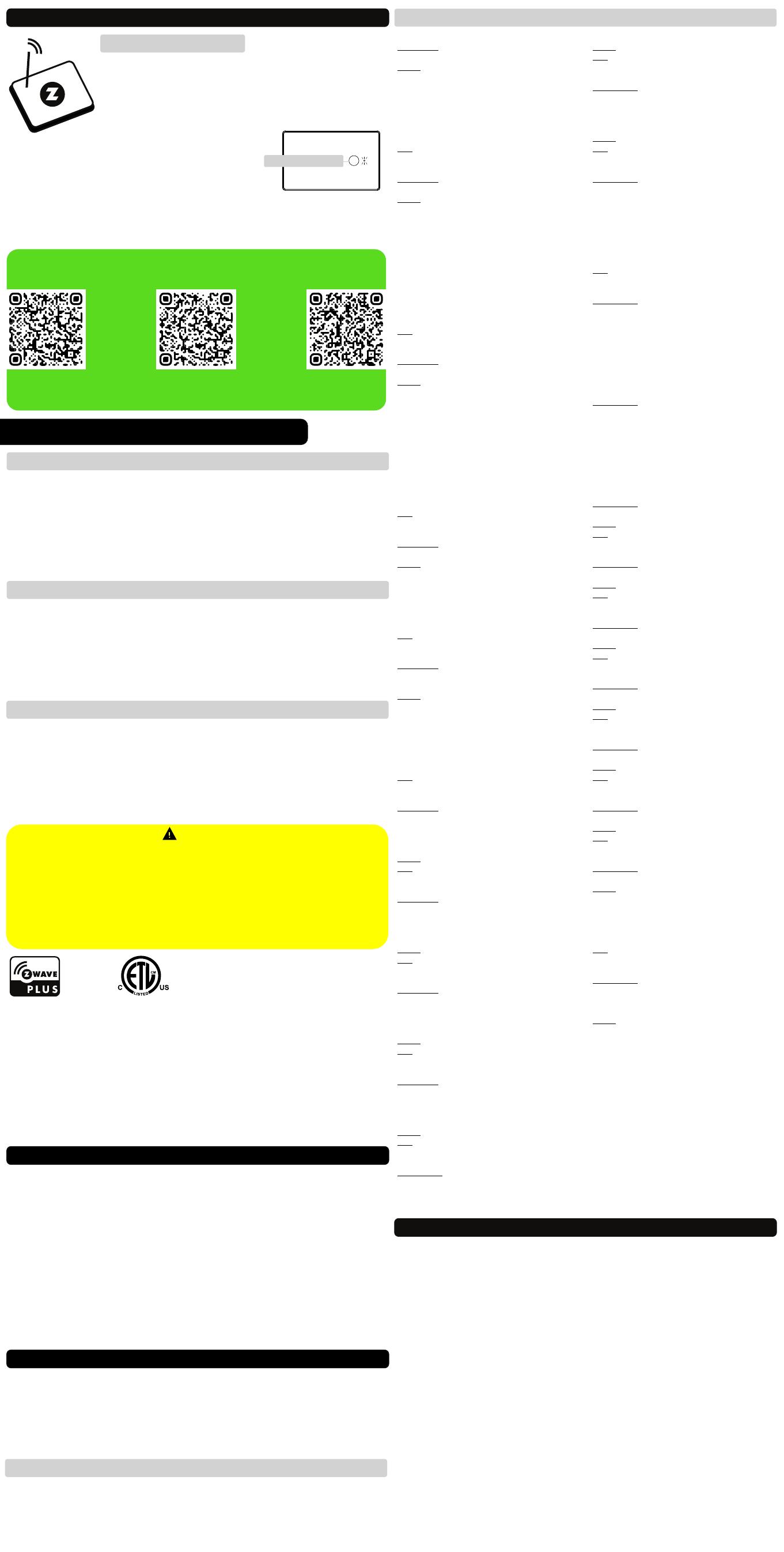
1. ADD DEVICE to your hub
Initiate inclusion (pairing) in the app (or web
interface).
Not sure how? Use the camera on your phone to scan
the QR code below for hub specific instructions.
NEED SOME HELP? ask@getzooz.com
2. Finalize inclusion at the device.
Scan the QR code on the back of the device if
your hub supports SmartStart inclusion.
Click the Z-Wave button 3 times quickly to
1. Bring Z-Wave gateway (hub) and power ityour MultiRelay close to the
2. Put the Z-Wave hub into exclusion mode (not sure how to do that?
ask@getzooz.com)
3. 3 times quicklyClick the Z-Wave button
4. Your hub will confirm exclusion and the MultiRelay will disappear from
your controller's device list
EXCLUSION (REMOVING / UNPAIRING DEVICE)
FACTORY RESET
TROUBLESHOOTING
The MultiRelay won’t add to your system? Try this:
1. Initiate EXCLUSION and click the Z-Wave button 3 times quickly.
2. Click the Z-Wave button 4-5 times quickly when adding it.
3. Bring your MultiRelay closer to the gateway controller (hub), it may be
out of range.
4. Get troubleshooting tips for your hub at www.support.getzooz.com
If your primary controller is missing or inoperable, you may need to reset
the device to factory settings. To complete the reset process manually,
click the Z-Wave button 4 times quickly, the LED indicator will light up,
then quickly click the Z-Wave button 4 times again. The LED indicator
will 3 times to confirm successful reset flash and will then turn off.
NOTE: All previously recorded activity and custom settings will be erased from the device’s memory.
Z-WAVE BUTTON
add the MultiRelay to your network. The LED indicator will blink to
signal communication and remain on for 2 seconds to confirm
inclusion.
CUSTOMIZE YOUR MULTIRELAY
WARRANTY
This product is covered under a 12-month limited warranty or extended 5-year warranty
once registered. To read the full warranty policy or file a warranty claim, please go to
www.getzooz.com/warranty
IN NO EVENT SHALL ZOOZ OR ITS SUBSIDIARIES AND AFFILIATES
BE LIABLE FOR ANY INDIRECT, INCIDENTAL, PUNITIVE, SPECIAL, OR
CONSEQUENTIAL DAMAGES, OR DAMAGES FOR LOSS OF PROFITS,
REVENUE, OR USE INCURRED BY CUSTOMER OR ANY THIRD PARTY,
WHE-THER IN AN ACTION IN CONTRACT, OR OTHERWISE EVEN IF
ADVISED OF THE POSSIBILITY OF SUCH DA-MAGES. ZOOZ'S
LIABILITY AND CUSTOMER'S EXCLUSIVE REMEDY FOR ANY CAUSE
OF ACTION ARISING IN CON-NECTION WITH THIS AGREEMENT OR
THE SALE OR USE OF THE PRODUCTS, WHETHER BASED ON
NEGLIGENCE, STRICT LIABILITY, BREACH OF WARRANTY, BREACH
OF AGREEMENT, OR EQUITABLE PRINCIPLES, IS EXPRESSLY
LIMITED TO, AT ZOOZ'S OPTION, REPLACEMENT OF, OR
REPAYMENT OF THE PURCHASE PRICE FOR THAT POR-TION OF
PRODUCTS WITH RESPECT TO WHICH DA-MAGES ARE CLAIMED.
ALL CLAIMS OF ANY KIND ARISING IN CONNECTION WITH THIS
AGREEMENT OR THE SALE OR USE OF PRODUCTS SHALL BE
DEEMED WAIVED UNLESS MADE IN WRITING WITHIN THIRTY (30)
DAYS FROM ZOOZ'S DELIVERY, OR THE DATE FIXED FOR DELI-VERY
IN THE EVENT OF NONDELIVERY.
FCC NOTE
THE MANUFACTURER IS NOT RESPONSIBLE FOR ANY RADIO OR TV
INTERFERENCE CAUSED BY UNAUTHORIZED MODIFICATIONS TO
THIS EQUIPMENT. SUCH MODIFICATIONS COULD VOID THE USER’S
AUTHORITY TO OPERATE THE EQUIPMENT. STORE INDOORS WHEN
NOT IN USE. SUITABLE FOR DRY LOCATIONS ONLY. DO NOT
IMMERSE IN WATER. NOT FOR USE WHERE DIRECTLY EXPOSED TO
WATER.
This device complies with Part 15 of the FCC Rules.
Operation is subject to the following conditions:
1. This device may not cause harmful interference,
2. This device must accept any interference received, including
interference that may cause undesired operation.
Any Changes or modifications not expressly approved by the party
responsible for compliance could void the user's authority to
operate the equipment.
This equipment has been tested and found to comply with the
limits for a Class B digital device, pursuant to part 15 of the FCC
Rules.
These limits are designed to provide reasonable protection against
harmful interference in a residential installation.
This equipment generates, uses and can radiate radio frequency
energy and, if not installed and used according to instructions,
may cause harmful interference to radio communications.
However, there is no guarantee that interference will not occur in
any given installation.
If this equipment causes harmful interference to radio or television
reception, the user may try to correct the interference by taking
one or more of the following measures:
- Reorient or relocate receiving antenna
- Increase the separation between equipment and receiver
- Connect equipment into a separate outlet or circuit from receiver
- Consult the dealer or an experienced radio/TV technician for
additional assistance
All brand names displayed are trademarks of their respective
holders.
© Zooz 2022
On Off Status Aer Power Failure
Parameter 1: Set the on off status for the relays aer
power failure.
Values: 0 – ALL relays forced to OFF (regardless of state
prior to power outage); 1 – ALL relays remember and
restore on/off status aer power failure (default); 2 – ALL
relays forced to ON (regardless of state prior to power
outage); 3 – Relay 1 and Relay 2 remember and restore
on/off status aer power failure, Relay 3 forced to OFF; 4
– Relay 1 and Relay 2 remember and restore on/off
status aer power failure, Relay 3 forced to ON.
Size: 1 byte dec.
Switch Type for Relay 1 (Sw1)
Parameter 2: Choose the wall switch type you want to
connect to the Sw1 terminal. Default: 2.
Values: 0 – for lights only 1 – momentary ; toggle switch
(light on when the switch is toggled up, light off when
the switch is toggled down); 2 toggle switch (state –
changes whenever the switch is toggled); 3 – garage
door momentary mode for Z-Wave control 4 – leak ( );
alarm (water sensor); 5 – heat alarm; 6 – motion alert; 7
– open/close alert (door sensor); 8 – CO alarm; 9 – CO2
alarm; 10 – on/off report (dry contact switch/sensor); 11
– garage door mode for the relay (momentary contact)
and door sensor type for the input (use with wired
analog door/window sensors and garage gate openers).
Press and hold the Z-Wave button for 5 seconds to
change mode manually between values 0 and 3.
Size: 1 byte dec.
Switch Type for Relay 2 (Sw2)
Parameter 3: Choose the wall switch type you want to
connect to the Sw2 terminal. Default: 2.
Values: 0 – for lights only 1 – momentary ; toggle switch
(light on when the switch is toggled up, light off when
the switch is toggled down); 2 toggle switch (state –
changes whenever the switch is toggled); 3 – garage
door momentary mode for Z-Wave control ; 4 – leak ( )
alarm (water sensor); 5 – heat alarm; 6 – motion alert; 7
– open/close alert (door sensor); 8 – CO alarm; 9 – CO2
alarm; 10 – on/off report (dry contact switch/sensor); 11
– garage door mode for the relay (momentary contact)
and door sensor type for the input (use with wired
analog door/window sensors and garage gate openers).
Click-click’n’hold the Z-Wave button for 5 seconds to
change mode manually between values 0 and 3.
Size: 1 byte dec.
Switch Type for Relay 3 (Sw3)
Parameter 4: Choose the wall switch type you want to
connect to the Sw3 terminal.
Values: 0 – for lights only 1 – momentary ; toggle switch
(light on when the switch is toggled up, light off when
the switch is toggled down); 2 toggle switch (state –
changes whenever the switch is toggled); 3 – garage
door momentary mode for Z-Wave control . D : 2. ( ) efault
Click-click-click’n’hold the Z-Wave button for 5
seconds to change mode manually for values 0-3.
Size: 1 byte dec.
LED Indicator Control
Parameter 5: Choose if you want the LED indicator to
turn on when any of the relays are on or if all of them are
off, or if you want it to remain on or off at all times.
Values: 0 – LED indicator is on when ALL of the relays are
off, LED indicator is off when any of the relays is on
(default); 1 – LED indicator is on when any of the relays is
on, LED indicator is off when ALL of the relays are off; 2 –
LED indicator is always OFF; 3 – LED indicator is always
ON.
Click the Z-Wave button 5 times quickly to change
mode manually.
Size: 1 byte dec.
Auto Turn-Off Timer for Relay 1
Parameter 6: Use this parameter to set the time aer
which you want the device connected to Relay 1 to
automatically turn off once it has been turned on. The
number entered as value corresponds to the number of
minutes, seconds, or hours (set the unit in Par. 15).
Values: 0 – timer disabled (default); 1 – 65535.
Size: 4 byte dec.
Auto Turn-On Timer for Relay 1
Parameter 7: Use this parameter to set the time aer
which you want the device connected to Relay 1 to
automatically turn on once it has been turned off. The
number entered as value corresponds to the number of
minutes, seconds, or hours (set the unit in Par. 16).
Values: 0 – timer disabled (default); 1 – 65535.
Size: 4 byte dec.
Auto Turn-Off Timer for Relay 2
Parameter 8: Use this parameter to set the time aer
which you want the device connected to Relay 2 to
automatically turn off once it has been turned on. The
number entered as value corresponds to the number of
minutes, seconds, or hours (set the unit in Par. 17).
Values: 0 – timer disabled (default); 1 – 65535.
Size: 4 byte dec.
Auto Turn-On Timer for Relay 2
Parameter 9: Use this parameter to set the time aer
which you want the device connected to Relay 2 to
automatically turn on once it has been turned off. The
number entered as value corresponds to the number of
minutes, seconds, or hours (set the unit in Par. 18).
Values: 0 – timer disabled (default); 1 – 65535.
Size: 4 byte dec.
Auto Turn-Off Timer for Relay 3
Parameter 10: Use this parameter to set the time aer
which you want the device connected to Relay 3 to
automatically turn off once it has been turned on. The
number entered as value corresponds to the number of
minutes, seconds, or hours (set the unit in Par. 19).
Values: 0 – timer disabled (default); 1 – 65535.
Size: 4 byte dec.
Auto Turn-On Timer for Relay 3
Parameter 11: Use this parameter to set the time aer
which you want the device connected to Relay 3 to
automatically turn on once it has been turned off. The
number entered as value corresponds to the number of
minutes, seconds, or hours (set the unit in Par. 20).
Values: 0 – timer disabled (default); 1 – 65535.
Size: 4 byte dec.
Enable/Disable Manual Control for Sw1
Parameter 12: Enable or disable physical on/off control
of Relay 1 from the wall switch connected to Sw1
terminal. If disabled, you’ll only be able to control the
connected device via Z-Wave.
Values: 0 – local control disabled. 1 – local control
enabled 2 – local control disabled with (default).
enabled on/off reports (connected switch won’t control
the relay but it will send on/off reports to the hub when
triggered).
Size: 1 byte dec.
Enable/Disable Manual Control for Sw2
Parameter 13: Enable or disable physical on/off control
of Relay 2 from the wall switch connected to Sw2
terminal. If disabled, you’ll only be able to control the
connected device via Z-Wave.
Values: 0 – local control disabled. 1 – local control
enabled 2 – local control disabled with (default).
enabled on/off reports.
Size: 1 byte dec.
Enable/Disable Manual Control for Sw3
Parameter 14: Enable or disable physical on/off control
of Relay 3 from the wall switch connected to Sw3
terminal. If disabled, you’ll only be able to control the
connected device via Z-Wave.
Values: 0 – local control disabled. 1 – local control
enabled 2 – local control disabled with (default).
enabled on/off reports.
Size: 1 byte dec.
Auto Turn-Off Timer Unit for Relay 1
Parameter 15: Choose between seconds, minutes, and
hours as the unit for the auto turn-off timer for Relay 1.
Values: 0 – minutes (default); 1 – seconds; 2 – hours.
Size: 1 byte dec.
Auto Turn-On Timer Unit for Relay 1
Parameter 16: Choose between seconds, minutes, and
hours as the unit for the auto turn-on timer for Relay 1.
Values: 0 – minutes (default); 1 – seconds; 2 – hours.
Size: 1 byte dec.
Auto Turn-Off Timer Unit for Relay 2
Parameter 17: Choose between seconds, minutes, and
hours as the unit for the auto turn-off timer for Relay 2.
Values: 0 – minutes (default); 1 – seconds; 2 – hours.
Size: 1 byte dec.
Auto Turn-On Timer Unit for Relay 2
Parameter 18: Choose between seconds, minutes, and
hours as the unit for the auto turn-on timer for Relay 2.
Values: 0 – minutes (default); 1 – seconds; 2 – hours.
Size: 1 byte dec.
Auto Turn-Off Timer Unit for Relay 3
Parameter 19: Choose between seconds, minutes, and
hours as the unit for the auto turn-off timer for Relay 3.
Values: 0 – minutes (default); 1 – seconds; 2 – hours.
Size: 1 byte dec.
Auto Turn-On Timer Unit for Relay 3
Parameter 20: Choose between seconds, minutes, and
hours as the unit for the auto turn-on timer for Relay 3.
Values: 0 – minutes (default); 1 – seconds; 2 – hours.
Size: 1 byte dec.
DC Motor Mode
Parameter 24: Sync R1 and R2 together to prevent them
from being activated at the same time.
Values: 0 – DC motor mode disabled (relays will activate
whenever they're triggered); 1 – DC motor mode
enabled (relay will check the status of the other relay
aer being triggered and will shut the other relay off
before activating so that only one of the relays is on at
the same time). Default: 0.
Size: 1 byte dec.
Reversed Reports for Sw1
Parameter 28: Reverse the reported values for your
selected input type on Sw1 terminals (select the same
value as you chose for parameter 2 to reverse the values
for open and closed circuit).
Values: 0 – values reported as normally open, not
reversed (default); 4 – leak alarm (water sensor); 5 – heat
alarm; 6 – motion alert; 7 – open/close alert (door
sensor); 8 – CO alarm; 9 – CO2 alarm; 10 – on/off report
(dry contact switch/sensor).
Size: 1 byte dec.
NOTE: This will not affect the relay behavior if you leave
the input linked to the output, it will still trigger the relay
to on when the circuit is closed (if connected to R1),
regardless of the reported value. This setting only affects
the reports displayed in the hub for the input and does
not affect the relay (output) behavior.
Use parameters 29 and 30 to reverse reporting on
Sw2 and Sw3 inputs respectively.
QUESTIONS?
ask@getzooz.com | www.support.getzooz.com
ŸThis product should be installed indoors upon completion of any building renovations.
ŸPrior to installation, the device should be stored in a dry, dust-and-mold-proof place.
ŸDo not install the device in a place with direct sun exposure, high temperature, or humidity.
ŸKeep away from chemicals, water, and dust.
ŸEnsure the device is never close to any heat source or open flame to prevent fire.
ŸEnsure the device is connected to an electric power source that does not exceed the
maximum load power.
ŸNo part of the device may be replaced or repaired by the user.
WARNING
COMMAND CLASSES
This device requires the following command classes to be supported and
recognized by your Z-Wave controller:
COMMAND_CLASS_ZWAVEPLUS_INFO
COMMAND_CLASS_SWITCH_BINARY
COMMAND_CLASS_ASSOCIATION
COMMAND_CLASS_MULTI_CHANNEL_ASSOCIATION
COMMAND_CLASS_ASSOCIATION_GRP_INFO
COMMAND_CLASS_TRANSPORT_SERVICE
COMMAND_CLASS_VERSION
COMMAND_CLASS_MANUFACTURER_SPECIFIC
COMMAND_CLASS_DEVICE_RESET_LOCALLY
COMMAND_CLASS_POWERLEVEL
COMMAND_CLASS_CONFIGURATION
COMMAND_CLASS_MULTI_CHANNEL
COMMAND_CLASS_SECURITY_2
COMMAND_CLASS_SUPERVISION,
COMMAND_CLASS_FIRMWARE_UPDATE_MD_V2
PAGE 4PAGE 3
3 x CLICK
SmartThings Hubitat Vera
Choose your hub and scan the QR code with your phone’s camera.
Then click on the link to access step-by-step pairing instructions.
Get more tutorials and helpful tips at www.support.getzooz.com


